Table of Contents
Advertisement
Quick Links
Installation Instructions
Pressure Transmitter Unit PTU 025
®
VLT
HVAC Drive FC 102
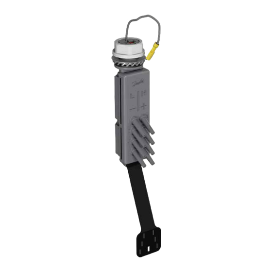
Items Supplied
See Illustration 1.1 for the list of supplied items.
1
M25 nut
2
M25 ground washer connection
3
M25 star washer
4
M25 gasket
Table 1.1
Illustration 1.1 Pressure Transmitter Unit PTU 025 and Items Supplied
5
Pressure Transmitter Unit PTU 025
6
Tube relief plate
7
Interface cable for the C-option port
8
Cable binders
Danfoss A/S © 12/2017 All rights reserved.
MI08A102
Advertisement
Table of Contents

Related Manuals for Danfoss PTU 025


Summary of Contents for Danfoss PTU 025
-
Page 1: Installation Instructions
M25 ground washer connection Tube relief plate M25 star washer Interface cable for the C-option port M25 gasket Cable binders Table 1.1 Illustration 1.1 Pressure Transmitter Unit PTU 025 and Items Supplied Danfoss A/S © 12/2017 All rights reserved. MI08A102... -
Page 2: Safety Instructions
® HVAC Drive FC 102 NOTICE To order the unit, use the following ordering number: The PTU 025 unit can be installed in IP55 and IP66 Model Ordering number enclosures, and can be connected with the frequency PTU 025, 4 inputs 134B5925 converter using the C-option interface. -
Page 3: Mechanical Installation
Pressure Transmitter Unit PTU 025 Installation Instructions ® HVAC Drive FC 102 Mechanical installation Prepare the hole for the installation The options to mount the PTU 025 unit on an IP55/66 enclosure include the following: • Factory-installed M25 tread. • Using the knock-out plate. -
Page 4: Electrical Installation
Mount the front cover of the frequency converter. Power up the frequency converter. Ensure that the frequency converter identifies the PTU 025 unit. Illustration 1.5 PTU 025 Electrical Connection to the C-option Port Danfoss A/S © 12/2017 All rights reserved. MI08A102... - Page 5 Perform the configuration in parameter group 5-** Main Menu - Digital In/Out and parameter group 6-** Main Menu - Analog In/Out. See the wiring diagram in Illustration 1.6. Illustration 1.6 Wiring Diagram MI08A102 Danfoss A/S © 12/2017 All rights reserved.
- Page 6 Mounting the Pressure Tubes PTU 025 has 5 mm (0.2 in) tube connection taps. Attach high-pressure input tubes to the taps labeled H +, and the low-pressure tubes on the L - taps. To prevent clogging of sensors, attach tubes to all connection taps. See Illustration 1.7.
-
Page 7: Parameter Configuration
For options [1] Linear and [2] Square root, the pressure threshold at 0 speed equals 10% of the value entered in Use the LCP or MCT 10 Set-up Software to configure PTU 025. parameter 31-21 Below level threshold or parameter 31-22 Above The PTU 025 option can be configured for the following level threshold.See Illustration 1.9. - Page 8 Illustration 1.9. Illustration 1.9 Pressure Sensor Data on the LCP 31-26 Pressure Sensor 1 Range: Function: 0 Pa [-500 - 500 Pa] Shows the readout of pressure sensor 1. Danfoss A/S © 12/2017 All rights reserved. MI08A102...
-
Page 9: Application Integration
Application Integration PTU 025 is designed for central air handling units with 1 or more filters in the inlet/outlet part and with fan control based on the airflow or pressure level in the ventilation system. Separate frequency converters with separate pressure transmitter units control the inlet and outlet. -
Page 10: Dimensional Drawings
Illustration 1.11 Dimensional Drawings Danfoss can accept no responsibility for possible errors in catalogues, brochures and other printed material. Danfoss reserves the right to alter its products without notice. This also applies to products already on order provided that such alterations can be made without subsequential changes being necessary in specifications already agreed. All trademarks in this material are property of the respective companies. Danfoss and the Danfoss logotype are trademarks of Danfoss A/S.