Table of Contents
Advertisement
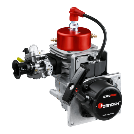
OWNER'S MANUAL
Model: G320PUM
Model code: 967289101
• This engine is designed for radio controlled boat use.
• When replacing parts, use only parts which have been certified by
Zenoah.
• Zenoah assumes that no responsibility for this engine that is modified
or used for any other applications.
• Purchaser has all responsibilities against any laws and regulations
existing in the country, Zenoah is exempt from such laws and
regulations.
• Read and completely understand this OWNER'S MANUAL before
operating this engine.
for radio control Boat
WARNING
115767226 (508)
Advertisement
Table of Contents

Related Manuals for Zenoah G320PUM


Summary of Contents for Zenoah G320PUM
- Page 1 • When replacing parts, use only parts which have been certified by Zenoah. • Zenoah assumes that no responsibility for this engine that is modified or used for any other applications. • Purchaser has all responsibilities against any laws and regulations existing in the country, Zenoah is exempt from such laws and regulations.
-
Page 3: Table Of Contents
Contents Safety Precautions ............4 Engine Assembling............5 Engine Mounting............6 Screw Propeller and Exhaust System .......7 Fueling System............8 Starting ..............9 How to Stop The Engine..........9 Carburetor Adjustment ..........10 Engine Break-In............12 Operation..............12 Maintenance ............13 Special Tools ............18 Service Guide ............19 Trouble Shooting .............22 Parts List..............24 Warranty ..............27... -
Page 4: Safety Precautions
Safety Precautions • This manual describes the engine. For its mounting and control, see the instruction manual provided by model boat manufacturer. • This engine is designed for model boat use. If it is used for any other purpose, we cannot be responsible for its reliability, safety and any laws/regulations in the country. -
Page 5: Engine Assembling
3. Gasket (T2075-14120) 4. Carburetor SET (585879701) 5. Air-funnel (848ES08300) 6. Spacer (1142-83110) 7. Bolt (8488455000) G320PUM CAUTION Make sure that gasket and carburetor are mounted as described in fig.1. The engine does not start if carburetor is mounted upside down position. -
Page 6: Engine Mounting
Engine Mounting Make sure that the engine is to be mounted according to the instruction manual provided by model boat manufacturer. In case such instruction manual is not available, make sure that the engine should be mounted at least by 4 points both at engine's PTO side and recoil starter side. [ Note ] 1) Be sure to set flat washers or metal plates on the reverse side of the mount to prevent bolts from sinking into the mount. -
Page 7: Screw Propeller And Exhaust System
Screw-Propeller and Exhaust System The exhaust system (e.g., muffler) is not equipped with this engine as standard. When you select the exhaust system, check the engine speed (rpm) when the maximum output is generated by using the exhaust system you are going to select. And then decide the appropriate screw-propeller that would meet such engine speed (rpm) that the exhaust system requires. -
Page 8: Fueling System
Fueling System • Mix gasoline (octane over 95) and high grade 2 cycle engine oil (mixing use type; JASO FC grade or ISO-L-EGC grade) at mixing ratio 25:1. • The mixing ratio is according to the oil recommendation. [ NOTE ] 1) Gasoline may contain maximum of 10% Ethanol (grain alcohol) or up to 15% MTBE (Methyl tertiary-butyl ether). -
Page 9: Starting
Starting ● How to start a. Fill the fuel tank with the fuel. b. Push the priming bulb upper the carburetor until fuel appears in the priming bulb. c. Choke the engine and open the throttle valve approximately 1/4~1/3 of the full open position. -
Page 10: Carburetor Adjustment
Carburetor Adjustment The carburetor is provided with 3 adjust screws they may need a little adjustment depending on the temperature, atmospheric pressure (altitude), and an exhaust system, etc. of the area where the engine is used. Start the engine without making any adjustments. - Page 11 Carburetor Adjustment Idle Screw: Turning this screw clockwise increases the idling R.P.M. Turning it counterclockwise decreases the idling R.P.M Low Speed needle: This is the fuel adjust screw (not the air screw). Turning this needle clockwise makes the mixture gas leaner and turning it counterclockwise makes it richer. Set this needle at a position which is 1/4 open from best mixture (maximum R.P.M.) position.
-
Page 12: Engine Break-In
Engine Break-In No specific break-in is required. The engine is gradually broken-in as it is used and the output is also gradually increased. For checking the whole conditions of the boat, it may be better to operate the engine at slow RPM for 1/3 tank and mid-high RPM for 2/3 tank. Operation •... -
Page 13: Maintenance
Maintenance 1) MAINTENANCE CHART Before Every Every Items Action 25 hours 100 hours Note Leakage, ✔ ✔ ✔ Check Damage/Crack ✔ ✔ ✔ Idling Speed Check/Adjust ✔ ✔ Spark Plug(gap) Check/Adjust Replace if necessary ✔ ✔ ↑ Cylinder(barrel) Check/Cleaning ✔ ✔... - Page 14 Maintenance 2) SPECIFICATIONS AND TECHNICAL DATA Items Unit G320PUM Remarks Bore x Stroke 38 x 28 Displacement 31.8 Effective Compression Ratio Type Walbro WT Carburetor Venture(mm) ø13.5 Starting Recoil Starter Type Ignition Timing BTDC 30°/7000rpm Standard CMR7H Spark Plug ↑...
- Page 15 Maintenance 3) MAINTENANCE SPECIFICATIONS G320PUM Items Standard Limit Measuring Device Remarks Bore (mm) ø38 Plating damaged Eye Checking Cylinder At the skirt end and Diameter (mm) ø37.97 ø37.87 Micro Meter the right angle to the piston pin. Piston Ring 1.01 1.11...
- Page 16 Maintenance 4) CARBURETOR Items Standard Limit Measuring Device Remarks Metering Lever set (mm) 1.65 ± 0.16 Vanier Inlet Valve Opening Pressure (kg/cm 1.3~2.3 Leak Tester Inlet Valve Closing Pressure (kg/cm 0.7~1.7 Leak Tester 5) IGNITION SYSTEM Items Standard Limit Measuring Device Remarks Spark Plug Air Gap (mm) 0.6~0.7...
- Page 17 Maintenance 6) TIGHTENING TORQUE Items Screw Size Standard (N·m) Limit (N·m) Remarks Carburetor M5 (P=0.8) 2.9~3.9 Apply Three Bond TB1342H Insulator M5 (P=0.8) 3.9~4.9 (Low Strength) or Equivalent Pully Assy M8 (P=1.0) 12.7 9.8~14.7 Cylinder M5 (P=0.8) 6.9~8.8 Crankcase M5 (P=0.8) 4.7~6.9 Spark Plug M10 (P=1.0)
-
Page 18: Special Tools
Special Tools Part Name Part No. External Appearance Usage Puller Assy 577409701 To remove rotor. To hold crankshaft when disassembling/assembling Piston Stopper 4810-96220 the rotor. For socket screw of Hex Wrench 3304-97611 4mm, 5mm and 6mm. Snap Ring Pliers 5500-96110 To remove snap ring. -
Page 19: Service Guide
Service Guide Fig.2 1. REMOVING ROTOR Piston Stopper 1) Remove the spark plug, fit the piston stopper Puller (P/N: 4810-96220) into the cylinder. (14mm Hex.) 2) Remove the pulley assy by puller (P/N: 581965501) and ratchet. (Fig.2, Fig.3) Fig.3 Puller Pulley Assy 3) Remove the rotor using puller assy (P/N: 577409701). - Page 20 Service Guide 2. ASSEMBLING ROTOR / IGNITION MODULE (Fig.5) Fig.5 1) Insert the 0.5mm plate in between the rotor magnet Bolt (M5) metal and the coil iron core. Ignition Module 2) Tighten bolts (M5x2) while pressing the ignition Rotor module toward rotor. 3) Remove the 0.5mm plate and confirm that the air gap Plate is 0.5~0.6mm by thickness gage.
- Page 21 Service Guide 4. INSTALLING PISTON (Fig.7) Fig.7 1) Make sure to point the arrow mark on the piston to the Piston Arrow mark exhaust side. 2) Fit the circlip in the groove so as to face the end gap End Gap below.
-
Page 22: Trouble Shooting
Trouble Shooting 1) ENGINE DOES NOT START Description Cause Countermeasure No spark in the spark plug Spark Plug 1. Wet spark, plug electrodes Make them dry 2. Carbon deposited on the electrodes Cleaning 3. Insulation failure by insulator damage Exchange 4. - Page 23 Trouble Shooting 2) LACK OF POWER OR UNSTABLE RUNNING Description Cause Countermeasure 1. Air penetration from fuel pipe joints, etc Secure connection 2. Air penetration from intake tube joint or Change gasket or tightening screws carburetor joint 3. Water in fuel Change with good fuel 4.
-
Page 24: Parts List
Parts List G320PUM (967289101) - Page 25 Parts List G320PUM (967289101) Q'TY/ Q'TY/ KEY# PART NUMBER DESCRIPTION REMARKS KEY# PART NUMBER DESCRIPTION REMARKS UNIT UNIT 585 87 83-01 CYLINDER-A 1850-12130 BOLT M5x22L 585 72 72-01 • COVER, TR FLYWHEEL SIDE 3699-91867 SPARK PLUG CMR7H 585 72 71-01 •...
- Page 26 Parts List G320PUM (967289101) Q'TY/ KEY# PART NUMBER DESCRIPTION REMARKS UNIT 585 72 76-01 CARBURETOR-A 3306-81380 • SCREEN 3080-81120 • COVER 3310-81130 • SCREW 330-481140 • GASKET 1172-81150 • DIAPHRAGM 1751-81470 • GASKET 848HE081K0 • DIAPHRAGM T2070-81210 • BODY-A 1751-81520 • COVER 1751-81510 •...
-
Page 27: Warranty
And sold to the user directly or through 5) Exempt from Warranty distributor/manufacturer, shall entitle to be Zenoah shall not warrant this engine even if covered by this warranty. the fault has been caused during the period of 2) Limits of Warranty terms of Warranty, in case that. - Page 28 Head Office : 1-9 Minamidai, Kawagoe-city, Saitama, 350-1165 Japan Phone: (+81)49-243-1115 Fax: (+81)49-243-7197...