Toro Groundsmaster 4500-D Service Manual
Hide thumbs
Also See for Groundsmaster 4500-D:
- Service manual (474 pages) ,
- Operator's manual (92 pages) ,
- Installation instructions manual (28 pages)
Table of Contents
Advertisement
Quick Links
Advertisement
Chapters
Table of Contents
Troubleshooting

Related Manuals for Toro Groundsmaster 4500-D


Summary of Contents for Toro Groundsmaster 4500-D
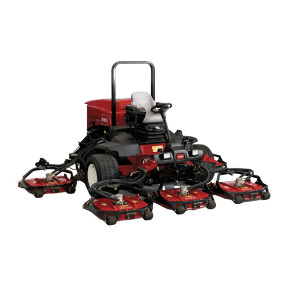
- Page 1 Form No. 02104SL Rev E ® Groundsmaster 4500-D/4700-D Original Instructions (EN)
- Page 2 THE TORO COMPANY 2018 This document and all information contained herein is the sole property of The Toro Company (and/or its affiliated companies). No intellectual property rights are granted by the delivery of this document or the disclosure of its content. This document shall not be...
- Page 3 Reader Comments The Toro Company Technical Assistance Center maintains a continuous effort to improve the quality and usefulness of its publications. To do this effectively, we encourage user feedback. Please comment on the completeness, accuracy, organization, usability, and readability of this manual by an e-mail to servicemanuals@toro.com...
- Page 4 NOTES...
-
Page 5: Service Manual
8111 Lyndale Avenue South machine. Bloomington, MN 55420--1196 The Toro Company reserves the right to change product specifications or this publication without notice. E The Toro Company - - 2002, 2003, 2005, 2007, 2018... - Page 6 This page is intentionally blank. Groundsmaster 4500--D/4700--D...
- Page 7 Table Of Contents Chapter 1 - - Safety Chapter 5 - - Electrical System General Safety Instructions ....1 -- 2 Electrical Schematics and Electrical Harness and Jacking Instructions .
- Page 8 This page is intentionally blank. Groundsmaster 4500--D/4700--D...
-
Page 9: General Safety Instructions 1
Chapter 1 Safety Table of Contents GENERAL SAFETY INSTRUCTIONS ... . JACKING INSTRUCTIONS ..... Before Operating . -
Page 10: General Safety Instructions
NEUTRAL and cutting units are DISENGAGED. machine and engine quickly. A replacement Operator’s 4. Since diesel fuel is highly flammable, handle it care- Manual is available on the Internet at www.Toro.com or fully: by sending the complete model and serial number to: A. -
Page 11: Jacking Instructions 1
Toro replacement parts and 6. Before disconnecting or performing any work on the accessories. Replacement parts and accessories made... -
Page 12: Jacking Instructions
Jacking Instructions CAUTION When changing attachments, tires, or perform- ing other service, use correct blocks, hoists, and jacks. Make sure machine is parked on a solid level surface such as a concrete floor. Prior to raising machine, remove any attach- ments that may interfere with the safe and prop- er raising of the machine. -
Page 13: Safety And Instruction Decals 1
Safety and Instruction Decals Numerous safety and instruction decals are affixed to the Groundsmaster 4500--D/4700--D. If any decal be- comes illegible or damaged, install a new decal. Decal part numbers are listed in your Parts Catalog. Groundsmaster 4500--D/4700--D Safety Page 1 - - 5... - Page 14 This page is intentionally blank. Safety Groundsmaster 4500--D/4700--D Page 1 - - 6...
-
Page 15: Product Records 2
Chapter 2 Product Records and Maintenance Table of Contents PRODUCT RECORDS ......Standard Torque for Dry, Zinc Plated, and MAINTENANCE . -
Page 16: Equivalents And Conversions 2
Equivalents and Conversions 0.09375 Product Records and Maintenance Groundsmaster 4500--D/4700--D Page 2 - - 2 Rev. D... -
Page 17: Torque Specifications 2
For critical applications, as determined reduced by 25% for lubricated fasteners to achieve by Toro, either the recommended torque or a torque that the similar stress as a dry fastener. Torque values may is unique to the application is clearly identified and spe- also have to be reduced when the fastener is threaded cified in this Service Manual. - Page 18 Standard Torque for Dry, Zinc Plated, and Steel Fasteners (Inch Series) Grade 1, 5, & SAE Grade 1 Bolts, Screws, Studs, & SAE Grade 5 Bolts, Screws, Studs, & SAE Grade 8 Bolts, Screws, Studs, & Thread Size 8 with Thin Sems with Regular Height Nuts Sems with Regular Height Nuts Sems with Regular Height Nuts...
- Page 19 Standard Torque for Dry, Zinc Plated, and Steel Fasteners (Metric Fasteners) Class 8.8 Bolts, Screws, and Studs with Class 10.9 Bolts, Screws, and Studs with Thread Size Thread Size Regular Height Nuts Regular Height Nuts Regular Height Nuts Regular Height Nuts (Class 8 or Stronger Nuts) (Class 10 or Stronger Nuts) M5 X 0.8...
- Page 20 Other Torque Specifications SAE Grade 8 Steel Set Screws Wheel Bolts and Lug Nuts Recommended Torque Thread Size Recommended Torque** Thread Size Thread Size Square Head Hex Socket 7/16 -- 20 UNF 65 + 10 ft--lb 88 + 14 N--m Grade 5 1/4 -- 20 UNC 140 + 20 in--lb...
-
Page 21: Table Of Contents
Chapter 3 Kubota Diesel Engine Table of Contents GENERAL INFORMATION ..... Radiator ........SPECIFICATIONS . -
Page 22: General Information
Service and repair parts for Kubota engines are sup- gine, V2003--T that is included at the end of this section. plied through your Authorized Toro Distributor. If no parts list is available, be prepared to provide your distrib- Most repairs and adjustments require tools which are utor with the Toro model and serial number. -
Page 23: Specifications
Specifications Item Description Make / Designation Kubota, 4--Cycle, 4 Cylinder, Water Cooled, Turbocharged, Diesel Engine Horse Power 58 HP (43.3 kW) @ 2600 RPM Bore mm (in.) 83.0 (3.27) Stroke mm (in.) 92.4 (3.64) Total Displacement cc (cu. in.) 1999 (122.12) Firing Order 1--3--4--2 Combustion Chamber... -
Page 24: Adjustments
Adjustments Engine Run Solenoid 1. When ignition switch is in the RUN position, the en- gine run solenoid should energize and position the fuel stop lever to within 1/16” (1.6 mm) of stop on the injec- tion pump. 2. If adjustment is needed, loosen lock nut and rotate the threaded end of the swivel until the lever is properly positioned. -
Page 25: Service And Repairs
Service and Repairs Air Filter System RIGHT FRONT VACUATOR DIRECTION Figure 3 1. Air cleaner hose 7. Hose clamp 12. Air cleaner body 2. Hose clamp 8. Air cleaner hose 13. Filter element 3. Air cleaner assembly 9. Hose clamp 14. -
Page 26: Exhaust System
Exhaust System 16 to 22 ft- -lb (21 to 29 N- -m) 16 to 22 ft- -lb (21 to 29 N- -m) RIGHT FRONT 16 to 22 ft- -lb (21 to 29 N- -m) Figure 5 1. Muffler 6. Lock nut 11. - Page 27 Removal CAUTION The muffler and exhaust pipe may be hot. To avoid possible burns, allow the engine and ex- haust system to cool before working on the muf- fler. 1. Park machine on a level surface, lower cutting units, stop engine, engage parking brake, and remove key from the ignition switch.
-
Page 28: Fuel System
Fuel System RIGHT FRONT Figure 7 1. Suction fitting 7. Bushing 13. Cap screw (4 used) 2. Fuel line clamp 8. Fuel level gauge 14. Hose clamp 3. Fuel hose 9. Grommet 15. Draincock 4. Return fitting 10. Fuel tank 16. -
Page 29: Fuel Tank Removal
Fuel Tank Removal Fuel Tank Installation 1. Park machine on a level surface, lower cutting units, 1. Install fuel tank to frame using Figure 7 as a guide. stop engine, engage parking brake, and remove key 2. Connect fuel hoses to the suction and return fittings from the ignition switch. -
Page 30: Radiator
Radiator RIGHT FRONT 9 10 Figure 8 1. Hydraulic fitting 15. Flange nut 28. O- -ring 2. Oil cooler 16. Tank bracket 29. O- -ring 3. Flange nut 17. Flat washer 30. Oil cooler mount plate 4. Radiator bracket 18. Flange head screw 31. - Page 31 Removal 4. Attach radiator fan shroud to the radiator with flange screws and flat washers. Make sure that clearance be- 1. Park machine on a level surface, lower cutting units, tween shroud and fan is at least .180” (4.6 mm) at all stop engine, engage parking brake, and remove key points.
-
Page 32: Engine
Engine 16 to 22 ft- -lb (21 to 29 N- -m) 16 to 22 ft- -lb (21 to 29 N- -m) RIGHT FRONT Figure 11 1. Engine 10. Bolt 18. Lock nut 2. Flange head screw 11. LH engine mount 19. -
Page 33: Engine Removal
Engine Removal 1. Park machine on a level surface, lower cutting units, stop engine, engage parking brake, and remove key from the ignition switch. Raise hood. 2. Remove battery strap and cover. Disconnect nega- tive battery cable first and then positive battery cable. Remove battery from machine. -
Page 34: Engine Installation
7. Disconnect fuel line from injection pump (Fig. 17). Cap fuel line and injector pump fuel inlet to prevent con- tamination. 8. Disconnect throttle cable from the speed control le- ver by removing the washer and lock nut. Loosen jam nut and take cable from mounting bracket (Fig. - Page 35 13.Install air cleaner assembly to the engine (see Air CAUTION Cleaner Installation). 14.Install exhaust system to machine (see Muffler One person should operate lift or hoist while the Installation). other person guides the engine into the machine. 15.Connect coolant hoses to the radiator. Make sure ra- diator drain is shut.
-
Page 36: Pump Adapter Plate
Pump Adapter Plate 17 to 21 ft- -lb (23 to 28 N- -m) 17 to 21 ft- -lb RIGHT (23 to 28 N- -m) FRONT 35 to 43 ft- -lb (48 to 58 N- -m) Figure 18 1. Engine 5. Plate pin (2 used) 9. - Page 37 Disassembly 1. Hydraulic pump assembly needs to be removed from engine before coupling can be serviced (see Pump As- sembly in Chapter 4 -- Hydraulic Systems). 2. Remove pump adapter plate, spring center coupling, and coupling spacer from engine using Figure 18 as a guide.
- Page 38 This page is intentionally blank. Kubota Diesel Engine (Rev. A) Groundsmaster 4500--D/4700--D Page 3 - - 18...
-
Page 39: Specifications 4
Chapter 4 Hydraulic System Table of Contents SPECIFICATIONS ......Flush Hydraulic System . - Page 40 Specifications Item Description Piston (Traction) Pump Variable displacement piston pump System Relief Pressure: Forward 5000 PSI (345 bar) System Relief Pressure: Reverse 5000 PSI (345 bar) Charge Pressure 260 PSI (17.9 bar) Gear Pump 3 section, positive displacement gear type pump Cutting Deck Relief Pressure 3500 PSI (241.5 bar) Steering Relief Pressure...
-
Page 41: General Information 4
General Information Hydraulic Hoses Hydraulic hoses are subject to extreme conditions such as pressure differentials during operation and exposure WARNING to weather, sun, chemicals, very warm storage condi- tions, or mishandling during operation and mainte- Before disconnecting or performing any work nance. - Page 42 SAE Straight Thread O- -Ring Port - - Non- -adjustable 1. Make sure both threads and sealing surfaces are free of burrs, nicks, scratches, or any foreign material. 2. Always replace the O--ring seal when this type of fit- ting shows signs of leakage. 3.
- Page 43 Towing Traction Unit IMPORTANT: If towing limits are exceeded, severe damage to the piston pump may occur. If it becomes necessary to tow (or push) the machine, tow (or push) in a forward direction only, at a speed below 3 mph (4.8 kph), and for a distance less than 1/4 mile (0.4 km).
-
Page 44: Hydraulic Schematics 4
Hydraulic Schematics Hydraulic System (Rev. A) Page 4 - - 6 Groundsmaster 4500--D/4700--D... - Page 45 Groundsmaster 4500--D/4700--D Page 4 - - 7 Hydraulic System (Rev. A)
-
Page 46: Hydraulic Flow Diagrams 4
Hydraulic Flow Diagrams Hydraulic System (Rev. A) Page 4 - - 8 Groundsmaster 4500--D/4700--D... - Page 47 Traction Circuit The traction circuit piston pump is a variable displace- Charge pressure is limited by a relief valve located in the ment pump that is directly coupled to the engine fly- filtration and charge control manifold. Charge pressure wheel. Pushing the top of the traction pedal engages a can be measured at the charge circuit pressure test port hydraulic servo valve which controls the variable dis- on the filtration and charge control manifold.
- Page 48 Hydraulic System (Rev. A) Page 4 - - 10 Groundsmaster 4500--D/4700--D...
-
Page 49: Lower Cutting Units
Lower Cutting Units A three section gear pump is coupled to the piston (trac- To lower a side cutting unit on the Groundsmaster tion) pump. The gear pump section (P3) farthest from 4700--D (deck #6 or #7), the appropriate lift lever on the the piston pump supplies hydraulic flow to both the lift/ lift/lower control valve is pushed to allow valve shift in the lower control valve and the steering control valve. - Page 50 Hydraulic System (Rev. A) Page 4 - - 12 Groundsmaster 4500--D/4700--D...
-
Page 51: Raise Cutting Units
Raise Cutting Units A three section gear pump is coupled to the piston (trac- To raise a side cutting unit on the Groundsmaster tion) pump. The gear pump section (P3) farthest from 4700--D (deck #6 or #7), the appropriate outer lift lever the piston pump supplies hydraulic flow to the lift/lower on the lift/lower control valve is pulled to allow valve shift control valve and the steering control valve. - Page 52 Hydraulic System (Rev. A) Page 4 - - 14 Groundsmaster 4500--D/4700--D...
-
Page 53: Mow Circuit
Mow Circuit Hydraulic flow for the mow circuit is supplied by two sec- stopping rate of the blade when the solenoid valves are tions of the gear pump (P1 and P2). Gear pump section de--energized as the PTO switch is turned OFF. Decks (P1) supplies hydraulic flow to decks 2, 3, and 5 (also 7 #6 and #7 are controlled by solenoid valve (SV2), logic on the GM 4700--D), while gear pump section (P2) -
Page 54: Cutting Deck Blade Braking
Cutting Deck Blade Braking When the operator turns the cutting decks OFF, propor- tional relief valve (PRV) shift occurs in the deck control manifold (Fig. 15). This shifted valve allows oil return to the oil cooler and gear pump. Hydraulic pressure is re- FROM TO OIL DECK... - Page 55 This page is intentionally blank. Groundsmaster 4500--D/4700--D Page 4 - - 17 Hydraulic System (Rev. A)
- Page 56 Hydraulic System (Rev. A) Page 4 - - 18 Groundsmaster 4500--D/4700--D...
-
Page 57: Steering Circuit
Steering Circuit A three section gear pump is coupled to the piston (trac- a left turn. The rotary meter ensures that the oil flow to tion) pump. The gear pump section (P3) supplies hy- the cylinder is proportional to the amount of the turning draulic flow to the steering control valve and the lift/lower on the steering wheel. -
Page 58: Special Tools
Special Tools Order these special tools from your Toro Distributor. Hydraulic Pressure Test Kit - - TOR47009 Use to take various pressure readings for diagnostic tests. Quick disconnect fittings provided attach directly to mating fittings on machine test ports without tools. A high pressure hose is provided for remote readings. -
Page 59: Hydraulic Test Fitting Kit
Hydraulic Test Fitting Kit - - TOR4079 This kit includes a variety of O--ring Face Seal fittings to enable you to connect test gauges into the system. The kit includes: tee’s, unions, reducers, plugs, caps, and male test fittings. Figure 21 Measuring Container - - TOR4077 Use this container for doing hydraulic motor efficiency testing (motors with case drain lines only). -
Page 60: Troubleshooting
Troubleshooting The charts that follow contain information to assist in Refer to the Testing section of this Chapter for precau- troubleshooting. There may possibly be more than one tions and specific test procedures. cause for a machine malfunction. Problem Possible Cause Hydraulic system operates hot. - Page 61 Problem Possible Causes Machine travels too far before stop- Traction linkage is out of adjustment. ping when the traction pedal is re- Piston pump servo control valve is damaged. leased. Traction pedal does not return to neutral. Four wheel drive will not engage. Electrical problem exists (see Chapter 5 -- Electrical System).
- Page 62 Problem Possible Causes Cutting units will not raise. Engine RPM is too low. Hydraulic oil level in reservoir is low. Lift cylinder(s) is (are) damaged. Lift arm pivots are binding. Relief valve for lift/lower circuit is stuck. Pilot valve in lift/lower manifold is damaged or sticking. Proportional valve in gear pump is faulty.
-
Page 63: Testing
Testing The most effective method for isolating problems in the WARNING hydraulic system is by using hydraulic test equipment such as pressure gauges and flow meters in the circuits during various operational checks (See the Special Before disconnecting or performing any work Tools section in this Chapter). -
Page 64: Test No. 1: Traction Circuit Charge Pressure
TEST NO. 1: Traction Circuit Charge Pressure (Using Pressure Gauge) FROM STEERING CONTROL AND LIFT SYSTEM CHARGE CIRCUIT TO TRACTION CONTROL MANIFOLD TO PTO (MOW) CIRCUIT TO LIFT/LOWER CIRCUIT TO STEERING CIRCUIT FROM PTO (MOW) CIRCUIT Working Pressure FROM STEERING CONTROL Low Pressure FROM PTO (MOW) CIRCUIT Return or Suction... - Page 65 Procedure for Traction Circuit Charge Pressure Test 1. Make sure hydraulic oil is at normal operating tem- perature by operating the machine for approximately 10 minutes. Make sure the hydraulic tank is full. 2. Park machine on a level surface with the cutting units lowered and off.
-
Page 66: Test No. 2: Traction Circuit Relief Pressure
TEST NO. 2: Traction Circuit Relief Pressure (Using Pressure Gauge) CHARGE CIRCUIT NOTE: FORWARD DIRECTION TEST SHOWN TO TRACTION CONTROL MANIFOLD TO LIFT/LOWER CIRCUIT TO STEERING CIRCUIT Working Pressure FROM PTO (MOW) CIRCUIT Low Pressure Return or Suction FROM STEERING CONTROL Flow FROM PTO (MOW) CIRCUIT Hydraulic System (Rev. - Page 67 Procedure for Traction Circuit Relief Pressure Test 1. Make sure hydraulic oil is at normal operating tem- perature by operating the machine for approximately 10 minutes. Make sure the hydraulic tank is full. CAUTION Move machine to an open area, away from people and obstructions.
-
Page 68: Test No. 3: Cutting Deck Circuit Pressure
TEST NO. 3: Cutting Deck Circuit Pressure (Using Pressure Gauge) GM 4500- -D Working Pressure Low Pressure Return or Suction Flow GM 4700- -D Hydraulic System (Rev. A) Page 4 - - 30 Groundsmaster 4500--D/4700--D... - Page 69 Procedure for Cutting Deck Circuit Pressure Test 1. Make sure hydraulic oil is at normal operating tem- perature by operating the machine for approximately 10 minutes. Make sure the hydraulic tank is full. 2. Park machine on a level surface with the cutting units lowered and off.
-
Page 70: Test No. 4: Cutting Deck Gear Pump Flow
TEST NO. 4: Cutting Deck Gear Pump Flow (Using Tester with Pressure Gauges and Flow Meter) NOTE: PUMP SECTION P1 TEST SHOWN FROM DECK CONTROL MANIFOLDS FROM LIFT/LOWER CIRCUIT Working Pressure Low Pressure Return or Suction Flow Hydraulic System (Rev. A) Page 4 - - 32 Groundsmaster 4500--D/4700--D... - Page 71 Procedure for Cutting Deck Gear Pump Flow Test 8. Flow indication should be approximately 11.5 GPM. NOTE: Over a period of time, the gears and wear plates 9. Shut off engine. in the pump can wear. A worn pump will by pass oil and 10.Disconnect flow tester from hydraulic hose and fit- make the pump less efficient.
-
Page 72: Test No. 5: Cutting Deck Manifold Relief Pressure
TEST NO. 5: Cutting Deck Manifold Relief Pressure (Using Tester with Pressure Gauges and Flow Meter) GM 4500- -D TESTER LOCATION FOR PUMP SECTION P1 TESTER LOCATION FOR PUMP SECTION P2 Working Pressure Low Pressure Return or Suction Flow GM 4700- -D TESTER LOCATION FOR PUMP SECTION P1... - Page 73 Procedure for Cutting Deck Manifold Relief Pressure Test Rotation Direction 1. Make sure hydraulic oil is at normal operating tem- perature by operating the machine for approximately 10 minutes. Make sure the hydraulic tank is full. 2. Park machine on a level surface with the cutting units lowered and off.
-
Page 74: Test No. 6: Cutting Deck Motor Case Drain Leakage
TEST NO. 6: Cutting Deck Motor Case Drain Leakage (Using Tester with Pressure Gauges and Flow Meter) GM 4500- -D DECK #2 TEST SHOWN TESTER LOCATION FOR DECK 2 MEASURING CONTAINER Working Pressure Low Pressure Return or Suction Flow Hydraulic System (Rev. A) Page 4 - - 36 Groundsmaster 4500--D/4700--D... - Page 75 Procedure for Cutting Deck Motor Case Drain 5. Sit on seat and start the engine. Move throttle to full Leakage Test speed (2800 + 50 RPM). Move PTO switch to ON. NOTE: Over a period of time, a deck motor can wear in- 6.
-
Page 76: Test No. 7: Steering Circuit Relief Pressure
TEST NO. 7: Steering Circuit Relief Pressure (Using Pressure Gauge) STEERING CYLINDER NOTE: LEFT TURN SHOWN 1180 STEERING CONTROL T VALVE TO LIFT/LOWER CIRCUIT CHARGE CIRCUIT TO PTO (MOW) CIRCUIT RESERVOIR 50 / 50 PROPORTIONAL FLOW DIVIDER TRACTION CIRCUIT FROM RESERVOIR FROM OIL FILTER... - Page 77 Procedure for Steering Circuit Relief Pressure Test 1. Make sure hydraulic oil is at normal operating tem- perature by operating the machine for approximately 10 minutes. Make sure the hydraulic tank is full. 2. Park machine on a level surface with the cutting units lowered and off.
-
Page 78: Test No. 8: Lift/Lower Circuit Relief Pressure
TEST NO. 8: Lift/Lower Circuit Relief Pressure (Using Pressure Gauge) GM 4500- -D SHOWN TO PTO (MOW) CIRCUIT TO STEERING CIRCUIT FROM PTO (MOW) CIRCUIT Working Pressure Low Pressure Return or Suction Flow Hydraulic System (Rev. A) Page 4 - - 40 Groundsmaster 4500--D/4700--D... - Page 79 Procedure for Lift/Lower Circuit Relief Pressure Test 1. Make sure hydraulic oil is at normal operating tem- perature by operating the machine for approximately 10 minutes. Make sure the hydraulic tank is full. 2. Park machine on a level surface with the cutting units lowered and off.
-
Page 80: Test No. 9: Steering And Lift/Lower Gear Pump Flow
TEST NO. 9: Steering and Lift/Lower Gear Pump Flow (Using Tester with Pressure Gauges and Flow Meter) NOTE: LIFT/LOWER GEAR PUMP FLOW TEST SHOWN TO STEERING CIRCUIT TO LIFT/LOWER CIRCUIT FORWARD 50 / 50 PROPORTIONAL FLOW DIVIDER TRACTION CIRCUIT FROM VALVE RESERVOIR FROM OIL... - Page 81 Procedure for Steering and Lift/Lower Gear Pump 7. If the total of the two flows is lower than 6.4 GPM or Flow Test a pressure of 1000 PSI could not be obtained, check for restriction in pump intake line. If intake line is not re- Output from the steering and lift/lower gear pump sec- stricted, remove gear pump and repair or replace as tion is equally divided by a proportional valve to provide...
-
Page 82: Test No. 10: Counterbalance (Rv1) Pressure
TEST NO. 10: Counterbalance (RV1) Pressure (Using Pressure Gauge) GM 4500- -D SHOWN TO STEERING CIRCUIT FROM PTO (MOW) CIRCUIT FROM PTO (MOW) CIRCUIT Working Pressure Low Pressure Return or Suction Flow Hydraulic System (Rev. A) Page 4 - - 44 Groundsmaster 4500--D/4700--D... - Page 83 Procedure for Counterbalance (RV1) Pressure Test 1. Make sure hydraulic oil is at normal operating tem- perature by operating the machine for approximately 10 minutes. Make sure the hydraulic tank is full. 2. Park machine on a level surface with the cutting units lowered and off.
- Page 84 TEST NO. 11: Rear Traction Circuit (RV5) Relief Pressure (Using Pressure Gauge) CHARGE CIRCUIT TO TRACTION CONTROL MANIFOLD TO LIFT/LOWER CIRCUIT TO STEERING CIRCUIT Working Pressure FROM PTO (MOW) CIRCUIT Low Pressure Return or Suction FROM STEERING CONTROL Flow FROM PTO (MOW) CIRCUIT Hydraulic System (Rev.
-
Page 85: Pressure
Procedure for Rear Traction Circuit (RV5) Relief Pressure Test 1. Make sure hydraulic oil is at normal operating tem- perature by operating the machine for approximately 10 minutes. Make sure the hydraulic tank is full. 2. Park machine on a level surface with the cutting units lowered and off. - Page 86 TEST NO. 12: Traction Circuit Reducing Valve (PR1) Pressure (Using Pressure Gauge) CHARGE CIRCUIT TO TRACTION CONTROL MANIFOLD TO LIFT/LOWER CIRCUIT TO STEERING CIRCUIT Working Pressure FROM PTO (MOW) CIRCUIT Low Pressure Return or Suction FROM STEERING CONTROL Flow FROM PTO (MOW) CIRCUIT Hydraulic System (Rev.
- Page 87 Procedure for Traction Circuit Reducing Valve (PR1) Pressure Test 1. Make sure hydraulic oil is at normal operating tem- perature by operating the machine for approximately 10 minutes. Make sure the hydraulic tank is full. 2. Park machine on a level surface with the cutting units lowered and off.
-
Page 88: Test No. 13: Traction Assist (Rv2) Pressure
TEST NO. 13: Traction Assist (RV2) Pressure (Using Pressure Gauges) GM 4500- -D SHOWN TO STEERING CIRCUIT FROM PTO (MOW) CIRCUIT FROM PTO (MOW) CIRCUIT Working Pressure Low Pressure Return or Suction Flow Hydraulic System (Rev. A) Page 4 - - 50 Groundsmaster 4500--D/4700--D... - Page 89 Procedure for Traction Assist (RV2) Pressure Test 1. Make sure hydraulic oil is at normal operating tem- perature by operating the machine for approximately 10 minutes. Make sure the hydraulic tank is full. 2. Park machine on a level surface with the cutting units lowered and off.
-
Page 90: Service And Repairs
Service and Repairs General Precautions for Removing and Installing Hydraulic System Components Before Repair or Replacement of Components After Repair or Replacement of Components 1. Before removing any parts from the hydraulic sys- 1. Check oil level in the hydraulic reservoir and add cor- tem, park machine on a level surface, engage parking rect oil if necessary. - Page 91 Flush Hydraulic System IMPORTANT: Flush the hydraulic system any time 6. Reconnect all hydraulic hoses, lines, and compo- there is a severe component failure or the system is nents that were disconnected while draining system. contaminated (oil appears milky, black, or contains NOTE: Use only hydraulic fluids specified in the Trac- metal particles).
-
Page 92: Charge Hydraulic System
Charge Hydraulic System NOTE: When initially starting the hydraulic system with 11. After the hydraulic system starts to show signs of fill, new or rebuilt components such as motors, pumps, or actuate lift control lever until the lift cylinder rod moves lift cylinders, it is important that the hydraulic system be in and out several times. - Page 93 This page is intentionally blank. Groundsmaster 4500--D/4700--D Page 4 - - 55 Hydraulic System (Rev. A)
-
Page 94: Gear Pump
Gear Pump 85 to 95 ft- -lb (115 to 128 N- -m) RIGHT FRONT Figure 54 1. Flat washer 12. O- -ring 23. O- -ring 2. Cap screw 13. 90 hydraulic fitting 24. O- -ring 3. 90 hydraulic fitting 14. Suction hose 25. - Page 95 Removal Installation 1. Park machine on a level surface, lower cutting units, 1. Lubricate new o--rings with clean hydraulic oil and stop engine, engage parking brake, and remove key position on gear pump. from the ignition switch. 2. Slide coupler onto the piston pump output shaft. 2.
-
Page 96: Gear Pump Service
Gear Pump Service 25 to 28 ft- -lb (34 to 38 N- -m) 18 17 21 to 24 ft- -lb (29 to 33 N- -m) 21 to 24 ft- -lb (29 to 33 N- -m) Figure 55 1. Shaft seal 11. - Page 97 3. Remove pump from vise, hold pump in hands and Inspection bump shaft against wooden block to separate front 1. Clean and dry all pump components. Remove nicks pump sections. Front body (10) will remain with either and burrs from all parts with emery cloth. front plate (15) or front adapter plate (23).
- Page 98 Reassembly 10.Install key (17) in slot of drive gear shaft. Dip slip fit gear (18) in clean hydraulic oil and slide on shaft and into It is important that the relationship of the backplate, gear pocket of middle body (19). Check key for proper adapter plates, bodies, wear plates and front plate is alignment.
- Page 99 This page is intentionally blank. Groundsmaster 4500--D/4700--D Page 4 - - 61 Hydraulic System (Rev. A)
-
Page 100: Piston (Traction) Pump
Piston (Traction) Pump 85 to 95 ft- -lb (115 to 128 N- -m) RIGHT FRONT Figure 56 1. Flat washer 14. Suction hose 26. Gear pump assembly 2. Cap screw 15. Suction hose 27. Piston pump assembly 3. 90 hydraulic fitting 16. - Page 101 Removal Installation 1. Park machine on a level surface, lower cutting units, 1. Carefully lower piston pump into the machine and stop engine, engage parking brake, and remove key position it to the engine adapter plate. Support pump to from the ignition switch. prevent it from falling while installing two (2) cap screws and washers securing piston pump to engine adapter 2.
-
Page 102: Piston (Traction) Pump Service
Piston (Traction) Pump Service 100 to 110 ft- -lb 27 to 31 ft- -lb (136 to 149 N- -m) (37 to 42 N- -m) 100 to 110 ft- -lb (136 to 149 N- -m) 150 to 160 in- -lb (17 to 18 N- -m) 4 to 6 ft- -lb (5 to 8 N- -m) 40 to 48 in- -lb... - Page 103 Disassembly (3), thrust race (12), thrust bearing (13), second thrust race (12), and second retaining ring (3) from drive shaft Work in a clean area as cleanliness is extremely impor- (21). tant when repairing hydraulic pumps. Thoroughly clean the outside of pump. After cleaning, remove port plugs 12.Remove the two cap screws (42) that secure cradle and drain oil from pump.
- Page 104 3. Inspect camplate assembly: A. The finish on the piston shoe surfaces of the cam- plate (11) should show no signs of scoring. B. Inspect camplate (11) bushing surface for wear. Also inspect surface for coating transfer from bush- ing. 4.
- Page 105 8. Place exterior retaining ring (3), thrust race (12), 16.Apply a small amount of petroleum jelly to the steel thrust bearing (13), second thrust race (12), and second side of valve plate (18) to hold in place for installation. retaining ring (3) onto drive shaft (21). Position washer Aligning the index pin, place the valve plate (18) in posi- (24) and shaft seal (25) onto shaft.
-
Page 106: Piston Pump Manual Servo Control Assembly
Piston Pump Manual Servo Control Assembly 44 to 52 ft- -lb (60 to 70 N- -m) 17 to 26 in- -lb (2 to 3 N- -m) 28 to 34 in- -lb (3.2 to 3.8 N- -m) Figure 62 1. Plug 9. - Page 107 5. Apply Loctite #242 or equivalent to set screw (18) 5. Test the switch by moving the control arm to the det- and install into control housing. Adjust set screw until it ent position, the light should be on. Move the control arm bottoms out on input shaft and back out one--quarter out of detent, the light should go off.
-
Page 108: Hydraulic Control Manifolds: 2 Wheel/4 Wheel Drive, Filtration And Charge, Power Down And Traction Assist
Hydraulic Control Manifolds: 2 Wheel/4 Wheel Drive, Filtration and Charge, Power Down and Traction Assist RIGHT FRONT Figure 64 1. Power down/traction assist manifold 4. Flange head screw (4 used) 6. Cap screw (2 used) 2. Flange head screw (3 used) 5. - Page 109 Removal Installation NOTE: The ports on the manifolds are marked for easy 1. Install hydraulic manifold to the frame using Figure identification of components. Refer to the Hydraulic 64 as guide. Schematics to identify the function of the hydraulic lines 2.
-
Page 110: Hydraulic Control Manifold Service: 2 Wheel/4 Wheel Drive Control
Hydraulic Control Manifold Service: 2 Wheel/4 Wheel Drive Control 80 to 90 ft- -lb (108 to 122 N- -m) 16 17 80 to 90 ft- -lb (108 to 122 N- -m) 16 17 60 to 70 ft- -lb (81 to 95 N- -m) 35 to 40 ft- -lb PLUG TORQUE (47 to 54 N- -m) - Page 111 5. Visually inspect cartridge valve for damaged sealing 7. Reinstall the cartridge valve: surfaces and contamination. A. Lubricate new seal kit components with clean hy- A. Contamination may cause valves to stick or hang draulic oil and install on valve. The o--rings, sealing up.
-
Page 112: Hydraulic Control Manifold Service: Filtration And Charge Control
Hydraulic Control Manifold Service: Filtration and Charge Control 35 to 40 ft- -lb (47 to 54 N- -m) 60 to 70 ft- -lb (81 to 95 N- -m) PLUG TORQUE SAE #4: 6 to 10 ft- -lb (8 to 13 N- -m) SAE #5: 10 to 15 ft- -lb (13 to 20 N- -m) SAE #6: 15 to 20 ft- -lb (20 to 27 N- -m) SAE #10: 35 to 40 ft- -lb (48 to 54 N- -m) - Page 113 Hydraulic Control Manifold Service: Power Down and Traction Assist (GM 4500- -D) 25 ft- -lb (33.9 N- -m) 25 ft- -lb (33.9 N- -m) 20 ft- -lb (27.1 N- -m) 20 ft- -lb (27.1 N- -m) Figure 67 1. Manifold body 4.
- Page 114 Hydraulic Control Manifold Service: Power Down and Traction Assist (GM 4700- -D) 25 ft- -lb (33.9 N- -m) 20 ft- -lb (27.1 N- -m) 25 ft- -lb (33.9 N- -m) 20 ft- -lb 20 ft- -lb (27.1 N- -m) (27.1 N- -m) 20 ft- -lb (27.1 N- -m) Figure 68...
- Page 115 This page is intentionally blank. Groundsmaster 4500--D/4700--D Page 4 - - 77 Hydraulic System (Rev. A)
-
Page 116: Hydraulic Control Manifold: Deck Drive
Hydraulic Control Manifold: Deck Drive (GM 4500- -D) RIGHT FRONT Figure 69 1. Hydraulic manifold: decks 2, 3, & 5 7. 90 hydraulic fitting 13. O- -ring 2. Hydraulic adapter 8. Quick fitting 14. O- -ring 3. 90 hydraulic fitting 9. -
Page 117: Hydraulic Control Manifold Service: Deck Drive (Gm 4500--D)
Hydraulic Control Manifold Service: Deck Drive (GM 4500- -D) 4 to 5 ft- -lb (5.4 to 6.8 N- -m) 165 in- -lb (18.6 N- -m) 20 ft- -lb (27.1 N- -m) 25 ft- -lb (33.9 N- -m) 25 ft- -lb (33.9 N- -m) 198 in- -lb (22.4 N- -m) -
Page 118: Hydraulic Control Manifold: Deck Drive
Hydraulic Control Manifold: Deck Drive (GM 4700- -D) RIGHT FRONT Figure 71 1. Hydraulic manifold: decks 2, 3, 5, & 7 7. 90 hydraulic fitting 13. O- -ring 2. Hydraulic adapter 8. Quick fitting 14. O- -ring 3. 90 hydraulic fitting 9. -
Page 119: Hydraulic Control Manifold Service: Deck Drive (Gm 4700--D)
Hydraulic Control Manifold Service: Deck Drive (GM 4700- -D) 4 to 5 ft- -lb 20 ft- -lb (5.4 to 6.8 N- -m) 20 ft- -lb (27.1 N- -m) (27.1 N- -m) 25 ft- -lb (33.9 N- -m) 25 ft- -lb (33.9 N- -m) 198 in- -lb (22.4 N- -m) -
Page 120: Rear Axle Motor
Rear Axle Motor Arrows on side of motor case point up 59 to 73 ft- -lb (80 to 99 N- -m) RIGHT FRONT Figure 73 1. Axle motor 5. O- -ring 8. 90 hydraulic fitting 2. O- -ring 6. Hydraulic fitting 9. - Page 121 Removal Installation 1. Park machine on a level surface, lower cutting units, 1. If removed, install pinion gear to axle motor. stop engine, engage parking brake, and remove key 2. Install o--ring onto motor. Position motor to rear axle from the ignition switch. assembly making sure that arrows on the side of motor 2.
-
Page 122: Front Wheel Motors
Front Wheel Motors 23 24 75 to 85 ft- -lb (101 to 115 N- -m) Arrows on side of RIGHT motor case point up FRONT Figure 74 1. Flange head screw 10. O- -ring 18. O- -ring 2. Splined brake shaft 11. - Page 123 Removal Installation 1. Park machine on a level surface, lower cutting units, 1. Position wheel motor to brake assembly making sure stop engine, engage parking brake, and remove key that arrows on the side of motor case point upward. from the ignition switch. 2.
-
Page 124: Rear Axle/Front Wheel Motor Service
Rear Axle/Front Wheel Motor Service 15 to 18 ft- -lb (20 to 24 N- -m) FRONT WHEEL MOTOR SHOWN Figure 75 1. Drive shaft 8. Shaft seal (front motor only) 15. Roll pin 2. Backplate 9. Retaining ring 16. Bearing 3. - Page 125 4. Remove motor from vise and remove rotating as- 2. If necessary, install new needle bearing (17) in hous- sembly (4) from motor housing. ing (3) with numbered end of the bearing outward. 5. Remove the camplate insert (5) from housing. Use 3.
- Page 126 This page is intentionally blank. Hydraulic System (Rev. A) Page 4 - - 88 Groundsmaster 4500--D/4700--D...
-
Page 127: Cutting Deck Motor
Cutting Deck Motor The hydraulic motors used on all cutting decks are the same. Removal 1. Park machine on a level surface, lower cutting units, stop engine, engage parking brake, and remove key from the ignition switch. 2. Read the General Precautions for Removing and Installing Hydraulic System Components at the begin- ning of the Service and Repairs section of this chapter. -
Page 128: Cutting Deck Motor Service
Cutting Deck Motor Service 38 to 43 ft- -lb (51 to 58 N- -m) 30 to 35 ft- -lb (41 to 47 N- -m) Figure 78 1. Outer shaft seal 6. Front bearing block 11. Idler gear 2. Inner shaft seal 7. - Page 129 7. Carefully remove housing by lifting housing straight 4. Inspect bearing blocks for the following: up. Make sure the rear bearing block remains on the A. Bearing areas should not have excessive wear or drive and idler gear shafts. Remove and discard o--rings scoring.
- Page 130 8. Lubricate the drive gear shaft with clean hydraulic oil. Noting the open and closed sides of the front bearing block, insert the drive end of the drive shaft through the bearing block with the pressure seal side down. Careful- ly install shaft into front flange.
- Page 131 Relief Valve Service IMPORTANT: Do not remove the relief valve as- sembly unless testing shows it to be faulty. 1. When removing or installing the relief valve, motor should be removed from deck and positioned horizon- tally with the relief valve pointed down (Fig. 83). This process will prevent the relief valve from falling into mo- tor passages.
-
Page 132: Lift/Lower Control Valve (Gm 4500--D)
Lift/Lower Control Valve (GM 4500- -D) RIGHT FRONT Figure 84 1. Control valve assembly (1 spool) 10. Lift lever 18. Insert nut 2. O- -ring 11. Control knob 19. Flange nut 3. Hydraulic adapter 12. Curved washer 20. Extension spring 4. - Page 133 Removal Installation 1. Park machine on a level surface, lower cutting units, 1. Install control valve using Figure 86 as a guide. stop engine, engage parking brake, and remove key 2. Make sure hydraulic tank is full. Add correct oil if nec- from the ignition switch.
-
Page 134: Lift/Lower Control Valve Service (Gm 4500--D)
Lift/Lower Control Valve Service (GM 4500- -D) 10 to 12 ft- -lb 4 to 5 ft- -lb (13 to 16 N- -m) (5 to 7 N- -m) 30 to 35 ft- -lb (41 to 48 N- -m) 30 to 35 ft- -lb (41 to 48 N- -m) 20 to 25 ft- -lb (27 to 33 N- -m) - Page 135 NOTE: Cleanliness is extremely important when Assembly repairing hydraulic components. Work in a clean area. 1. Thoroughly clean and dry all parts. Apply a light coat- Before disassembly, drain the oil, then plug the ports ing of clean hydraulic oil to parts prior to assembly. and thoroughly clean the exterior.
-
Page 136: Lift/Lower Control Valve (Gm 4700--D)
Lift/Lower Control Valve (GM 4700- -D) RIGHT FRONT Figure 86 1. Control valve assembly (3 spool) 10. Spacer 19. Lock nut 2. O- -ring 11. Left lift lever 20. Flange head screw 3. Hydraulic adapter 12. Control knob (3 used) 21. - Page 137 Removal Installation 1. Park machine on a level surface, lower cutting units, 1. Install control valve using Figure 86 as a guide. stop engine, engage parking brake, and remove key 2. Make sure hydraulic tank is full. Add correct oil if nec- from the ignition switch.
-
Page 138: Lift/Lower Control Valve Service (Gm 4700--D)
Lift/Lower Control Valve Service (G 4700- -D) 30 to 35 ft- -lb (41 to 48 N- -m) 10 to 12 ft- -lb (13 to 16 N- -m) 4 to 5 ft- -lb (5 to 7 N- -m) 20 to 25 ft- -lb (27 to 33 N- -m) 30 to 35 ft- -lb (41 to 48 N- -m) - Page 139 NOTE: Cleanliness is extremely important when Assembly repairing hydraulic components. Work in a clean area. 1. Thoroughly clean and dry all parts. Apply a light coat- Before disassembly, drain the oil, then plug the ports ing of clean hydraulic oil to parts prior to assembly. and thoroughly clean the exterior.
-
Page 140: Steering Valve
Steering Valve 20 to 26 ft- -lb (28 to 35 N- -m) RIGHT FRONT Figure 88 1. Steering valve 8. Steering column bracket 15. Hydraulic adapter 2. Steering column 9. Flange head screw 16. O- -ring 3. Flange head screw (3 used) 10. - Page 141 Removal Installation 1. Park machine on a level surface, lower cutting units, 1. Install steering valve using Figure 88 as a guide. stop engine, engage parking brake, and remove key 2. Make sure hydraulic tank is full. Add correct oil if nec- from the ignition switch.
-
Page 142: Steering Valve Service
Steering Valve Service 150 in- -lb (17 N- -m) 140 to 160 in- -lb (16 to 18 N- -m) Figure 89 1. Steering valve housing 9. Cap screw 17. Geroter drive 2. Dust seal 10. End cap 18. Wear plate 3. - Page 143 8. Put the thrust bearing and races into the housing. CAUTION The thrust bearing goes between the two races (Fig. 90). IMPORTANT: Do not damage the dust or quad seals The centering springs are under tension. Re- when installing the spool and sleeve assembly. move the retaining ring carefully.
-
Page 144: Lift Cylinders: Decks #1, #4, And #5
Lift Cylinders: Decks #1, #4, and #5 RIGHT FRONT Figure 91 1. Lift arm (deck #4) 6. O- -ring 10. Lift cylinder (deck #4) 2. Flange nut 7. 90 hydraulic fitting 11. Lift cylinder (deck #1) 3. Lift arm (deck #1) 8. - Page 145 Removal (Fig. 91) 1. Park machine on a level surface, lower cutting units, #4 Deck #1 Deck #5 Deck stop engine, engage parking brake, and remove key from the ignition switch. 2. Read the General Precautions for Removing and Installing Hydraulic System Components at the begin- ning of the Service and Repairs section of this chapter.
-
Page 146: Lift Cylinders: Decks #2 And #3
Lift Cylinders: Decks #2 and #3 RIGHT FRONT Figure 93 1. Lift arm (deck #2 shown) 6. O- -ring 11. Lift cylinder 2. Cylinder pin 7. Retaining ring 12. Flange nut 3. Flange head screw 8. Cylinder pin 13. Rotation stop 4. - Page 147 Removal (Fig. 93) 1. Park machine on a level surface, lower cutting units, #4 Deck #1 Deck #5 Deck stop engine, engage parking brake, and remove key from the ignition switch. 2. Read the General Precautions for Removing and Installing Hydraulic System Components at the begin- ning of the Service and Repairs section of this chapter.
-
Page 148: Lift Cylinders: Decks #6 And #7 (Gm 4700--D)
Lift Cylinders: Decks #6 and #7 (GM 4700- -D) RIGHT FRONT Figure 95 1. Retaining ring 7. Plastic roller 12. O- -ring 2. Cylinder pin 8. Rear link 13. Grease fitting 3. Thrust washer 9. Lock nut 14. O- -ring 4. - Page 149 Removal (Fig. 95) 1. Park machine on a level surface, lower cutting units, #4 Deck #1 Deck #5 Deck stop engine, engage parking brake, and remove key from the ignition switch. 2. Read the General Precautions for Removing and Installing Hydraulic System Components at the begin- ning of the Service and Repairs section of this chapter.
-
Page 150: Lift Cylinder Service
Lift Cylinder Service Figure 97 1. Barrel with clevis 5. Rod seal 9. O- -ring 2. Collar 6. O- -ring 10. Uni- -ring 3. Shaft with clevis 7. Back- -up ring 11. Piston 4. Dust seal 8. Head 12. Locking nut Hydraulic System (Rev. - Page 151 Disassembly Assembly 1. Remove oil from lift cylinder into a drain pan by slowly 1. Make sure all parts are clean before reassembly. pumping the cylinder shaft. Plug both ports and clean 2. Coat new O--rings, Uni--ring, rod seal, back--up ring, the outside of the cylinder.
-
Page 152: Steering Cylinder
Steering Cylinder 100 to 125 ft- -lb (135 to 169 N- -m) RIGHT 100 to 125 ft- -lb (135 to 169 N- -m) FRONT Figure 98 1. Steering cylinder 6. Grease fitting 11. Ball joint spacer 2. Ball joint 7. 90 hydraulic fitting 12. - Page 153 Removal Installation 1. Park machine on a level surface, lower cutting units, 1. Place a washer onto each ball joint. Slide ram end stop engine, engage parking brake, and remove key ball joint through hole on steering arm. Secure with axle from the ignition switch.
-
Page 154: Steering Cylinder Service
Steering Cylinder Service Figure 99 1. Butt and tube assembly 5. Lock nut 9. O- -ring 2. Shaft 6. O- -ring 10. U- -cup 3. Piston rod assembly 7. PTFE seal 11. Wiper 4. Gland 8. O- -ring Rev. C Hydraulic System (Rev. - Page 155 Disassembly Assembly IMPORTANT: To prevent damage when clamping 1. Use a complete repair kit when rebuilding the cylin- cylinder barrel or rod in a vise, clamp only on pivotal der. Put a coating of clean hydraulic oil on all new seals, ends.
-
Page 156: Hydraulic Reservoir
Hydraulic Reservoir 80 to 87 ft- -lb (108 to 118 N- -m) RIGHT FRONT 30 to 60 in- -lb (3.4 to 6.8 N- -m) Figure 100 1. Hydraulic reservoir cap 8. O- -ring 14. Flat washer (3 used) 2. O- -ring 9. -
Page 157: Hydraulic Oil Cooler
Hydraulic Oil Cooler Removal CAUTION The radiator and oil cooler may be hot. To avoid possible burns, allow the engine and cooling systems to cool before working on the oil cooler. 1. Park machine on a level surface, lower cutting units, stop engine, engage parking brake, and remove key Figure 101 from the ignition switch. - Page 158 This page is intentionally blank. Hydraulic System (Rev. A) Page 4 - - 120 Groundsmaster 4500--D/4700--D...
-
Page 159: Special Tools 5
Chapter 5 Electrical System Table of Contents ELECTRICAL SCHEMATICS AND ELECTRICAL Hour Meter ....... . HARNESS AND CONNECTORS DRAWINGS . -
Page 160: Electrical Schematics And Electrical Harness And Connectors Drawings
Multimeter The multimeter can test electrical components and cir- cuits for current, resistance, or voltage. NOTE: Toro recommends the use of a DIGITAL Volt-- Ohm--Amp multimeter when testing electrical circuits. The high impedance (internal resistance) of a digital me- ter in the voltage mode will make sure that excess cur- rent is not allowed through the meter. -
Page 161: Troubleshooting
Troubleshooting For effective troubleshooting and repairs, you must have a good understanding of the electrical circuits and CAUTION components used on this machine (see Chapter 9 -- Electrical Diagrams). Remove all jewelry, especially rings and If the machine has any interlock switches by--passed, watches, before doing any electrical trouble- shooting or testing. -
Page 162: General Run & Transport Problems
Starting Problems (continued) Problem Possible Causes Engine cranks, but does not start. Engine is not cranking fast enough. Engine run solenoid, circuit wiring, or fuel pump is faulty. The problem is not electrical (see Chapter 3 -- Kubota Engines). Starter cranks, but should not when the traction pedal The traction neutral switch is out of adjustment. -
Page 163: Cutting Unit Operating Problems
Cutting Unit Operating Problems Cutting units run, but should not, when raised. Units The cutting deck position switch or circuit wiring is shut off with PTO switch. faulty. The cutting deck lift/lower switch or circuit wiring is faulty. Cutting units run, but should not, when raised. Units do The deck position switch, cutting deck lift/lower switch, not shut off with the PTO switch. -
Page 164: Electrical System Quick Checks
Electrical System Quick Checks Battery Test (Open Circuit Test) Use a multimeter to measure the voltage between the Voltage Measured Battery Charge Level battery terminals. 12.68 V (or higher) Fully charged (100%) Set multimeter to the DC volts setting. The battery 12.45 V 75% charged should be at a temperature of 60 to 100... -
Page 165: Component Testing
Component Testing For accurate resistance and/or continuity checks, elec- trically disconnect the component being tested from the CAUTION circuit (e.g. unplug the ignition switch connector before doing a continuity check). When testing electrical components for continu- NOTE: For engine component testing information, see ity with a multimeter (ohms setting), make sure the Kubota Workshop Manual, Diesel Engine, V2003--T that power to the circuit has been disconnected. -
Page 166: Fuses
Fuses The fuse block is located under the operator’s control panel. Machines with serial numbers below 220999999 have four (4) fuses (Fig. 5). Machines with serial num- bers above 230000000 have six (6) fuses (Fig. 6). Identification, Function, and Wiring The fuses are held in the fuse block. -
Page 167: Indicator Lights
Indicator Lights Testing Indicator Lights 1. Apply 12 VDC to terminals 1A and 2A. 2. Ground terminals 1B and 2B. 3. Both indicator lights should light. Engine Oil Pressure Light The oil pressure light should come on when the ignition switch is in the ON position with the engine not running. -
Page 168: Pto And Hi--Lo Speed Control Switches
PTO and Hi- -Lo Speed Control Switches The PTO and Hi--Lo Speed Control Switches are lo- cated on the control console (Fig. 10). These rocker switches have common switching logic. The switch terminals are marked as shown in Figure 11. The circuitry of these switches is shown in the chart be- low. -
Page 169: Seat Switch
Seat Switch The seat switch is normally open and closes when the operator is on the seat. If the traction system or PTO switch is engaged when the operator raises out of the seat, the engine will stop. The seat switch and its electri- cal connector are located directly under the seat. -
Page 170: Cutting Deck Position Switch
Cutting Deck Position Switch The cutting deck position switch is a normally open prox- imity switch that is located on the traction unit frame (Fig. 14). The sensing plate is located on the cutting deck lift arm. The GM 4500--D uses two cutting deck position switches: for decks 4 and 5. -
Page 171: Cutting Deck Lift/Lower Switch
Cutting Deck Lift/Lower Switch The lift/lower switch is a normally open proximity switch that is closed when a lift lever is in the neutral position. When a lift lever is moved to raise, the lift/lower switch opens. Each lift lever is equipped with a cutting deck lift/ lower switch. -
Page 172: Ramp--Up Module
Ramp- -up Module The ramp--up module is located under the console cover (Fig. 19). The ramp--up module is used to prevent hydraulic spikes that could affect cutting system hydraulic compo- nents. As the PTO relay for decks #1 to #5 is energized, the ramp--up module provides a gradual, increasing cur- rent flow to the cutting deck solenoid valves. -
Page 173: Hour Meter
Hour Meter The meter is located on the control console next to the operator seat. Hobbs 1. Connect the positive (+) terminal of a 12 VDC source QUARTZ to the positive (+) terminal of the hour meter. 0 0 0 0 HOURS 2. - Page 174 Start, Neutral, Seat, Cutting Deck, Parking Brake, and High Temperature Relays The relays are located under the console cover (Fig. 23). The wiring harness is tagged to identify each relay. NOTE: Machines with serial numbers above 230000000 use a standard control module to monitor several switches.
-
Page 175: Hydraulic Valve Solenoids
Hydraulic Valve Solenoids The Groundsmaster 4500--D has three hydraulic valve solenoids: one on each cutting deck manifold and one on the traction manifold. The Groundsmaster 4700--D has five solenoids: two on each cutting deck manifold and one on the traction manifold. Testing of these sole- noids can be done with the solenoid on the hydraulic valve. -
Page 176: Engine Run Solenoid
Engine Run Solenoid The engine run solenoid must be energized for the en- gine to run. The solenoid is mounted on the engine block near the injection pump. In Place Testing NOTE: Prior to taking small resistance readings with a digital multimeter, short the meter test leads together. -
Page 177: Fuel Pump
Fuel Pump The fuel pump is attached to the frame near the fuel pre-- filter (Fig. 29). IMPORTANT: When testing fuel pump, make sure that pump is not operated without fuel. Fuel Pump Capacity Test 1. Park machine on a level surface, lower cutting units, stop engine, and engage parking brake. -
Page 178: Glow Controller
Glow Controller The glow controller is located under the console cover. NOTE: Refer to Chapter 9 -- Electrical Schematics and Diagrams when troubleshooting the controller. Controller Operation 1. When the ignition switch is placed in the ON position, the controller energizes the glow plugs and lights up the glow lamp for 7 to 10 seconds. -
Page 179: Temperature Sender
B. Screw sender into the water flange. Torque send- er from 16 to 20 ft--lb (21.7 to 27.1 N--m). C. Reconnect gray wire to sender. Apply skin--over grease (Toro Part No. 505--47) to sender terminal. 5. Fill engine cooling system (see Traction Unit Opera- tor’s Manual). -
Page 180: Temperature Gauge
Temperature Gauge The temperature gauge can be tested using a new gauge as a substitute or by the use of a DC voltage source and a variable resistance box. Temperature Gauge Test CAUTION VARIABLE RESISTANCE Make sure the voltage source is turned OFF be- fore connecting it to the electrical circuit to avoid electrical shock and prevent damaging the 14 VDC + 0.01 VDC... -
Page 181: High Temperature Shutdown Switch
High Temperature Shutdown Switch The high temperature shutdown switch is located near the glow plug connection on the engine cylinder head (Fig. 36). There is a blue/white wire attached to the switch. The high temperature shutdown switch is designed to shut the engine off when engine coolant temperature reaches an unsafe level. -
Page 182: Traction Neutral Switch
Traction Neutral Switch The traction neutral switch is closed when the traction pedal is in the neutral position and opens when the pedal is depressed in either direction. The switch is located on the right side of the piston (traction) pump. Test the switch by disconnecting the wires from the switch terminals and connecting a continuity tester across the two switch terminals. -
Page 183: Diode Circuit Board
Diode Circuit Board The diode circuit board contains four diodes (Fig. 40) and is located under the console housing. Diode D1--A provide logic for the interlock switches. Diodes D1--C, D1--B (GM 4700--D right deck), and D1--D (GM 4700--D D1--D left deck) are used for circuit protection from voltage D1--A spikes when PTO relays are de--energized. -
Page 184: Standard Control Module
Standard Control Module Groundsmaster 4500--D and 4700--D machines with Serial Numbers above 230000000 are equipped with a Standard Control Module to monitor and control electri- cal components required for safe operation. This Mod- ule is located under the console cover. Inputs from the neutral, parking brake, PTO, start (igni- tion), and high temperature switches are monitored by the Module. -
Page 185: Service And Repairs
A. Clean battery by washing entire case with a solu- tion of baking soda and water. Rinse with clear water. B. Coat battery posts and cable connectors with skin--over grease (Toro Part No. 505-165) or petro- leum jelly to prevent corrosion. Rev. D... -
Page 186: Battery Service
Battery Service The battery is the heart of the electrical system. With regular and proper service, battery life can be extended. Additionally, battery and electrical component failure can be prevented. CAUTION When working with batteries, use extreme cau- tion to avoid splashing or spilling electrolyte. Electrolyte can destroy clothing and burn skin or eyes. - Page 187 C. If the difference between the highest and lowest H. Using the table below, determine the minimum cell specific gravity is 0.050 or greater or the lowest voltage for the cell temperature reading: cell specific gravity is less than 1.225, charge the bat- tery.
- Page 188 2. Determine the charging time and rate using the 3. Following the manufacturer’s instructions, con- manufacturer’s battery charger instructions or the nect the charger cables to the battery. Make sure a good following table. connection is made. 4. Charge the battery following the manufacturer’s Battery Battery Charge Level instructions.
-
Page 189: Adjustments 6
Chapter 6 Axles, Planetaries, and Brakes Table of Contents SPECIFICATIONS ......Rear Axle Assembly . -
Page 190: Specifications
Specifications Item Specification Wheel lug nut torque (front and rear) 85 to 100 ft--lb (115 to 135 N--m) Steering cylinder bolt torque 100 to 125 ft--lb (135 to 169 N--m) Planetary brake housing and wheel motor 75 to 85 ft--lb (101 to 115 N--m) mounting screw torque Rear wheel toe--in .125 in (3.2 mm) -
Page 191: Adjustments
Adjustments See Traction Unit Operator’s Manual for adjustment procedures for Groundsmaster 4500--D and Ground- smaster 4700--D axles, planetaries, and brakes. Groundsmaster 4500--D/4700--D Page 6 - - 3 Axles, Planetaries, and Brakes (Rev. B) -
Page 192: Service And Repairs
Service and Repairs Brake Assembly RIGHT FRONT 75 to 85 ft- -lb (101 to 115 N- -m) 85 to 100 ft- -lb (115 to 135 N- -m) Figure 1 1. Flange head screw 8. Compression spring 14. Flat washer 2. Splined brake shaft 9. - Page 193 Remove Brake Assembly (Fig. 1) 3. Install flange head screws (11) to secure brake as- sembly to frame. Tighten screws in a crossing pattern to 1. Park machine on a level surface and raise cutting a torque from 75 to 85 ft--lb (101 to 115 N--m). units to allow easier access to front brake assembly.
-
Page 194: Brake Inspection And Repair
Brake Inspection and Repair Figure 4 1. Brake housing (LH shown) 6. Hitch pin 11. Rotating actuator 2. Seal 7. Stationary disc 12. Extension spring 3. Pull rod 8. Rotating disc 13. Ball 4. Clevis pin 9. Retaining ring 14. Plug 5. - Page 195 This page is intentionally blank. Groundsmaster 4500--D/4700--D Page 6 - - 7 Axles, Planetaries, and Brakes (Rev. B)
-
Page 196: Planetary Wheel Drive Assembly
Planetary Wheel Drive Assembly 75 to 85 ft- -lb (101 to 115 N- -m) RIGHT FRONT 75 to 85 ft- -lb (101 to 115 N- -m) 85 to 100 ft- -lb (115 to 135 N- -m) Figure 5 1. Flange head screw 7. - Page 197 3. Chock rear wheels and jack up front of machine (see Jacking Instructions in Chapter 1 -- Safety). Support ma- chine with jack stands or solid wood blocks. 4. Remove front wheel assembly. 5. Remove flange head screws that secure brake as- sembly to planetary assembly (see Brake Assembly).
-
Page 198: Planetary Wheel Drive Service
Planetary Wheel Drive Service 118 to 144 in- -lb (13.3 to 16.3 N- -m) Figure 7 1. Spindle 11. Bearing cup 21. Thrust plug 2. Boot seal 12. Bearing cone 22. Thrust washer 3. Oil seal 13. O- -ring 23. Retaining ring 4. - Page 199 Planetary Wheel Drive Assembly (Figure 7) 8. Install secondary carrier (28), secondary gear (27), and primary carrier (26). NOTE: Use new seal kit when assembling planetary wheel drive. 9. Install drive shaft (25) and primary gear (24). Secure gear with retaining ring (23). 1.
-
Page 200: Rear Axle Assembly
Rear Axle Assembly 70 ft- -lb (94 N- -m) maximum 85 to 100 ft- -lb RIGHT (115 to 135 N- -m) FRONT Figure 8 1. Steering cylinder 9. Cap screw 17. Tire and wheel assembly 2. Needle bearing 10. Flat washer 18. - Page 201 10.If needed for further axle disassembly, remove steer- 9. Fill axle with SAE 85W--140 weight gear lube (see ing cylinder from axle (see Steering Cylinder in Service Traction Unit Operator’s Manual). and Repairs section of Chapter 4 -- Hydraulic System). 10.Check rear wheel toe--in and adjust if necessary (see 11.
-
Page 202: Bevel Gear Case And Axle Case
Bevel Gear Case and Axle Case The following procedures assume the rear axle assem- 35 to 41 ft- -lb bly has been removed from the machine. (47 to 56 N- -m) Removal 1. Remove the mounting screws, nuts, and lock wash- ers. - Page 203 5. Remove the knuckle pin mounting screws and the knuckle pin. Remove the gasket and any remaining gas- ket material from either mating surface (Fig. 14). 6. While holding the bevel gear case, tap the upper end 17 to 20 ft- -lb (23 to 27 N- -m) of the bevel gear shaft out of the upper bearing and up- per bevel gear.
- Page 204 Installation 1. Coat new shaft seal with grease and install in axle case as shown (Fig. 16). Figure 16 1. Axle case 3. Shaft seal 2. Bevel gear case 2. Install the lower bevel gear, and bevel gear shaft in the axle case cover.
- Page 205 5. Determine necessary quantity of support shims. 57 to 67 ft- -lb A. Lubricate the axle case support bushing with a (77 to 91 N- -m) thin coat of grease and slide axle case support onto knuckle pin. B. Position support shims that were removed during VERTICAL disassembly between axle case support and axle ENDPLAY...
-
Page 206: Differential Shafts
9. Remove the bevel gear case/axle case assembly NOTE: Axle bearing shims are available in 0.008 in. from the axle support. Coat a new O-ring with grease (0.2 mm), 0.012 in. (0.3 mm), and 0.020 in. (0.5 mm) and temporarily install the axle cover assembly. Position thickness. -
Page 207: Axle Shafts
Axle Shafts The following procedures assume the rear axle assem- 17 to 20 ft- -lb bly has been removed from the machine. (23 to 27 N- -m) Removal 1. Remove the axle cover mounting screws. Remove the axle cover from the axle case as an assembly (Fig. -
Page 208: Input Shaft/Pinion Gear
Input Shaft/Pinion Gear 35 to 41 ft- -lb (47 to 56 N- -m) 35 to 41 ft- -lb (47 to 56 N- -m) Figure 26 1. Nut 7. O-ring 13. Shim 2. Lockwasher 8. Seal collar 14. Screw 3. Stud 9. - Page 209 6. Set the bearing preload by securing the bearing case in a vise. Thread a M12 x 1.5 hex head cap screw into the splined end of the input shaft/pinion gear and slowly tighten the locknut until 4 to 6 in-lb (0.4 to 0.7 N--m) of force is required to rotate the input shaft/pinion gear in the bearing case.
-
Page 210: Differential Gear
Differential Gear The following procedures assume the rear axle assem- 35 to 41 ft- -lb bly has been removed from the machine. (47 to 56 N- -m) Removal 1. Remove bevel gear case/axle case assemblies (see Bevel Gear Case/Axle Case Assembly in this section of this manual). - Page 211 Inspection 1. Measure the differential side gear O.D. and the dif- ferential case I.D. to determine the side gear to case clearance (Fig. 33). Replace components as necessary. SIDE GEAR TO CASE CLEARANCE: 0.002 to 0.012 in. (0.05 to 0.30 mm) SIDE GEAR O.D.
- Page 212 Installation 1. If the ring gear was removed from the differential case, use medium strength Loctite thread locker and tighten the mounting screws from 22 to 25 ft-lb (30 to 34 N--m). 2. Apply molybdenum disulfide lubricant (Three Bond 1901 or equivalent) to the splines and bearing surfaces of the differential pinion gears, pinion washers and side gears.
-
Page 213: Pinion Gear To Ring Gear Engagement
Pinion Gear to Ring Gear Engagement The final position of the pinion gear is verified by using PROFILE the gear contact pattern method as described in the fol- TOP LAND lowing procedure. GEAR TOOTH DEFINITIONS (Fig. 37): Toe -- the portion of the tooth surface at the end to- LENGTHWISE wards the center. - Page 214 Gear Pattern Movement Summary Heel Contact Base Contact Every gear has a characteristic pattern. The illustrations show typical patterns only and explain how patterns shift as gear location is changed. 1. If contact is toward the heel or base of the gear (Fig. 40): A.
-
Page 215: General Information 7
Chapter 7 Chassis Table of Contents GENERAL INFORMATION ..... Lift Arms For Cutting Decks #2 and #3 ..Cutting Deck Identification . -
Page 216: Service And Repairs 7
Service and Repairs Steering Tower 20 to 26 ft- -lb (28 to 35 N- -m) 19 18 RIGHT FRONT Figure 2 Steering wheel cover 17. Steering valve 33. Cotter pin Hex nut 18. Warning lamp (temp/glow plug) 34. Flat washer Steering wheel 19. - Page 217 Disassembly Assembly 1. Park machine on a level surface, lower cutting units, 1. Assemble steering tower using Figure 2 as a guide. stop engine, engage parking brake, and remove key from the ignition switch. 2. Disassemble steering tower as needed using Figure 2 as a guide.
- Page 218 Lift Arms for Cutting Decks #1, #4, and #5 15 14 RIGHT FRONT Figure 3 Lock nut 14. Lift cylinder pin 27. Lock nut Flange nut 15. Flange nut 28. Bumper support bracket Lift arm (#1 deck) 16. Washer head screw 29.
- Page 219 6. Support lift arm and pull lift arm pivot pin from lift arm and frame. Locate and remove thrust washer from rear of lift arm during pivot pin removal. #4 Deck #1 Deck #5 Deck 7. Remove lift arm from machine. 8.
- Page 220 Lift Arms for Cutting Decks #2 and #3 RIGHT FRONT Thread- -locking Compound Figure 6 Flange nut 12. Lift arm (#2 deck shown) 22. Flange head screw Bulkhead bracket 13. Flange bushing 23. Lift cylinder pin Hydraulic t- -fitting 14. Flange nut 24.
- Page 221 Removal 1. Park machine on a level surface, lower cutting units, #4 Deck #1 Deck #5 Deck stop engine, engage parking brake, and remove key from the ignition switch. 2. Remove cutting deck from lift arm (see Cutting Unit Operator’s Manual). 3.
- Page 222 Lift Arms for Cutting Decks #6 and #7 (Groundsmaster 4700- -D only) RIGHT FRONT Figure 8 Retaining ring 15. Thrust washer 29. Slotted roll pin Flat washer 16. Cap screw 30. Support arm (deck #6 shown) Cap screw 17. Lock nut 31.
- Page 223 Removal 1. Park machine on a level surface, lower cutting units, #4 Deck #1 Deck #5 Deck stop engine, engage parking brake, and remove key from the ignition switch. 2. Remove cutting deck from lift arm (see Cutting Unit Operator’s Manual). 3.
- Page 224 Hood RIGHT FRONT Figure 10 RH hood frame tube 18. Cap screw 35. Hood receiver retainer Front hood tube 19. LH hood frame tube 36. Spring washer Front shroud 20. LH support 37. Hood receiver spacer Shroud divider 21. Rear hood tube 38.
- Page 225 Removal 1. Park machine on a level surface, lower cutting units, stop engine, engage parking brake, and remove key from the ignition switch. 2. Release hood latches (Fig. 11) and raise hood. 3. Unhook lanyard from hood lock pin, remove pin, and slide hood tubes rearward off guides (Fig.
- Page 226 This page is intentionally blank. Chassis Page 7 - - 12 Groundsmaster 4500--D/4700--D...
-
Page 227: Specifications 8
Chapter 8 Cutting Units Table of Contents SPECIFICATIONS ......SERVICE AND REPAIRS . -
Page 228: Specifications
Specifications MOUNTING: All cutting units are supported by indepen- DISCHARGE: Clippings are discharged from the rear of dent lift arms and are interchangeable to any cutting unit the mowing decks. Pre--drilled mounting holes allow at- positions. The Groundsmaster 4700--D (shown above) tachment of optional mulching baffle. -
Page 229: Troubleshooting
Troubleshooting There are a number of factors that can contribute to un- Remember that the “effective” or actual height--of--cut satisfactory quality of cut, some of which may be turf depends on cutting unit weight, counterbalance setting, conditions. Turf conditions such as excessive thatch, and turf conditions. -
Page 230: Special Tools
Special Tools Order these special tools from your Toro Distributor. Cutting Unit Tool Kit - - TOR4070 This tool kit includes special tools used to assemble the cutting unit rear roller that has greasable bearings with a grease fitting on the ends of the roller shaft. -
Page 231: Adjustments
Adjustments CAUTION Never install or work on the cutting units or lift arms with the engine running. Always stop en- gine and remove key first. See the Cutting Unit Operator’s Manual for adjustment procedures for cutting units on the Groundsmaster 4500--D and Groundsmaster 4700--D. -
Page 232: Blade Plane Inspection/Adjustment
Blade Plane Inspection and Adjustment If a solid object is struck by the cutting deck, the blade 6. Determine if one or both (RH and LH) height--of--cut plane of the deck should be inspected. brackets need to be adjusted. If the 3 or 9 o’clock side is .150 + .090 inch (3.8 + 2.3 mm) higher than the new Blade Plane Inspection front height, then no adjustment is needed for that side. - Page 233 This page is intentionally blank. Groundsmaster 4500--D/4700--D Page 8 - - 7 Cutting Units (Rev. B)
-
Page 234: Service And Repairs
Service and Repairs CAUTION Never install or work on the cutting units or lift arms with the engine running. Always stop en- gine and remove key first. Blade Spindle Assembly RIGHT FRONT 85 to 110 ft- -lb (115 to 149 N- -m) Figure 3 1. - Page 235 (Fig. 4). Remove hydrau- lic motor and O--ring from deck. 3. Cover top of spindle to prevent contamination. Spindle plug (Toro Part No. 94--2703) can be used to cover spindle. Figure 4 4. Start the engine and raise the cutting unit. Stop en- 1.
-
Page 236: Blade Spindle Service
Blade Spindle Service Disassembly 1. Remove blade spindle from cutting deck (see Blade Spindle Removal). 2. Loosen and remove spindle nut from top of spindle 130 to 160 ft- -lb (177 to 216 N- -m) shaft. 3. Press the spindle shaft out of the spindle housing us- ing an arbor press. - Page 237 5. Install lower bearing and seal into bottom of spindle housing. Note: The bottom seal must have the lip facing out (down) (Fig. 7). 6. Slide spacer ring and inside spacer into spindle housing, then install upper bearing and seal into top of housing.
-
Page 238: Rear Roller
Rear Roller Three types of rear rollers have been used on the Groundsmaster 4500--D and 4700--D. One roller design has sealed bearings with no grease fittings on the roller shaft. The second design has grease fittings in the roller shaft ends. The third design has grease fittings incorpo- rated into the roller fasteners. -
Page 239: Rear Roller Service (Non--Greasable Bearings)
Rear Roller Service (Non- -Greasable Bearings) Seal Removal (Fig. 9) 5. Install second spiral retaining ring onto roller shaft to secure second bearing. 1. Using a 1/4 inch thick, 3” X 3” square piece of steel, make a seal removal tool as shown in Figure 10. 6. -
Page 240: Rear Roller Service (Greasable Bearings With Retaining Ring)
Rear Roller Service (Greasable Bearings with Retaining Ring) Figure 11 Roller shaft Grease fitting Ball bearing Outer seal Washer Inner oil seal Retaining ring Inner seal 10. Roller tube Outer oil seal Page 8 - - 14 Cutting Units (Rev. B) Groundsmaster 4500--D/4700--D Rev. - Page 241 Roller Disassembly (Fig. 11) 3. Use tool TOR4068 to install inner seal. 1. Remove retaining ring from both ends of roller. 4. Use tool TOR4069 to install outer seal. 2. Hit end of roller shaft with a soft face hammer to re- 5.
-
Page 242: Rear Roller Service (Greasable Bearings With Bearing Nut)
Rear Roller Service (Greasable Bearings with Bearing Nut) Disassembly (Fig. 12) 50 to 60 ft- -lb 1. Remove bearing lock nut from each end of roller (68 to 81 N- -m) shaft. 2. Loosely secure roller assembly in bench vise and lightly tap one end of roller shaft until outer seals and bearing are removed from opposite end of roller tube. - Page 243 3. From the roller tube end with only the inner seal NOTE: After roller is installed to cutting deck, lubricate installed, carefully install the roller shaft into the roller roller grease fittings, rotate roller to properly distribute tube. Make sure that seals are not damaged as shaft is grease in bearings and clean excess grease from roller installed.
-
Page 244: Front Roller Service
Front Roller Service Disassembly (Fig. 18) 1. Remove roller mounting bolt. 2. Remove roller assembly from carrier frame. 3. To remove bearings and spacer: A. Insert punch through end of roller and drive oppo- site bearing out by alternating taps to opposite side of inner bearing race. - Page 245 This page is intentionally blank. Groundsmaster 4500--D/4700--D Page 8 - - 19 Cutting Units (Rev. B) Rev. D...
-
Page 246: Cutting Deck Carrier Frame
Cutting Deck Carrier Frame Decks #2 and #3 Decks #1, #4, and #5 Decks #6 and #7 RIGHT FRONT Figure 19 Carrier frame 6. Cap screw 11. Flat washer 2. Lynch pin 7. Rebound washer 12. Compression spring 3. Thrust washer 8. - Page 247 Installation Each cutting deck is suspended from a carrier frame. Decks should be attached to the carrier frame using the lower hole in deck bracket (Fig. 20). The cutting deck carrier frame is attached to the lift arm and allows the cutting deck to pivot on the lift arm pivot shaft.
- Page 248 This page is intentionally blank. Page 8 - - 22 Cutting Units (Rev. B) Groundsmaster 4500--D/4700--D Rev. D...
-
Page 249: Electrical Schematics 9
Chapter 9 Electrical Diagrams Table of Contents ELECTRICAL SCHEMATICS ....Groundsmaster 4500--D Serial Number Below 220999999 ... . Serial Number From 230000001 to 260000600 4 Serial Number Above 260000600 . - Page 250 This page is intentionally blank. Page 9 - 2 Electrical Diagrams (Rev. A) Groundsmaster 4500--D/4700--D...
-
Page 251: Groundsmaster 4500--D
BU/W OR CONTROLLER GLOW PLUG KUBOTA (IN 4WD) START RELAY K5 (OFF) (SEAT VACANT) DECK UP (IN CENTER POSITION) FRONT PTO (DECKS 2, 3, 5) FRONT DECK FRONT DECK POSITION POSITION (DECK RAISED) (DECK RAISED) FRONT PTO (DECKS 1,4) (NOT IN NEUTRAL) Groundsmaster 4500--D Electrical Schematic Serial Number Below 220999999... -
Page 252: Serial Number From 230000001 To 260000600
Groundsmaster 4500--D Electrical Schematic Serial Number From 230000001 to 260000600 All relays and solenoids are shown as de- - energized. All ground wires are black. Page 9 - 4 Rev. D... -
Page 253: Serial Number Above 260000600
Groundsmaster 4500--D Electrical Schematic Serial Number Above 260000600 All relays and solenoids are shown as de- - energized. All ground wires are black. Page 9 - 5 Rev. D... -
Page 254: Groundsmaster 4700--D
CONTROLLER GLOW PLUG KUBOTA (IN 4WD) START RELAY K5 (OFF) DECK UP (IN CENTER POSITION) LEFT PTO (DECK 6) LEFT DECK (SEAT VACANT) POSITION (DECK RAISED) DECK UP (IN CENTER POSITION) FRONT PTO (DECKS 2, 3, 5) FRONT DECK FRONT DECK POSITION POSITION (DECK RAISED) -
Page 255: Serial Number From 230000001 To 260000600
Groundsmaster 4700--D Electrical Schematic Serial Number From 230000001 to 260000600 All relays and solenoids are shown as de- - energized. All ground wires are black. Page 9 - 7 Rev. D... -
Page 256: Serial Number Above 260000600
Groundsmaster 4700--D Electrical Schematic Serial Number Above 260000600 All relays and solenoids are shown as de- - energized. All ground wires are black. Page 9 - 8 Rev. D... - Page 257 BU/W OR NOTE: The wire harness and relays of the GM 4500- - D and GM 4700- - D are the same. The drawing on this page uses the GM 4500- - D Schematic (Serial Number Below 220999999) to show the operational circuits. CONTROLLER GLOW PLUG KUBOTA...
- Page 258 BU/W OR NOTE: The wire harness and relays of the GM 4500- - D and GM 4700- - D are the same. The drawing on this page uses the GM 4500- - D Schematic (Serial Number Below 220999999) to show the operational circuits. CONTROLLER GLOW PLUG KUBOTA...
- Page 259 BU/W OR NOTE: The wire harness and relays of the GM 4500- - D and GM 4700- - D are the same. The drawing on this page uses the GM 4500- - D Schematic (Serial Number Below 220999999) to show the operational circuits. CONTROLLER GLOW PLUG KUBOTA...
-
Page 260: Run (Transport) Circuit Diagram
BU/W OR NOTE: The wire harness and relays of the GM 4500- - D and GM 4700- - D are the same. The drawing on this page uses the GM 4500- - D Schematic (Serial Number Below 220999999) to show the operational circuits. CONTROLLER GLOW PLUG KUBOTA... - Page 261 This page is intentionally blank. Page 9 - 13 Rev. D...
-
Page 262: Serial Number Below 220999999
GLOW RELAY INTERCONNECT TO ENGINE PARKING BRAKE ALT. B+ SEAT SWITCH NEUTRAL SWITCH ORANGE RED/BLACK FUEL PUMP YELLOW oil pressure GREEN WARNING LIGHTS YELLOW alt ”L” WHITE YELLOW YELLOW YELLOW over temp. BLUE/WHITE WARNING LIGHTS YELLOW glow PINK BLACK BLUE BROWN STARTER B+ ORANGE... - Page 263 ALTERNATOR B+ SEAT SWITCH DIODE 3 GLOW RELAY CENTER DECK STARTER B+ PTO (2, 3, 5) GLOW 2WD COIL RELAY CENTER DECK (1, 4) IGNITION SWITCH INTERCONNECT TO 4700 INTERCONNECT GLOW TO CONSOLE RELAY WARNING LIGHTS (OVER TEMP) FUEL PUMP INTERCONNECT TO ENGINE IGNITION SWITCH...
- Page 264 ORANGE RED/BLACK PINK GREEN PINK WHITE PINK PINK PINK BLUE/WHITE PINK BROWN BLACK BLUE BROWN ORANGE GRAY ORANGE GREEN BLUE/WHITE BLACK RED/BLACK GREEN YELLOW ORANGE GREEN VIOLET YELLOW WHITE BLACK BROWN GREEN BLUE ORANGE YELLOW WHITE BLACK BLACK BLACK CABLE SHIELD BLACK BLUE GREEN...
- Page 265 Groundsmaster 4500--D/4700--D Serial Number From 230000001 to 260000600 Main Wire Harness Page 9 - 17 Rev. D...
-
Page 266: Serial Number Above 260000600
ORANGE RED/BLACK PINK GREEN PINK WHITE PINK PINK PINK BLUE/WHITE PINK BROWN BLACK BLUE BROWN ORANGE GRAY ORANGE GREEN BLUE/WHITE BLACK RED/BLACK GREEN YELLOW ORANGE GREEN VIOLET YELLOW WHITE BLACK BROWN GREEN BLUE ORANGE YELLOW WHITE BLACK BLACK BLACK CABLE SHIELD BLACK BLUE GREEN... -
Page 267: Serial Number Above 260000600
SN 280000001 AND UP Groundsmaster 4500--D/4700--D Serial Number Above 260000600 Main Wire Harness Page 9 - 19 Rev. D... -
Page 268: Serial Number Below 220999999
TEMPERATURE GAUGE GLOW CONTROLLER PTO SWITCH 2WD/4WD SWITCH K6 HIGH TEMP K7 PARKING BRAKE BLACK BLACK BLACK YELLOW RAMP- -UP MODULE BLUE WHITE GREEN K1 RELAY ORANGE LEFT PTO SHIELDED CABLE BLACK VIOLET VIOLET BLUE BLUE BLACK K2 RELAY BLUE CENTER PTO BLACK BLACK... - Page 269 K3 RELAY: RIGHT PTO K2 RELAY: CENTER PTO FUSE BLOCK #1 K7 PARKING BRAKE K1 RELAY: K5 RELAY: LEFT PTO START K6 HIGH TEMP CAPACITOR OPT. FUSE BLOCK #2 CAPACITOR RAMP UP MODULE K9 NEUTRAL HOUR METER CENTER DECKS K8 SEAT RIGHT DECK 2WD/4WD SWITCH INTERCONNECT TO...
- Page 270 BLACK BLACK PINK BLUE BLACK WHITE GREEN ORANGE SHIELDED CABLE PINK BLACK PINK BLUE BLUE BLACK BROWN BLACK BLACK BLUE BLUE ORANGE GRAY ORANGE GREEN BLACK BLUE/WHITE GREEN GREEN YELLOW YELLOW ORANGE ORANGE WHITE/BLACK GREEN YELLOW PINK GRAY PINK BLUE ORANGE WHITE YELLOW...
- Page 271 Groundsmaster 4500--D/4700--D Serial Number From 230000001 to 260000600 Console Wire Harness Page 9 - 23 Rev. D...
- Page 272 BLACK BLACK PINK BROWN BLACK WHITE GREEN ORANGE SHIELDED CABLE PINK BLACK BROWN BROWN BROWN BLACK BLACK BLACK BLUE BROWN ORANGE GRAY ORANGE GREEN BLACK BLUE/WHITE GREEN GREEN YELLOW YELLOW ORANGE ORANGE WHITE/BLACK GREEN YELLOW PINK GRAY PINK BLUE ORANGE WHITE YELLOW WHITE...
- Page 273 Groundsmaster 4500--D/4700--D Serial Number Above 260000600 Console Wire Harness Page 9 - 25 Rev. D...
- Page 274 RUN SOLENOID OIL PRESSURE OVER TEMPERATURE HOLD PULL GROUND STARTER ”G” WHITE FUSIBLE LINK WHITE GREEN INTERCONNECT TO MAIN HARNESS BLUE GRAY GROUND BLACK BLACK ORANGE INTERCONNECT TO MAIN HARNESS BLACK STARTER TEMPERATURE SENDER DIODE GLOW ALTERNATOR Groundsmaster 4500--D/4700--D Serial Number Below 220999999 Engine Wire Harness Page 9 - 26 Rev.
- Page 275 FUEL SOLENOID TEMPERATURE SWITCH GLOW PLUGS TO MAIN HARNESS TEMPERATURE TO MAIN HARNESS SENDER STARTER ”G” OIL PRESSURE STARTER ”S” ALTERNATOR DIODE GROUND Groundsmaster 4500--D/4700--D Serial Number Below 220999999 Engine Wire Harness Page 9 - 27 Rev. D...
-
Page 276: Serial Number Above 230000000
WHITE FUSIBLE LINK WHITE GREEN BLUE GRAY BLACK ORANGE BLACK Groundsmaster 4500--D/4700--D Serial Number Above 230000000 Engine Wire Harness Page 9 - 28 Rev. D... - Page 277 Groundsmaster 4500--D/4700--D Serial Number Above 230000000 Engine Wire Harness Page 9 - 29 Rev. D...
- Page 278 PINK GREEN YELLOW PINK PINK ORANGE BLACK BLACK BLACK Groundsmaster 4700--D Deck 6 and 7 Wire Harness Page 9 - 30 Rev. D...