
Related Manuals for Panasonic DMR-EZ45VEB


Summary of Contents for Panasonic DMR-EZ45VEB
-
Page 1: Dvd Recorder
ORDER NO.MAD0606019CE DVD Recorder DMR-EZ45VEB Vol. 1 Colour (S).......Silver Type © 2006 Matsushita Electric Industrial CO., Ltd. All rights reserved. Unauthorized copying distribution is a violation of law. -
Page 2: Table Of Contents
DMR-EZ45VEB CONTENTS Page Page 1 SAFETY PRECAUTIONS 11 MISCELLANEOUS 1.1. GENERAL GUIDELINES 11.1. ABBREVIATIONS 2 WARNING 12 BLOCK DIAGRAM 2.1. PREVENTION OF ELECTROSTATIC DISCHARGE (ESD) 12.1. POWER SUPPLY BLOCK DIAGRAM TO ELECTROSTATIC SENSITIVE (ES) DEVICES 12.2. SYSTEM CONTROL, SERVO & TIMER BLOCK 2.2. - Page 3 DMR-EZ45VEB...
-
Page 4: Safety Precautions
DMR-EZ45VEB 1.1.1. LEAKAGE CURRENT COLD 1 SAFETY PRECAUTIONS CHECK 1.1. GENERAL GUIDELINES 1. Unplug the AC cord and connect a jumper between the two prongs on the plug. 1. Be careful during removing metal parts, sharp edges. 2. Measure the resistance value, with an ohmmeter, between 2. -
Page 5: Warning
DMR-EZ45VEB 2 WARNING 2.1. PREVENTION OF ELECTROSTATIC DISCHARGE (ESD) TO ELECTROSTATIC SENSITIVE (ES) DEVICES Some semiconductor (solid state) devices can be damaged Some solder removal devices not classified easily by static electricity. Such components commonly are as "anti-static (ESD protected)" can generate electrical called Electrostatic Sensitive (ES) Devices. -
Page 6: Precaution Of Laser Diode
DMR-EZ45VEB 2.2. PRECAUTION OF LASER DIODE CAUTION: ACHTUNG: This product utilizes a laser diode with the unit turned “on”, Dieses Produkt enthält eine Laserdiode. invisible laser radiation is emitted from the pickup lens. Im eingeschalteten Zustand wird unsichtbare Laserstrahlung von der Wave length: 662 nm/780 nm Lasereinheit ausgestrahlt. -
Page 7: Service Caution Based On Legal Restrictions
DMR-EZ45VEB 2.3. SERVICE CAUTION BASED ON LEGAL RESTRICTIONS General description about lead free Solder (PbF) · The lead free solder has been used in the mounting process of all electrical components on the printed circuit boards used for this equipment in considering the globally environmental conservation. -
Page 8: Service Navigation
DMR-EZ45VEB 3 SERVICE NAVIGATION 3.1. SERVICE INFORMATION This service manual contains technical information which will allow service personnel to understand and service these models. Please place orders using the parts list and not the drawing reference numbers. 1. This service manual does not contain the following information, because of the impossibility of servicing at component level. -
Page 9: Specification
UHF: CH21-CH68 (analog/DVB-T) RF Converter Output: not provided SD Card Slot: JPEG (Still Picture DCF Standard) TIFF (uncompressed) MPEG2 (rec. by Panasonic cam) Campatible Cards: SD Card, Multimedia Card miniSD™ Card (with adapter) Card format: FAT12, FAT16 Card picture pixels:... -
Page 10: Location Of Controls And Components
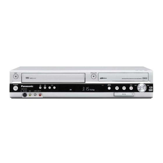
DMR-EZ45VEB 5 LOCATION OF CONTROLS AND COMPONENTS Remote Control DVD/VHS Stand-by/on switch Turn the television set on and off. DVD/VHS Press to switch the unit from on to stand-by mode or vice versa. In stand-by mode, the unit is still consuming Select the AV input on the television set. -
Page 11: Operating Intructions
DMR-EZ45VEB 6 OPERATING INTRUCTIONS 6.1. (DVD) TAKING OUT THE DISC FROM RAM-DRIVE UNIT WHEN THE DISC CANNOT BE EJECTED BY OPEN/CLOSE BUTTON 6.1.1. (DVD) FORCIBLE DISC EJECT 6.1.2. (DVD) WHEN THE FORCIBLE DISC EJECT CAN NOT BE DONE. 6.1.1.1. (DVD) WHEN THE POWER CAN 1. -
Page 12: Vhs) Removing Of Cassette Tape
DMR-EZ45VEB 6.2. (VHS) REMOVING OF 3. Stop unloading just before unloading will be completed. The CASSETTE TAPE tape becomes slack. When the cassette tape could not be removed after an 4. Rotate the S-Reel by a small minus screwdriver to remove electrical malfunction, there are 2 ways to remove a cassette the slack tape. - Page 13 DMR-EZ45VEB 6.2.3. (VHS) TAKE OUT CASSETTE TAPE 6. Attach Loading Motor and tighten the screw. MANUALLY AFTER REMOVING 7. Set the Position Switch to EJECT POSITION certainly and THE MECHANNISM attach the mechanism to chassis. 1. Disconnect the AC plug, and remove the Top Panel, Front Panel and the Mechanism by referring assembling and disassembling description.
-
Page 14: Service Mode
DMR-EZ45VEB 7 SERVICE MODE 7.1. (DVD) SELF-DIAGNOSIS AND SPECIAL MODE SETTING 7.1.1. (DVD) SELF-DIAGNOSIS FUNCTIONS Self-Diagnosis Function provides information for errors to service personnel by “Self-Diagnosis Display” when any error has occurred. U**, H** and F** are stored in memory and held. - Page 15 DMR-EZ45VEB Error Code Diagnosis contents Description Monitor Display Automatic FL display The unit is carrying out its * The unit detected an error while recording No display recovery process (with no or playing with with no disc in the disc disc in the disc tray).
- Page 16 DMR-EZ45VEB Error Code Diagnosis contents Description Monitor Display Automatic FL display Unformatted disc error You have inserted an unformatted DVD- Format: FORMAT RAM or DVD-RW that is unformatted or This disc is not recorded on other equipment. formatted properly. Format the disc in...
- Page 17 DMR-EZ45VEB 7.1.2. SPECIAL MODES SETTING Item FL display Key operation Mode name Description Front Key TEST Mode *All the main unit´s parameters (include Press [VHS to DVD COPYING], tuner) are initialized. [REC] and [OPEN/CLOSE] keys simultaneously for five seconds when power is off.
- Page 18 DMR-EZ45VEB Item FL display Key operation Mode name Description Front Key Aging Contents (Example): Demonstration Ejection of the disc is prohibited. *When lock the tray. When the power is on, press lock/unlock The lock setting is effective until unlocking [STOP] and [POWER] keys the tray and not released by “Main unit...
- Page 19 DMR-EZ45VEB 7.1.3. (DVD) SERVICE MODES Service mode setting: While the power is off, press [STOP], [VHS to DVD COPYING] and [OPEN/CLOSE] simultaneously for five seconds. Item FL display Key operation Mode name Description (Remote controller key) Release Items Item of Service Mode executing is cancelled.
- Page 20 DMR-EZ45VEB Item FL display Key operation Mode name Description (Remote controller key) Magenta Picture Output Magenta picture is output with Component *Initial mode is “Interlace”. Press [1] [2] in service mode. Output from AV Decoder. *Magenta picture (Saturation rate: 100%) *It is enable to switch Interlace/Progressive by “I/P switch: [1] [4]”...
- Page 21 DMR-EZ45VEB Item FL display Key operation Mode name Description (Remote controller key) RAM Drive Last Error RAM Drive error code display. 1. Error Number is displayed for 5 Press [4] [2] in service mode. *For details about the drive error code, refer seconds.
- Page 22 DMR-EZ45VEB Item FL display Key operation Mode name Description (Remote controller key) Front connection Press all front keys and check the Press [5] [4] in service mode. inspection connection between Main P.C.B. and Front key Switches. (1) Each time a key is pressed, segment turned on increases one by one.
- Page 23 DMR-EZ45VEB Item FL display Key operation Mode name Description (Remote controller key) SD card WRITE check Check SD card WRITE function with SD When the WRITE check is OK. Insert a SC card to SD card slot, slot. and press [7] [4] in service mode.
-
Page 24: Vhs) Self-Diagnosis And Special Mode
DMR-EZ45VEB 7.2. (VHS) SELF-DIAGNOSIS AND SPECIAL MODE SETTING 7.2.1. (VHS) SPECIAL MODES SETTING Item FL display Key operation Mode name Description Front Key Tracking Center Tape Tracking is adj usted to center No display. During PLAYBACK, press [VHS CH FIX position. - Page 25 DMR-EZ45VEB Service Mode Contents Contents of Indication on minute Contents of Indication on second Remarks Number Manual mechanism Mechanism position (Real time) Ordering for the Motors Press the following key; operation PLAY key: Loading 0L: EJECT position 0*, 2*: CYL off,...
-
Page 26: Service Fixture And Tools
DMR-EZ45VEB 7.2.3.1.3. CLEAR FOR THE SELF-DIAGNOSIS HISTORY 1. Press STOP and EJECT buttons simultaneously over 5 seconds during turning on Service Information Display mode. 7.2.3.1.4. INDICATION OF THE SELF-DIAGNOSIS HISTORY The self-diagnosis histories can be indicated on the FIP with Service Mode number 3 to 5. -
Page 27: Assembling And Disassembling
DMR-EZ45VEB 9 ASSEMBLING AND DISASSEMBLING 9.1. DISASSEMBLY FLOW CHART The following chart is the procedure for disassembling the casing and inside parts for internal inspection when carrying out the servicing. To assemble the unit, reverse the steps shown in the chart below. -
Page 28: Top Case
DMR-EZ45VEB 9.4. TOP CASE 9.5. FRONT PANEL 1. Remove the 4 screws (A) and 3 screws (B). 1. Remove one screw (A). 2. Slide the Top Case for rear direction slightly, and open the 2. Unlock tab (A) and tab (B) simultaneously. -
Page 29: Front Jack P.c.b. & Fl Drive
DMR-EZ45VEB Note: 9.7. REAR PANEL & FAN MOTOR When attaching Front Panel, in order to hook Cassette 1. Remove 10 Screws (A), Screw (B) Door Opener Lever to Cassette Door, push up cassette and Fan Connector. door in the direction of arrow and insert a front panel. -
Page 30: Vcr Mechanism Unit
DMR-EZ45VEB 9.8.1. CAUTION FOR ATTACHING VCR 9.8. VCR MECHANISM UNIT MECHANISM UNIT 1. Disconnect 3 Connectors (P1531, P2501 and P4002). 1. Because Position SW should be set to "Eject Position", 2. Remove 3 black Screws (A), Screw (B), Screw (C) refer to fig.(A) and set the position switch so that the boss... -
Page 31: Main P.c.b
DMR-EZ45VEB 9.9. MAIN P.C.B. 9.10. TUNER 1. Disconnect 3 Connectors. 1. Remove the solders. 2. Remove 3 Screws and remove Main P.C.B. 2. Pull out the Tuner from Main P.C.B. -
Page 32: Dvd-Ram Drive / Digital P.c.b. Module
DMR-EZ45VEB 9.11. DVD-RAM DRIVE / DIGITAL P.C.B. MODULE CAUTION: The DVD-RAM Drive and the Digital P.C.B. have to be replaced together as one Module. If the Module is changed the DVD-RAM Drive has to be re-aligned because the aligment data for the DVD-RAM Drive is stored in the Digital P.C.B. -
Page 33: Sd/Dv In P.c.b
DMR-EZ45VEB 9.12. SD/DV IN P.C.B. 1. Remove 2 Screws. 2. Pull out the DV IN P.C.B. backwards. CAUTION: When replacing the Module, pay attention to inserting FFC, and be careful to do not touch surface of CSP ICs. If you have touched surface of CSP IC, clean up with alcohol and so on to prevent oxidation. -
Page 34: Power & Digital I/F P.c.b
DMR-EZ45VEB Caution: 9.13. POWER & DIGITAL I/F P.C.B. The earth springs has to contact the Metalchassis. 1. Remove Rear Panel and disconnect 3 Connectors. 2. Remove the 6 Screws. 3. Remove DVD Angle (A) and DVD Angle (B). 4. Remove Power & Digital I/F P.C.B. -
Page 35: Back End P.c.b
DMR-EZ45VEB 9.14. BACK END P.C.B. 1. Pull out the Back End P.C.B. in direction of the arrow. 9.15. HDMI P.C.B. 1. Remove Screw on backside of Rear Panel. 2. Pull out the HDMI P.C.B. in the direction of the arrow. -
Page 36: Measurements And Adjustments
DMR-EZ45VEB 10 MEASUREMENTS AND ADJUSTMENTS 10.1. SERVICE POSITIONS 10.1.1. CHECKING AND REPAIRING OF POWER & DIGITAL I/F P.C.B. CAUTION: Before repairing of Power & Digital I/F P.C.B. read and observe “CAUTION FOR DIVX” (NEW FEATURE) first. 1. Top Case · Remove 4 Screws (A) on side and 3 Screws (B) on rear side. - Page 37 DMR-EZ45VEB 10.1.2. CHECKING AND REPAIRING OF MAIN P.C.B. 1. Top Case · Remove 4 Screws (A) on side and 3 Screws (B) on rear side and remove the Top Case. 2. Front Panel · Remove on Screw (A) on center.
- Page 38 DMR-EZ45VEB 10.1.3. CHECKING AND REPLACING OF DVD-RAM DRIVE / DIGITAL P.C.B. MODULE 1. Top Case · Remove 4 Screws (A) on side and 3 Screws (B) on rear side. · Remove Top Case. 2. Front Panel · Remove one Screws (A) on center.
-
Page 39: Caution For Replacing Parts
DMR-EZ45VEB 10.2. CAUTION FOR REPLACING PARTS 10.2.1. NOTICE AFTER REPLACING DVD-RAM/DIGITAL P.C.B. MODULE TM AV1 is displayed after replacing DVD-RAM/Digital P.C.B. Module. Power-off and start-up again. 10.2.2. NOTICE FOR REPLACING PARTS OF VHS MECHANISM 10.2.2.1. REGARDING CHANGE OF PARTS OF VHS MECHANISM The following parts are not compatible with past R4 Mechanism. - Page 40 DMR-EZ45VEB 10.2.2.3. ITEMS THAT SHOULD BE DONE AFTER REPLACING PARTS * Note 1: Resetting object Condition of power Short Terminal IC6001 POWER ON TL6004 (Reset_L) and TL6002 (GND) IC9704 POWER ON IC9706-4 (Reset_L) and GND...
- Page 41 DMR-EZ45VEB * Note 2: PG Shifter Automatic Adjustment Procedure PROCEDURE F.I.P. DISPLAY Turn on the Service Mode 1. Set Drive Select to VHS and press the [STOP] and [EJECT] key simultaneously for more than 3 seconds. Activate the Service Mode 2 (Auto tracking will be turned off).
- Page 42 DMR-EZ45VEB Alignment Tape VFM8125H3F Test Point of Playback Envelope TW3001 (or TW4502) LINEARITY ADJUSTMENT 1. After turning off the Auto tracking, playback the alignment Tape and press [VHS CH UP] and [VHS CH DOWN] keys simultaneously to adjust the tracking to FIX value.
- Page 43 DMR-EZ45VEB...
-
Page 44: After Making Repairs
Perform auto recording and playback for one minute using No abnormality should be seen in the picture, sound or operation. the RAM disc. *Panasonic DVD-RAM disc should be used when recording and playback. If a problem is caused by a VCD, DVD-R, DVD-Video, No abnormality should be seen in the picture, sound or operation. -
Page 45: Miscellaneous
DMR-EZ45VEB 11 MISCELLANEOUS 11.1. ABBREVIATIONS INITIAL/LOGO ABBREVIATIONS COMMON GROUNDING (EARTH) 11.1.1. DVD HA0~UP HOST ADDRESS HD0~UP HOST DATA HINT HOST INTERRUPT INITIAL/LOGO ABBREVIATIONS HRXW HOST READ/WRITE A0~UP ADDRESS IECOUT IEC958 FORMAT DATA OUTPUT ACLK AUDIO CLOCK IPFRAG INTERPOLATION FLAG AD0~UP... - Page 46 DMR-EZ45VEB INITIAL/LOGO ABBREVIATIONS INITIAL/LOGO ABBREVIATIONS SBI0, 1 SERIAL DATA INPUT VBLANK V BLANKING SBO0 SERIAL DATA OUTPUT COLLECTOR POWER SUPPLY SBT0, 1 SERIAL CLOCK VOLTAGE SERIAL DATA CLOCK VCDCONT VIDEO CD CONTROL (TRACKING SCKR AUDIO SERIAL CLOCK RECEIVER BALANCE) SERIAL CLOCK...
- Page 47 DMR-EZ45VEB 11.1.2. VHS 3-1. ABBREVIATIONS 4.43 NTSC L 443NT [L] BILINGUAL BILINGUAL L A. COMP BIL [L] AUDIO COMPONENT SIGNAL BILINGUAL H BIL. [H] A. COMPO AUDIO COMPONENT SIGNAL BILINGUAL L AUDIO DUBBING PAUSE L BIL/M1 [L] A. D.P [L]...
- Page 48 DMR-EZ45VEB CYL GND CYLINDER GND FULL. E. 12V FULL ERASE 12V DELAIED FM RECORDING H D.F.M. REC [H] GND [A] GND (ANALOG) DELAIED FM RECORDING L D. FM REC [L] GND [TU] GND (TUNER) D. GND GND/NON SW 12V DIGITAL GND GND/N.
- Page 49 DMR-EZ45VEB POWER OFF H LINE IN [R] LINE INPUT (R) P-OFF [H] POWER OFF L LINE OUT [L] LINE OUTPUT (L) P-OFF [L] LINE OUT [R] LINE OUTPUT (R) P. FAIL POWER FAILURE DETECT LP H POWER OFF H LP [H] P.
- Page 50 DMR-EZ45VEB SYSTEM CONTROL 5V RF OUT RF OUTPUT SYSCON 5V SYSTEM SW RF Y RF LUMINANCE SIGNAL SYSTEM TAKE-UP PHOTO TRANSISTOR RF. Y. IN RF LUMINANCE SIGNAL INPUT T-PHOTO TAKE-UP REEL PULSE RF. Y. OUT RF LUMINANCE SIGNAL OUTPUT T-RL. PLS TIMER BUS CLOCK ROTAR.
-
Page 51: Block Diagram
DMR-EZ45VEB 12 BLOCK DIAGRAM 12.1. POWER SUPPLY BLOCK DIAGRAM COLD D1102 D1103 D1101, L1101 D1104 L1102 D1105 T1101 SW TRANSFORMATOR AC-Socket RECTIFIER P1101 250V T2AL F1101 C1103 D1201 X_SW17V SURGE ABSORBER D1202 D1203 Q1202 IC1201 X_SW5R8V IC1101 SW IC Q1101... -
Page 52: System Control, Servo & Timer Block Diagram
DMR-EZ45VEB 12.2. SYSTEM CONTROL, SERVO & TIMER BLOCK DIAGRAM IC0201 (CAPSTAN MOTOR DRIVE) IC6001 (SYSTEM CONTROL/SERVO/TIMER) X SW +12V P0201 P2571 TL2502 CAPSTAN CAP TL MOTOR COILS P0201 P2571 MOTOR DIFFERENTIAL TORQUE CURRENT LIMIT DRIVE AMPLIFIRE CONTROL P0201 P2571 CAP ET... -
Page 53: Audio Block Diagram
DMR-EZ45VEB 12.3. AUDIO BLOCK DIAGRAM :REC SIGNAL :PB SIGNAL JK9301 REAR JACK Q9305 P9703 MIX_LOUT_DM LINE OUT Q9303 Q9304 FROM DIGITAL P.C.B. LINE OUT P9703 MIX_ROUT_DM Q9302 FROM XT_MUTE DIGITAL IC9704 INTERFACE IC3901 (SA1R) JK3901 21 PIN JACK P9103 P6003 DAC Rch BUFF. -
Page 54: Video Block Diagram
DMR-EZ45VEB 12.4. VIDEO BLOCK DIAGRAM REC SIGNAL PB SIGNAL IC3901 MAIN P.C.B. ENC C IN P9703 P9103 P6003 C OUT DM ENC Y IN P9703 P9103 P6003 Y OUT DM ENC R/R-Y IN FROM P9703 P9103 P6003 RPROUT DM DIGITAL P.C.B. - Page 55 DMR-EZ45VEB REC SIGNAL PB SIGNAL IC3001 (AUDIO/VIDEO SIGNAL PROCESSOR) FIXED TO INT IN THES MODELS BY PIN53 2MHz IC3905 SQUELCH SVHS IC3901 -6dB -4dB FROM SVHS P9703 P9103 P6003 DIGITAL CLEAR SQUELCH V-AMP -10dB SYNC C_IN VIDEO FEED BACK NTSC/PAL...
-
Page 56: Digital I/F P.c.b. Block Diagram
DMR-EZ45VEB 12.5. DIGITAL I/F P.C.B. BLOCK DIAGRAM FL DRIVE IC7501 DP7501 IC 9704 (LPF) FL00 P1− P16 PS9702 PP7502 FL RESET RESET PS9702 PP7502 FL_CLK PS9702 PP7502 FL_RXD 10 SDAT A FL_TXD FL21 2G− 7G 32KHZ IN X9702 32KHZ OUT... -
Page 57: Hdmi Block Diagram
DMR-EZ45VEB 12.6. HDMI BLOCK DIAGRAM IC56101 IC56103 IC56102 (HDMI TRANSMITTER) P55002 FP56101 P55002 FP56101 P55002 FP56101 P55002 FP56101 Convertor Converter Video P55002 FP56101 Color Space P55002 FP56101 P55002 FP56101 HDMI CONNECTOR P55002 FP56101 TX2P P56102 L56101 TX2M P56102 TX1P P56102... - Page 58 DMR-EZ45VEB...
-
Page 59: Schematic Diagram
DMR-EZ45VEB 13 SCHEMATIC DIAGRAM 13.1. INTERCONNECTION DIAGRAM P55002 R656_OUT0 P56102 R656_OUT1 R656_OUT3 R656_OUT2 R656_OUT4 R656_OUT5 R656_OUT7 R656_OUT6 HDMI P.C.B. R656_CLK HDMI_27CLK HDMI_1_IRQ FP56101 I2C_SCL1 I2C_SDA1 HDMI_2_IRQ RESET DMIX ADACOUT2 ADACOUT1 FP50002 ADACOUT0 DAC_LRCK P56101 DAC_BCK DAC_MCK IECOUT 63 64 ACT_FOC1-... -
Page 60: Power Supply
DMR-EZ45VEB 13.2. POWER SUPPLY TL1209 HDD_PFAIL_L HDD_PFAIL_L TL1208 P_SAVE_L C1111 LB1105 P_SAVE_L T1101 D1201 LB1201 TL1201 X_SW17V L1202 X_SW17V D1202 F1101 DG1110 DG1112 FH1101 FH1102 D1102 DISCHARGE GAP C1102 DISCHARGE GAP K1205 R1201 K1201 C1202 C1201 R1202 25V470 R1101 250V T2AL... -
Page 61: Digital I/F
DMR-EZ45VEB 13.3. DIGITAL I/F C9311 16V47 3.3V-Reset R9313 R9711 R9712 R9334 470K R9312 R9311 C9318 LB9702 Q9704 R9316 R9736 IC9702 Q9703 Q9702 QR9304 FAN_PWM_OUT R9705 C9315 R9704 Q9706 SYS_P_FAIL[H] R9710 1000P R9709 C9715 4700 0.01 C9701 QR9701 R9301 FAN_DC_OUT R9780... -
Page 62: Io / Tuner
DMR-EZ45VEB 13.4. IO / TUNER P7801 P7802 P6004 *(DVB) * (DVB) * (DVB) C4101 470P C4107 470P K7810 LB7801 C4102 470P C4108 470P K7811 * (DVB) R4101 R4102 R4103 K7809 COMBO ANALOG * (ANT_P) (5V<=ANT_PON) R4104 BB: +5V ANT +5V Booster (5V<=NSW) -
Page 63: Syscon / Servo / Timer Main
DMR-EZ45VEB 13.5. SYSCON / SERVO / TIMER MAIN P6002 P6001 P6003 MIX_R_MUTE MIX_L_MUTE AU_GND QR7901 C7901 L7901 AADC_L 35V220 IP7901 AADC_R R/PR_OUT_DM R7901 G/PY_OUT_DM B/PB_OUT_DM 5600 Q7901 X_SW_5R8V X_SW_5R8V REG_12V C7902 R7903 IP4901 $ 330 D7902 R1511 TL24 D7901 C7903... -
Page 64: Video
DMR-EZ45VEB 13.6. VIDEO R2099 R4019 6800 C2099 680P Q4002 QR4004 R4018 Q4001 K4003 NA_GND LB4203 HA_GND C4007 C4016 2200P 6V22 QR4003 C4008 1800P R4006 R4007 C5006 100K 3300 6V47 L5001 C4005 6V100 C5007 C4009 C3034 6V22 50V1 R4014 R4001 R4002... -
Page 65: Audio Nicam
DMR-EZ45VEB 13.7. AUDIO NICAM TL4501 TW4501 FM-MIX OUT C4517 R4532 C4518 0.22 L4501 L7302 PB-FM ENV (only ES35) TW4502 D4501 C7315 C4505 6V33 (only ES35) C7309 * R4516 C4519 R4517 C7310 * 0.015 L7301 R4515 C4546 R7302 * R4522 (only ES35) -
Page 66: Front Jack
DMR-EZ45VEB 13.8. FRONT JACK R7801 R7802 3300 S7801 S7802 S7803 POWER CH UP PP4801 CPN_Y_IN2 CPN_C_IN2 L2_R_IN L2SW L2_L_IN KEY2 L2_V_IN2 R7803 R7804 3300 KEY_GND KEY1 K7801 S7805 S7806 S7804 EJECT CH DOWN K7802 JK4802 JK4801 R4803 R4801 R4802 C4801 0.01... -
Page 67: Fl Drive
DMR-EZ45VEB 13.9. FL DRIVE R7510 5600 R7507 1800 S7501 S7504 S7507 R7502 R7503 R7504 R7501 * $ PLAY R7508 1800 S7502 S7505 DUB_LED STOP QR7501 * $ QR7502 QR7503 QR7504 R7509 1800 S7503 S7506 SELECT OPEN/CLOSE C7502 C7501 C7507 R7525... -
Page 68: Sd/Dv In
DMR-EZ45VEB 13.10. SD/DV IN SDAT2 R66806 SDAT3 R66805 SCMD R66804 P66802 SDAT0 R66802 CKF20 SDAT1 CKF19 DAT1 SDAT1 R66801 SDAT0 CKF18 DAT0 G_SCLK_B R66803 P66801 CKF17 G_SCLK_B CKF16 CKE9 R66809 SDAT2 9 DAT2 CKF15 SCMD CKE1 CKF14 SDAT3 R66810 SDAT3... -
Page 69: Hdmi
DMR-EZ45VEB 13.11. HDMI IC56101 FL56101 LB56102 C56101 R56139 R56151 R656_0 G_R656_CK_C R56155 R56152 LB56103 R656_6 R656_1 FL56103 116 115 111 110 106 105 102 101 96 95 92 91 R56156 R56153 R656_5 R656_2 R56140 R56144 PCLKOUT [124]DO29 [82]AVSS TX2M L56101... - Page 70 DMR-EZ45VEB...
-
Page 71: Printed Circuit Board
DMR-EZ45VEB 14 PRINTED CIRCUIT BOARD 14.1. POWER & DIGITAL I/F P.C.B. (COMPONENT SIDE) K9105 K9102 W124 C9768 ZJ9107 ZJ9103 L1101 L1102 C9785 D9107 C1113 C9117 C1101 P1101 L1213 W199 PS9701 LB1105 R1101 R1102 FH1101 FH1102 D1101 W201 F1101 C1111 R1103... -
Page 72: Power & Digital I/F P.c.b. (Solder Side)
DMR-EZ45VEB 14.2. POWER & DIGITAL I/F P.C.B. (SOLDER SIDE) ZJ9103 ZJ9107 K9102 K9105 C9768 C9785 D9107 C9117 C1113 C1102 K9702 L1102 L1101 R9840 R9836 C1101 C9135 K1202 P1101 L9106 R9839 D1103 D1102 L1213 R9809 R9805 R9807 TL1210 D9104 C9156 LB1105... -
Page 73: Main P.c.b. (Component Side)
DMR-EZ45VEB 14.3. MAIN P.C.B. (COMPONENT SIDE) ADRESS INFORMATION IC1501 T4001 IC1502 T7901 T PHOTO P1531 TU7801 P6004 P6003 P6002 P6001 R2503 P2501 Q1501 W396 P2571 TW2001 D7803 W314 P4001 TW2002 JK4903 W385 W592 D2502 W395 P4002 TW3001 D7805 P5001 TW4501... -
Page 74: Main P.c.b. (Solder Side)
DMR-EZ45VEB 14.4. MAIN P.C.B. (SOLDER SIDE) ADRESS INFORMATION IC1501 QR3001 LB7401 IC1502 QR3002 Q1501 P6001 P6004 P6002 P6003 IC2501 QR3005 R2503 W529 C6017 D7803 QR4901 IC3001 QR4003 W410 W408 W529 W407 QR4915 IC3002 QR4004 R7845 D2502 IC3901 QR4005 QR4902 TL6002... -
Page 75: Front Jack P.c.b
DMR-EZ45VEB 14.5. FRONT JACK P.C.B. FRONT JACK COMPONENT SIDE FRONT JACK SOLDER SIDE EJECT EJECT S7804 S7804 R7802 R7804 K7801 DOWN DOWN S7803 S7802 S7805 S7802 S7806 S7803 S7806 S7805 K7802 POWER POWER R7801 S7801 S7801 W4818 W4812 W4813 W4807... -
Page 76: Fl Drive P.c.b
DMR-EZ45VEB 14.6. FL DRIVE P.C.B. FL DRIVE COMPONENT SIDE S7506 OPEN/CLOSE C7502 L7501 DUB_LED D7502 STOP PLAY D7501 S7501 S7504 S7507 S7502 S7505 D7504 S7503 IC7502 D7503 W7508 DP7501 PP7503 W7503 PP7502 PP7501 FL DRIVE SOLDER SIDE OPEN/CLOSE S7506 QR7502... -
Page 77: Sd/Dv In P.c.b
DMR-EZ45VEB 14.7. SD/DV IN P.C.B. COMPONENT SIDE PP66802 PP66803 SOLDER SIDE P66803 DMR-EZ45VEB SD/DV IN PCB COMPONENT SIDE / SOLDER SIDE... -
Page 78: Hdmi P.c.b
DMR-EZ45VEB 14.8. HDMI P.C.B. P56102 CKA20 R56137 R56138 VA56111 LB56112 CKC2 CKC1 R56128 R56129 VA56113 VA56110 VA56106 VA56102 VA56112 VA56108 VA56104 VA56101 FL56110 R56131 C56128 LB56116 R56125 R56126 R56160 C56125 CKC4 CKC5 CKC7 C56127 C56122 R56123 C56119 R56127 C56121 C56120 C56118... -
Page 79: Appendix For Schematic Diagram
DMR-EZ45VEB 15 APPENDIX FOR SCHEMATIC DIAGRAM 15.1. VOLTAGE AND WAVEFORM CHART NOTE: · Indicated voltage values are the standard values for the unit measured by the DC electronic circuit tester (high-impedance) with the chassis taken as standard. Therefore, there may exist some errors in the voltage values, depending on the internal impedance of the DC circuit tester. - Page 80 DMR-EZ45VEB 15.1.2. VOLTAGE CHART (IC3001-IC9706, Q1201-Q6801, QR1202-QR7901, P6001-P9703) Ref.No. IC3001 Mode Stop 0,00 0,00 0,06 5,12 2,09 2,59 2,83 1,94 1,86 2,03 Play 0,00 0,00 0,06 5,12 2,09 2,59 2,83 1,94 1,86 2,03 Rec. 0,00 0,00 0,06 5,12 2,09 2,59...
- Page 81 DMR-EZ45VEB Ref.No. IC3002 Mode Stop 5,14 0,00 1,28 0,00 4,87 0,00 0,00 5,65 Play 5,14 0,00 1,28 0,00 4,87 0,00 0,00 5,65 Rec. 5,14 0,00 1,28 0,00 4,87 0,00 0,00 5,65 Ref.No. IC3901 Mode Stop 2,01 2,51 1,51 0,00 1,57...
- Page 82 DMR-EZ45VEB Ref.No. IC3901 Mode Stop 2,02 3,19 2,09 4,92 2,01 0,00 2,04 0,00 2,01 2,45 Play 2,02 3,19 2,09 4,92 2,01 0,00 2,04 0,00 2,01 2,45 Rec. 2,02 3,19 2,09 4,92 2,01 0,00 2,04 0,00 2,01 2,45 Ref.No. IC3905 Mode...
- Page 83 DMR-EZ45VEB Ref.No IC6001 Mode Stop 0,00 0,00 0,00 5,03 3,91 0,00 0,00 0,00 0,00 0,03 Play 0,00 0,00 0,00 5,03 3,91 0,00 0,00 0,00 0,00 0,00 Rec. 0,00 0,00 0,00 5,03 3,91 0,00 0,00 0,00 0,00 0,03 Ref.No. IC6001 Mode...
- Page 84 DMR-EZ45VEB Ref.No. IC7301 Mode Stop 2,42 2,43 2,43 0,00 0,00 2,43 0,00 2,42 0,00 2,43 Play 2,42 2,43 2,43 0,00 0,00 2,43 0,00 2,42 0,00 2,43 Rec. 2,42 2,43 2,43 0,00 0,00 2,43 0,00 2,42 0,00 2,43 Ref.No IC7301 Mode...
- Page 85 DMR-EZ45VEB Ref.No. IC9301 Mode Stop 1,27 0,00 4,78 5,68 0,00 5,00 Play 1,27 0,00 4,78 5,68 0,00 5,00 Rec. 1,23 0,00 4,77 5,68 0,00 5,00 Ref.No. IC9302 Mode Stop 4,78 3,33 3,33 0,00 3,33 3,33 4,74 10,54 Play 4,78 3,33...
- Page 86 DMR-EZ45VEB Ref.No. IC9704 Mode Stop 4,83 0,01 0,00 0,01 0,00 0,00 0,01 0,00 0,01 5,02 Play 4,83 0,01 0,00 0,01 0,00 0,00 0,01 0,00 0,01 5,03 Rec. 4,83 0,01 0,00 0,01 0,00 0,00 0,01 0,00 0,01 5,02 Ref.No. IC9704 Mode...
- Page 87 DMR-EZ45VEB Ref.No. Q6404 Q9106 Q9701 Mode Stop 0,00 0,02 5,04 3,29 3,94 5,59 2,73 2,13 0,00 Play 0,00 0,02 5,04 3,29 3,94 5,59 2,73 2,13 0,00 Rec. 0,00 0,02 5,03 3,29 3,94 5,59 2,56 1,91 0,00 Ref.No. Q9702 Q9703 Q9705...
- Page 88 DMR-EZ45VEB Ref.No. QR4004 QR4005 QR4501 Mode Stop 5,13 0,03 5,04 0,00 0,01 5,65 0,00 4,87 0,02 Play 5,13 0,03 5,04 0,00 0,01 5,65 0,00 4,87 0,02 Rec. 5,13 0,03 5,04 0,00 0,01 5,65 0,00 4,87 0,02 Ref.No. QR4901 QR4902 QR4903...
- Page 89 DMR-EZ45VEB Ref.No. P6003 Mode Stop 2,08 1,41 0,00 0,84 0,62 0,87 0,00 0,85 0,57 5,68 Play 2,08 1,41 0,00 0,84 0,62 0,87 0,00 0,85 0,57 5,68 Rec. 2,08 1,41 0,00 0,84 0,62 0,87 0,00 0,85 0,57 5,68 Ref.No P6003 Mode...
-
Page 90: Waveform Chart
DMR-EZ45VEB 15.1.3. WAVEFORM CHART NOTE: The waveforms are measured with PAL colour bar signal. T1101-5 STOP T1101-6 STOP IC6001-13 PAUSE IC6001-18 REC IC6001-19 REC 50Vp-p (5µsec.div) 0.2Vp-p (5µsec.div) 5.0Vp-p (10msec.div.) 5.0Vp-p (10msec.div.) 5.0Vp-p (10msec.div.) IC6001-48 REC IC6001-52 REC IC6001-68,69 REC... -
Page 91: Exploded Views
DMR-EZ45VEB 16 EXPLODED VIEWS 16.1. MECHANISM & CASING PARTS... -
Page 92: Front Panel Parts
DMR-EZ45VEB 16.2. FRONT PANEL PARTS... -
Page 93: Vhs Mechanism Parts
DMR-EZ45VEB 16.3. VHS MECHANISM PARTS... -
Page 94: Packing & Accessories
DMR-EZ45VEB 16.4. PACKING & ACCESSORIES... -
Page 95: Replacement Parts List
DMR-EZ45VEB 17 REPLACEMENT PARTS LIST Notes: Ref. Part No. Part Name & Remarks Description *Important safety notice: RMCD0002 EARTH SPRING (FRONT) 1 Components identified mark have special RYP1336-S FRONT PANEL UNIT 37-1 RKF0757A-S BLINDER PANEL characteristics important for safety. 37-2... -
Page 96: Packing & Accessories Parts
DMR-EZ45VEB Ref. Part No. Part Name & Remarks Ref. Part No. Part Name & Remarks Description Description VXL3160 MAIN SHAFT C1220 F1H1C104A042 CHIP CAPACITOR VXA8323 SECTOR GEAR C1222 F1H1C224A074 CHIP CAPACITOR VML3706-3 OPENER LEVER C1223 F2A1A681A540 ALU ELEC CAPACITOR VHD1044-1... - Page 97 DMR-EZ45VEB Ref. Part No. Part Name & Remarks Ref. Part No. Part Name & Remarks Description Description C3034 ECEA1HKA010B ALU ELEC CAPACITOR C4021 ECJ1VC1H471J CHIP CAPACITOR C3036 ECEA1HKA4R7B ALU ELEC CAPACITOR C4022 ECA0JM101B ALU ELEC CAPACITOR C3037 ECEA1HKAR47B ALU ELEC CAPACITOR...
- Page 98 DMR-EZ45VEB Ref. Part No. Part Name & Remarks Ref. Part No. Part Name & Remarks Description Description C4944 ECEA1CKA470B ALU ELEC CAPACITOR C66801 F1H1H1030006 CHIP CAPACITOR C4945 F2A1C221A019 ALU ELEC CAPACITOR C66802 F1H1A225A051 CHIP CAPACITOR C5001 F1H1H1030006 CHIP CAPACITOR C7301 F1H1H1030007...
- Page 99 DMR-EZ45VEB Ref. Part No. Part Name & Remarks Ref. Part No. Part Name & Remarks Description Description C9006 ECJ1VC1H020C CHIP CAPACITOR C9705 F1H1H1030007 CHIP CAPACITOR C9007 ECJ2FB1A225K CHIP CAPACITOR C9706 ECEA0JKA101B ALU ELEC CAPACITOR C9008 F1H1C104A042 CHIP CAPACITOR C9707 F1H1E104A030...
- Page 100 DMR-EZ45VEB Ref. Part No. Part Name & Remarks Ref. Part No. Part Name & Remarks Description Description C9822 ECJ1VB1C105K CHIP CAPACITOR D9104 MAZ40390HF DIODE C9823 ECJ1VB1C105K CHIP CAPACITOR D9105 B0AACK000004 SWITCHING DIODE C9824 ECJ1VB1C105K CHIP CAPACITOR D9106 B0JACE000001 DIODE C9825 ECJ1VB1C105K...
- Page 101 DMR-EZ45VEB Ref. Part No. Part Name & Remarks Ref. Part No. Part Name & Remarks Description Description JK4802 K1CB104A0017 CONNECTOR LB1105 EXCELDR35V BEAD CORES JK4901 K2HA304B0007 CONNECTOR LB1203 ERJ6GEY0R00Z CHIP RESISTOR JK4902 K1CB105B0041 CONNECTOR LB1204 ERJ6GEY0R00Z CHIP RESISTOR JK4903 K2HA1YYB0002...
- Page 102 DMR-EZ45VEB Ref. Part No. Part Name & Remarks Ref. Part No. Part Name & Remarks Description Description P6001 K1KB15AA0032 CONNECTOR 15POL. QR4005 B1GBCFNN0009 TRANSISTOR P6002 K1KB19AA0032 CONNECTOR 19POL. QR4501 B1GBCFJJ0007 TRANSISTOR P6003 K1KB19AA0032 CONNECTOR 19POL. QR4901 B1GBCFNN0009 TRANSISTOR P6004 K1KB09A00047...
- Page 103 DMR-EZ45VEB Ref. Part No. Part Name & Remarks Ref. Part No. Part Name & Remarks Description Description R2501 ERJ6GEYJ1R2V CHIP RESISTOR R4507 D0GB472JA057 CHIP RESISTOR R2502 ERJ6GEYJ1R5V CHIP RESISTOR R4508 D0GB912JA057 CHIP RESISTOR R2503 ERDS2TJ103T CARBON RESISTOR R4509 D0GB472JA057 CHIP RESISTOR...
- Page 104 DMR-EZ45VEB Ref. Part No. Part Name & Remarks Ref. Part No. Part Name & Remarks Description Description R56121 ERJ2GEJ151X RESISTOR R6201 D0GB103JA057 CHIP RESISTOR R56122 ERJ2GEJ151X RESISTOR R6309 D0GB272JA057 CHIP RESISTOR R56123 ERJ2GEJ511X RESISTOR R6401 D0GB221JA057 CHIP RESISTOR R56124 ERJ2GEJ103X...
- Page 105 DMR-EZ45VEB Ref. Part No. Part Name & Remarks Ref. Part No. Part Name & Remarks Description Description R7901 D0GB562JA057 CHIP RESISTOR R9254 D0GB103JA057 CHIP RESISTOR R7902 D0GB470JA057 CHIP RESISTOR R9271 D0GB103JA057 CHIP RESISTOR R7904 ERDS2TJ271T CARBON RESISTOR R9272 D0GB103JA057 CHIP RESISTOR...
- Page 106 DMR-EZ45VEB Ref. Part No. Part Name & Remarks Ref. Part No. Part Name & Remarks Description Description R9726 D0GB101JA057 CHIP RESISTOR R9815 D0GB101JA057 CHIP RESISTOR R9730 D0GB101JA057 CHIP RESISTOR R9816 D0GB101JA057 CHIP RESISTOR R9731 D0GB103JA057 CHIP RESISTOR R9824 D0GB101JA057 CHIP RESISTOR...
- Page 107 DMR-EZ45VEB Ref. Part No. Part Name & Remarks Ref. Part No. Part Name & Remarks Description Description W128 D0YBR0000020 CHIP RESISTOR ERJ6GEY0R00Z CHIP RESISTOR W129 D0YBR0000020 CHIP RESISTOR W512 D0YBR0000020 CHIP RESISTOR W130 D0YBR0000020 CHIP RESISTOR W514 D0YBR0000020 CHIP RESISTOR...
-
Page 108: Service Fixture And Tools
DMR-EZ45VEB 17.5. SERVICE FIXTURE AND TOOLS Ref. Part No. Part Name & Description Remarks RFKZ03D01K Lead Free Solder (0.3 mm / (SPC) 100 g Reel) RFKZ06D01K Lead Free Solder (0.6 mm / (SPC) 100 g Reel) RFKZ010D01 Lead Free Solder (1.0 mm /...