Motorola DCT700 Installation Manual
Digital consumer terminal
Hide thumbs
Also See for DCT700:
- User manual (37 pages) ,
- Specifications (2 pages) ,
- Installation instructions (2 pages)
Table of Contents
Advertisement
Advertisement
Table of Contents

Related Manuals for Motorola DCT700


Summary of Contents for Motorola DCT700
- Page 1 Installation Manual DCT700 Digital Consumer Terminal...
- Page 2 Declaration of Conformity: According to 47 CFR, Parts 2 and 15 for Class B Personal Computers and Peripherals; and/or CPU Boards and Power Supplies used with Class B Personal Computers, Motorola, Inc., 6450 Sequence Drive, San Diego, CA 92121, 1-800-225-9446, declares under sole responsibility that the product identifies with 47 CFR Part 2 and 15 of the FCC Rules as a Class B digital device.
- Page 3 Motorola, Inc. Motorola reserves the right to revise this publication and to make changes in content from time to time without obligation on the part of Motorola to provide notification of such revision or change. Motorola provides this guide without warranty of any kind, either implied or expressed, including, but not limited to, the implied warranties of merchantability and fitness for a particular purpose.
-
Page 4: Table Of Contents
Installing Batteries in the Remote Control........................2-4 Section 3 Installation Before You Begin..................................3-1 Installing the DCT700 ................................3-1 Standard Cabling Diagram ..............................3-2 Standard VCR Cabling Diagram ............................. 3-3 Composite Baseband Cabling Diagrams ..........................3-4 Stereo Cabling Diagrams (Baseband)............................ 3-6 Operational Check.................................. - Page 5 17 In-Band Program Map Table (PMT)..........................B-19 d 18: Task Status ................................. B-19 d 19: USB Diagnostics ................................. B-20 d 20 In-Band Multicast Address Filter ..........................B-20 d 21: Keyboard / LED Diagnostics............................B-20 Abbreviations and Acronyms DCT700 Installation Manual...
- Page 6 Figure 2-3 Motorola DRC450 Universal Remote Control....................... 2-2 Figure 2-4 Back view of DRC450 remote control ........................2-4 Figure 3-1 Connecting the DCT700 to a TV using RF connectors ..................3-2 Figure 3-2 Standard VCR cabling ............................3-3 Figure 3-3 Standard baseband cabling ..........................3-4 Figure 3-4 Baseband audio and video connections to a VCR and TV ..................
-
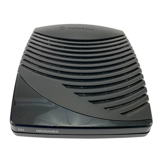
Page 7: Figure 1-1 Dct700 Set-Top Front And Rear Views
Section 1 Introduction The Motorola DCT700 is an interactive digital consumer terminal that enables cable operators to cost-effectively deploy an all-digital network. The DCT700: Supports services such as an electronic program guide (EPG), impulse pay-per view (IPPV), and video on demand (VOD) -
Page 8: Introduction
The Abbreviations and Acronyms list contains the full spelling of the short forms used in this manual. Acronyms Related Documentation Although the DCT700 User Guide may be useful, it is not necessary to install or operate the DCT700 if you have this manual. DCT700 Installation Manual... -
Page 9: Document Conventions
Introduction Document Conventions Before you begin working with this manual and using the DCT700, familiarize yourself with the stylistic conventions used in this manual: Denotes silk screening on the equipment, typically representing front- and rear-panel SMALL CAPS controls, input/output (I/O) connections, and LEDs... -
Page 10: Overview
Function Left and right audio RCA jacks used for stereo audio output. RCA jack used to connect the DCT700 to a composite (baseband) video TV or a monitor; in some configurations this jack connects to a VCR. F-type connector used for DCT700 input from the connector. -
Page 11: Remote Control
Overview Remote Control A remote control is required to operate the DCT700. We recommend the Motorola DRC450 Universal Remote Control: Figure 2-3 Motorola DRC450 Universal Remote Control VCR/DVD CABLE AUDIO HELP POWER PAGE PAGE LOCK EXIT INFO MENU VOLUME LAST... -
Page 12: Table 2-2 Drc450 Remote Control Keys
Recalls the last channel or goes back one screen in the menu. CHANNEL + or - Changes the channels by moving up or down. FAVORITE Displays preset favorite cable channels. ENTER/MUSIC Displays digital music channel menus. On some TV models, press to enter channels. DCT700 Installation Manual... -
Page 13: Installing Batteries In The Remote Control
NOTE! Use and dispose of batteries in accordance with all applicable laws, rules and regulations. Motorola will not be liable to anyone for the user's failure to use and/or dispose of batteries in the proper manner and in accordance with such laws, rules and regulations, or for any defect contained in batteries that may cause injury damage to persons or property. -
Page 14: Installation
Download configuration information and software Run operational check and diagnostics This section also includes the procedure for performing a cold initialization of the DCT700. Before You Begin Before you begin, review the installation instructions, gather the required items, and complete... -
Page 15: Standard Cabling Diagram
Installation Standard Cabling Diagram The DCT700 outputs on either channel 3 or 4 depending on the configuration message from the addressable controller. Figure 3-1 Connecting the DCT700 to a TV using RF connectors From cable outlet DCT700 TV/VCR +12V RF IN... -
Page 16: Standard Vcr Cabling Diagram
VIDEO OUT S-VIDEO OUT S-VIDEO OUT The remodulated channel, 3 or 4, does not carry stereo for digital channels. To receive stereo, connect the DCT700 using RCA baseband connectors. These connections are illustrated later in this section. DCT700 Installation Manual... -
Page 17: Composite Baseband Cabling Diagrams
Installation Composite Baseband Cabling Diagrams Connecting the DCT700 using the baseband RCA type outputs enables the subscriber to experience stereo and Dolby Surround sound when available on digital channels. Figure 3-3 illustrates the standard baseband audio and video outputs of the DCT700:... -
Page 18: Figure 3-4 Baseband Audio And Video Connections To A Vcr And Tv
Baseband audio and video connections to a VCR and TV DCT700 TV/VCR +12V RF IN AUDIO VIDEO AUDIO VIDEO S-VIDEO CABLE IN AUDIO VIDEO S-VIDEO CABLE OUT AUDIO VIDEO IN S-VIDEO IN AUDIO CABLE IN VIDEO OUT S-VIDEO OUT DCT700 Installation Manual... -
Page 19: Stereo Cabling Diagrams (Baseband)
Stereo Cabling Diagrams (Baseband) This audio configuration does not provide for a TV playing through the stereo. Figure 3-5 illustrates how to connect the DCT700 to a stereo using the audio connectors on the VCR: Figure 3-5 Audio on the VCR... - Page 20 Installation This audio configuration enables the TV to play through the stereo. Figure 3-6 shows how to connect the DCT700 to a stereo using the audio loop-through connectors on the VCR and the audio output ports on the TV monitor:...
-
Page 21: Operational Check
If the set-top does not operate properly, refer to Section 4, “Troubleshooting.” Selecting the OOB Frequency Use the Motorola universal remote control to operate the DCT700. To select the OOB frequency: From the O2 OOB STATUS diagnostic, press the MENU button to enter the frequency selection mode. -
Page 22: Set-Top Cold Initialization
POWER Set-top Cold Initialization The DCT700 has no front panel buttons. To perform a cold initialization, or reset, using the remote control: Hold down any key while disconnecting and reconnecting AC power to the set-top. -
Page 23: Table 4-1 Troubleshooting Guidelines
Check the power outlet for AC power. No power to the DCT700 Be sure the TV is tuned to the output channel of the DCT700 (channel 3 or 4). Verify that cable connections are correct from the TV set or monitor to the DCT700. -
Page 24: Specifications
105 to 125 V, 60 Hz USA and Canada 114 to 140 V, 60 Hz Mexico Power dissipation 16 W at 115 V Provided on power supply and RF ports Surge protection 5.5 x 6.7 x 1.8 inches Size 0.85 pounds Weight DCT700 Installation Manual... -
Page 25: Diagnostics
Appendix B Diagnostics This section describes the on-screen diagnostics to confirm proper DCT700 installation, including: Checking error states and signal integrity Identifying the set-top on the network Verifying communications with the headend For the diagnostics provided here: All indicators are in decimal notation unless otherwise noted. -
Page 26: Using Diagnostics
Diagnostics Using Diagnostics To access and navigate the diagnostics using the Motorola universal remote control: Press to turn on the set-top. POWER Wait five seconds and then press again to turn off the set-top. POWER To enable diagnostic mode, press within two seconds after powering off. -
Page 27: D 01: General Status
Family ID : 0x0000 Model ID : 0x008F TUNER : tuner type Remod Channel Time Zone (hhhhhhhh) MMMM min DS Entry Time 1/1/1999 00:00 GMT DS Exit Time 1/1/1999 00:00 GMT Current GPS Time 1/1/1999 00:00 GMT DCT700 Installation Manual... -
Page 28: Error Codes
Time Zone Indicates the time zone offset (in minutes) relative to GMT. DS Entry Time Indicates the daylight savings entry time. DS Exit Time Indicates the daylight savings exit time. Current GPS Time Indicates the current time. DCT700 Installation Manual... - Page 29 LED flashes six times Initiate Flash Platform MESSAGES E 17 LED flashes once; Bad platform validation Error logged, ignore POWER LED flashes seven step number MESSAGES times Only the ALPS TDER1-0001 A appears on the on-screen display. DCT700 Installation Manual...
-
Page 30: D 02: Out-Of-Band (Oob) Status
CUR Freq Indicates the current out-of-band frequency. Indicates the last known carrier (OOB frequency that had correct Provider ID). EMM Provider ID The ID of the provider of the Entitlement Management Message (EMM). DCT700 Installation Manual... -
Page 31: Selecting The Oob Frequency
If after 40 seconds the frequency search is not successful, the set-top performs a warm reset and returns to the last known carrier frequency. To abort a search without waiting the 40 seconds, press to cause a warm reset. POWER DCT700 Installation Manual... -
Page 32: D 03: In-Band Status
The digital section is still in the initial state. If this occurs, check diagnostic d07. GOOD Good value FAIR Marginal signal level; check the signal POOR Unusable signal Modulation Indicates the modulation mode — QAM 64 or QAM 256 Mode DCT700 Installation Manual... -
Page 33: D 04: Audio/Video Status
The Audio Processor locked status: YES or NO Audio Mode The audio modes are: Mono Stereo Surround VP Lock The Video Processor locked status: YES or NO MPEG Method The MPEG Method selected: Unmuted Mute Still Mute Black DCT700 Installation Manual... -
Page 34: D 05: Unit Address
On the unit address OSD, the unit, network, and TV PassCard (TVPC) addresses are in decimal form (13 address digits and three check digits). The multicast 16-bit address is in TCP/IP decimal byte form. DCT700 UNIT ADDRESS: 000-02831-99902-038 Network Address:... -
Page 35: D 06: Firmware Version
Dena firmware version or revision number Build date and time TSODA firmware version number CAMEL (CMLBK) firmware version number (always 0000) The BOOT is the lowest level of firmware code that can be used on the DCT700. FIRMWARE VERSION 02.06 BOOT 02.03... - Page 36 Indicates whether the current or next program can be purchased (YES or NO). Purchased Indicates whether the current or next program has been bought (YES or NO). EPOCH Number For Motorola use only. EPOCH Type For Motorola use only. Authorization For Motorola use only.
- Page 37 INIT − Initialized state ccccc CONFI − Configured ACQUI − Acquiring the program AUTH − Authorized for the program Not A − Not authorized for the program blank − Connected NOT − Not connected DCT700 Installation Manual...
-
Page 38: D 08: Renewable Security
Validator does not match between GK and TVPC Invalid unit key number Old TVPC unit address TVPC not mated TVPC /base module unit address mismatch New TVPC, but wrong version number TVPC unit address mismatch Version Indicates the version of renewable security being used. DCT700 Installation Manual... -
Page 39: D 09: Upstream Modem (Starvue Ii Diagnostics
This diagnostic displays the currently downloaded code modules. This can be a multi-page display. Press to display additional pages. This is an example of an OSD screen for a SELECT set-top that contains ROM: APP CODE MODULES ASTB xxxx MODULE STATUS 0-8-0772 07.72 ENABLED 0001 Appl_____ 02.00 DOWNLD 07DA DCT700 Installation Manual... -
Page 40: D 11: Memory Status
Indicates the EEPROM version (never used, should always be 00.00). Platform Indicates sizes of memory types allocated to platform code. Application Indicates sizes of memory types allocated to application code. System Heap Indicates breakdown of DRAM allocations. DCT700 Installation Manual... -
Page 41: D 12: Interactive Info
The set-top transmission parameter assigned by the DAC 6000. It is a four-digit value ranging from 0000 to 9999 displayed in hexadecimal format. State The state modes are: MAC CONNECT UNCONFIG INIT_WAIT_DC_OR_ WAIT_LM_ACK WAIT_SO_ACK WAIT_LA_OR_SO INIT_STOPPED RUN_WAIT-DC-OR-C RUNNING RUN_STOPPED INVALID DCT700 Installation Manual... -
Page 42: D 13: Mac Frequency Table
Indicates the power level, in dBmV, used on a particular upstream channel to send data to the RPD. d 14: Control Channels This diagnostic lists channels, band types, PIDs, and counts. Control Channel Info BAND Ovfl 0000 00A9 2198 0777 15207 DCT700 Installation Manual... -
Page 43: D 15: Message Types
The message type The connection ID The number of messages received of this type d 16: In-Band Program Association Table (PAT) This diagnostic displays the Program Association Table Information. (For Motorola use only.) IN BAND PAT (hex data) 0001 0029 d 17 In-Band Program Map Table (PMT) This diagnostic displays the Program Map Table information. -
Page 44: D 19: Usb Diagnostics
B-20 Diagnostics d 19: USB Diagnostics This diagnostic is used to verify the functionality of the USB port. (For Motorola use only) USB DIAGNOSTICS NOT INSTALLED d 20 In-Band Multicast Address Filter This diagnostic displays in-band multicast filter information: IN BAND MULTICAST ADDRESS FILTER... -
Page 45: Abbreviations And Acronyms
Non-volatile random-access memory NVRAM on-screen display program clock reference packet identifier Pay-Per-View quadrature amplitude modulation QPSK quadrature phase shift keying Return for Service Authorization Transmission Control Protocol/Internet Protocol TCP/IP Technical Response Center TV PassCard TvPC video on demand DCT700 Installation Manual... - Page 46 Visit our website at: www.motorola.com 496730-001 12/03 MGBI...