Table of Contents
Advertisement
Advertisement
Table of Contents

Related Manuals for Motorola VIP1200 Series


Summary of Contents for Motorola VIP1200 Series
-
Page 2: Important Safety Instructions
Graphical symbols and supplemental warning markings are located on the back and bottom of the terminal. WARNING TO REDUCE THE RISK OF FIRE OR SHOCK, DO NOT EXPOSE THIS APPLIANCE TO RAIN OR MOISTURE. The lightning flash with arrowhead symbol within an equilateral triangle is intended to alert the user to the presence of uninsulated dangerous voltage”... - Page 3 • Protect the power cord from being walked on or pinched, particularly at plugs, convenience receptacles, and the point where they exit from the apparatus. • Only use attachments/accessories specified by the manufacturer. • Unplug this apparatus during lightning storms or when unused for long periods of time.
-
Page 4: Regulatory Information
According to 47 CFR, Parts 2 and 15 for Class B Personal Computers and Peripherals; and/or CPU Boards and Power Supplies used with Class B Personal Computers, Motorola, Inc., 6450 Sequence Drive, San Diego, CA 92121, 1-800-225-9446, declares under sole responsibility that the product identifies with 47 CFR Part 2 and 15 of the FCC Rules as a Class B digital device. - Page 5 Motorola or its third party licensors and is protected by United States copyright laws and international treaty provisions. Except as otherwise expressly provided in this License, the copying, reproduction, distribution, or preparation of derivative works of the Software, any portion of the Product, or the documentation is strictly prohibited by such laws and treaty provisions.
- Page 6 (such as translation, transformation, or adaptation) without written permission from Motorola, Inc. Motorola reserves the right to revise this publication and to make changes in content from time to time without obligation on the part of Motorola to provide notification of such revision or change. Motorola provides this guide without warranty of any kind, either implied or expressed, including but not limited to the implied warranties of merchantability and fitness for a particular purpose.
-
Page 8: Table Of Contents
VIP1200 Series Installation Manual CONTENTS Introduction ..................... 1 Overview ....................2 Front Panel ..................2 VIP1200, VIP1216, and VIP1225 Rear Panel ........3 Operation ....................4 Turning Power On and Off............... 4 Changing Channels ................4 Adjusting the Volume............... 4 Program Guide.................. -
Page 9: Introduction
Its configuration diagrams and troubleshooting section will help you make the most of your home entertainment experience. In this manual, “VIP1200” refers to all VIP1200 Series TV receivers. For more information about your U-verse TV service, refer to the other... -
Page 10: Overview
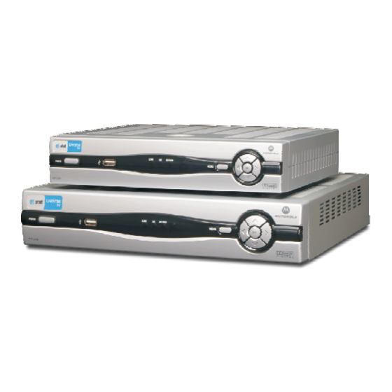
VIP1200 Series Installation Manual OVERVIEW Front Panel All VIP1200 series models have identical front-panel controls and lights. Only the enclosure size varies. The VIP1216 and VIP1225 have larger enclosures to accommodate the hard drive. Item Function POWER If held for less than five seconds, turns the U-verse TV... -
Page 11: Vip1200, Vip1216, And Vip1225 Rear Panel
VIP1200 Series Installation Manual VIP1200, VIP1216, and VIP1225 Rear Panel The VIP1200, VIP1216, and VIP1225 have identical rear-panel connectors arranged in the same order. The VIP1216 and VIP1225 enclosure is slightly larger. Item Description TO WALL Coaxial input for digital signal from your service provider... -
Page 12: Operation
VIP1200 Series Installation Manual OPERATION Turning Power On and Off Press POWER on the front panel to turn the TV receiver on or off. Changing Channels You can change channels in two ways: • Press the up or down button on the TV receiver front panel or the remote control to step through the channel selection. -
Page 13: Connecting Your Tv Receiver
VIP1200 Series Installation Manual CONNECTING YOUR TV RECEIVER This section describes connecting the VIP1200 Series to your home entertainment system. Instructions and diagrams are included for connections to: • High-Definition TV (HDTV) • Home Theater Receiver–Audio • Stereo TV •... -
Page 14: Audio Connection Options
VIP1200 Series Installation Manual S-Video Video only If your standard TV has an S-Video input, use S-VIDEO, which is the highest quality standard-definition video output on the VIP1200. Composite Video only If your standard TV does not have an S-Video video input, use the composite VIDEO OUT connector. -
Page 15: Connecting To An Hdtv - Video Only
VIP1200 Series Installation Manual CONNECTING TO AN HDTV – VIDEO ONLY • Connect an RF coaxial cable to the cable wall outlet and the TO WALL (VIDEO IN) connector on the TV receiver. • If your HDTV has an HDMI input, connect an HDMI cable to the HDMI connector. -
Page 16: Connecting To An Hdtv - Audio Only
VIP1200 Series Installation Manual CONNECTING TO AN HDTV – AUDIO ONLY If your equipment supports it, use the OPTICAL S/PDIF output. Otherwise, use the AUDIO OUT L and R connectors. In most cases, S/PDIF offers better audio quality, including support for Dolby 5.1 Surround Sound. -
Page 17: Connecting Audio To A Home Theater Receiver
VIP1200 Series Installation Manual CONNECTING AUDIO TO A HOME THEATER RECEIVER If your home theater receiver supports it, use the OPTICAL S/PDIF output. Otherwise, use the AUDIO OUT L and R connectors. In most cases, S/PDIF offers better audio quality, including support for Dolby 5.1... -
Page 18: Connecting To A Stereo Tv
VIP1200 Series Installation Manual CONNECTING TO A STEREO TV This video connection method does not support HD video. For more information, see “Connecting an HDTV – Video Only.”... -
Page 19: Connecting To A Stereo Tv And Stereo Vcr
VIP1200 Series Installation Manual CONNECTING TO A STEREO TV AND STEREO VCR This video connection method does not support HD video. For more information, see “Connecting to an HDTV – Video Only.”... -
Page 20: Connecting To A Home Theater Receiver, Tv, And Vcr
VIP1200 Series Installation Manual CONNECTING TO A HOME THEATER RECEIVER, TV, AND VCR This video connection method does not support HD video. For more information, see “Connecting to an HDTV – Video Only.”... -
Page 21: Recording Your Connections
VIP1200 Series Installation Manual RECORDING YOUR CONNECTIONS Use this diagram to record the connections between your home entertainment components. You can use this diagram to reconnect your system if you move the equipment or add new equipment. Disconnect the power from the TV receiver before connecting or changing cable connections. -
Page 22: Troubleshooting
VIP1200 Series Installation Manual TROUBLESHOOTING Before calling your service provider, review this troubleshooting guide. If the suggestions do not help you quickly solve a problem, contact your service provider. Problem Possible Solutions The TV receiver will Verify that the AC power cord is connected to the TV not power on. - Page 23 VIP1200 Series Installation Manual Problem Possible Solutions There is no audio Verify that the Mute button on the remote control has not when viewing TV been pressed. Press Mute on the remote control to channels. restore sound. If the TV receiver audio output is connected to the TV, verify that the Mute button on the TV has not been pressed.