Table of Contents
Advertisement
Quick Links
The World's Most Advanced Detection System
MAX Ci / MAX Ci 360
Dual Antenna Front and Rear
Protection (MAX Ci 360)
360° Directional Alert
Arrows (MAX Ci 360)
Laser Shifters Provide
Speed of Light Protection
The most powerful & complete
protection available
Installation Manual
True Stealth Operation Lets
You Drive 100% Undetected
ESCORT Live App Provides
Crowd Sourced Alerts
GPS Intelligence
Rejects False Alerts
360°
Alerts
Advertisement
Table of Contents

Related Manuals for Escort MAX Ci


Summary of Contents for Escort MAX Ci
- Page 1 The World’s Most Advanced Detection System 360° Alerts MAX Ci / MAX Ci 360 The most powerful & complete protection available True Stealth Operation Lets Dual Antenna Front and Rear You Drive 100% Undetected Protection (MAX Ci 360) 360° Directional Alert...
-
Page 2: Display Module
• Two bezels provided for optional in-dash mounting • Adhesive pads provided for secure mounting Front Laser ShifterMax Sensors • Twin weatherproof sensors • 6-foot cables with waterproof connectors • Mounting hardware and bubble level * Included with ESCORT MAX Ci 360... -
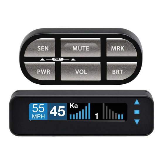
Page 3: Control Module
Solid green when power is ON • Blinking red when receiving a front alert • Blinking blue when receiving a rear alert (ESCORT MAX Ci 360 only) • 6-foot cable with modular connector • Bezel provided mounts easily to instrument pod, dashboard, or console... -
Page 4: Important Notes
Below is a list of error codes which are shown It is recommended that you have a in error messages. The codes help diagnose professional install your new ESCORT MAX Ci . the cause of the error. Installation of this system requires experience and expertise in automotive electronics. -
Page 5: Installation Instructions
Installation Instructions When pulling the inline grommet to the Installation Tips entry point, apply rubbing alcohol to a section of the cable to reduce friction and quickly pull While following the steps throughout this the grommet along the length. manual, please refer to the following recommendations for a professional, trouble- free installation:... - Page 6 (+) to a switched 12-volt • To tighten clamp jaws, insert a 9/64” hex supply. (If ESCORT MAX Ci is left in the “on” key into the screw on the front of each position, it will automatically power on and off clamp and turn clockwise.
- Page 7 Front Laser ShifterMax Front Radar Receiver (Continued) Sensors Find a suitable entry point into the vehicle’s interior. Refer to the Installation Tips section. Feed the harness into the vehicle’s interior and to the Interface. Plug into the connector labeled “Front Receiver. ” Positioning Sensors Install each sensor halfway between the side If entering through a drilled hole, pull the...
- Page 8 F Display Module (Orange Shrink) G Control Module (Blue Shrink) H Concealed Alert Indicator (Gray Shrink) I Rear Radar Receiver (optional, included with ESCORT MAX Ci 360) J Rear ShifterMax Sensors (optional, included with ESCORT MAX Ci 360) ShifterMax Bridge Box...
- Page 9 Optional Components (Included with ESCORT MAX Ci 360)
- Page 10 Preferences section of the Owner’s connector labeled “GPS. ” Manual. Secure and conceal the cable under interior Additional ShifterMax Sensors trim panels. • ESCORT MAX CI users wanting to add rear sensors, two (2) additional ShifterMax Sensors with included hardware are sold separately.
- Page 11 Display Module Display Bezel Mounting Orange Shrink Determine the best location for the Display The supplied display bezel can be used to Module. If installed by a professional, the mount the Display permanently in the dash or customer should be consulted. An optimal console.
- Page 12 Control Module Concealed Alert Blue Shrink Indicator Gray Shrink Determine the best location for the Control Module. If installed by a professional, the Determine the best location for the Alert customer should be consulted. An optimal Indicator. If installed by a professional, the location is easily visible and accessible from customer should be consulted.
-
Page 13: Operation Test
After all components are installed correctly: Follow the same installation instructions as for the Front Radar Receiver but with the Turn ESCORT MAX Ci on by turning on the receiver’s arrow oriented to point out the rear vehicle’s ignition and, if necessary, press the of the vehicle. - Page 14 Designed in the USA ESCORT Inc. 5440 West Chester Road West Chester OH 45069 800.433.3487 EscortRadar.com ©2016 ESCORT, Inc. ESCORT®, Defender®, ESCORT MAX Ci , ESCORT MAX Ci 360 , Laser ShifterMax , TrueLock , AutoSensitivity SpecDisplay , TotalShield , ExpertMeter...