Agilent Technologies 7820A Operating Manual
Gas chromatograph
Hide thumbs
Also See for 7820A:
- Service manual (397 pages) ,
- Manual (294 pages) ,
- Advanced user's manual (130 pages)
Table of Contents
Advertisement
Quick Links
Advertisement
Table of Contents

Related Manuals for Agilent Technologies 7820A


Summary of Contents for Agilent Technologies 7820A
- Page 1 Agilent 7820A Gas Chromatograph Operating Guide Agilent Technologies...
- Page 2 Agilent disclaims all war- calls attention to an operating Agilent Technologies, Inc. as governed by ranties, either express or implied, with procedure, practice, or the like that, if United States and international copyright...
-
Page 3: Table Of Contents
Introduction Where to Find Information Online User Documentation Agilent Customer Portal Chromatography Using a GC The Front View of the Agilent 7820A GC The Back View of the Agilent 7820A GC The Inlets The GC Column and Oven Detectors The Operating Panel... - Page 4 The GC Component Keys The Status Key The Info Key The General Data Entry Keys The Supporting Keys Method Storage and Automation Keys Keypad Functionality When the GC Is Controlled by an Agilent Data System About GC Status in the Software Keypad Indicators Error conditions Blinking setpoint...
- Page 5 Configuration Tasks About the GC IP Address To set the IP address at the GC To Use DHCP to Provide the GC IP Address To restore the default GC IP address To Reconfigure the EPC Module for Another Detector Operating Guide...
- Page 6 Operating Guide...
-
Page 7: Introduction
Agilent 7820AGas Chromatograph Operating Guide Introduction Where to Find Information Chromatography Using a GC The Front View of the Agilent 7820A GC The Back View of the Agilent 7820A GC The Inlets The GC Column and Oven Detectors The Operating Panel... -
Page 8: Where To Find Information
In addition to this document, Agilent provides several learning products that document how to install, operate, maintain, and troubleshoot the Agilent 7820A GC. Before operating your GC, be sure to read the safety and regulatory information included on the Agilent GC and GC/MS Hardware User Information &... -
Page 9: Agilent Customer Portal
Introduction • Operating guides • Maintenance information • Troubleshooting details Agilent Customer Portal Agilent also provides customized information for the products you own through a customer portal. This web service provides many customizable services as well as information related directly to your Agilent products and orders. -
Page 10: Chromatography Using A Gc
Detecting what compounds were in the sample. (This is done in the detector.) During this process, status messages from the Agilent 7820A GC are displayed, and user changes to parameter settings can be made through the software keypad. -
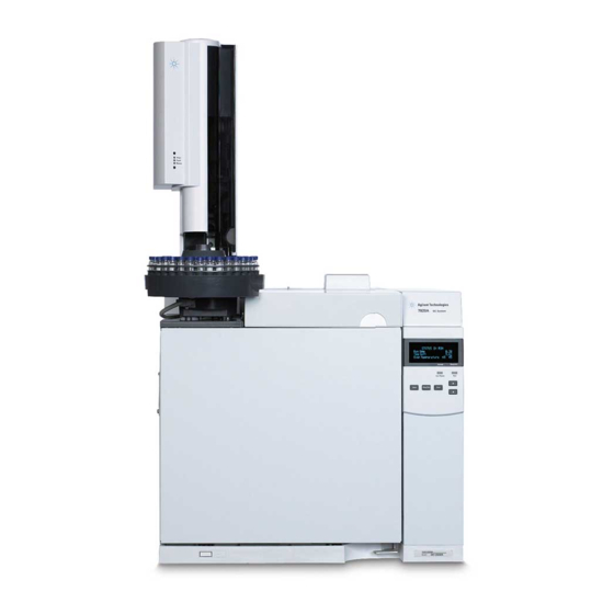
Page 11: The Front View Of The Agilent 7820A Gc
Introduction The Front View of the Agilent 7820A GC Detector cover Detectors Valves (not shown) Inlets Display Keypad Power switch Oven latch Operating Guide... -
Page 12: The Back View Of The Agilent 7820A Gc
Introduction The Back View of the Agilent 7820A GC Inlet vent Gas supply connections Electronic cable connections Oven cooling intake and exhaust vent Power connection Operating Guide... -
Page 13: The Inlets
Introduction The Inlets Inlets are where samples are injected into the GC. The Agilent 7820A GC can have a maximum of two inlets, identified as Front Inlet and Back Inlet. Two inlets—split/splitless and purged packed—are available. The type of inlet chosen is based on the type of analysis being done, the type of sample being analyzed, and the column being used. - Page 14 Valves are most frequently used to sample gases in constantly flowing streams. The Agilent 7820A GC can accommodate up to two gas sampling valves, identified as Valve # 1 and Valve #2. The valves are located inside the gas sampling valve box.
-
Page 15: The Gc Column And Oven
Introduction The GC Column and Oven GC columns are located inside a temperature- controlled oven. Generally, one end of the column is attached to the inlet, while the other end is attached to the detector. Columns vary in length, diameter, and internal coating. Each column is designed for use with different compounds. -
Page 16: Detectors
This signal is generally sent to a data analysis system—such as Agilent ChemStation—where it shows up as a peak on a chromatogram. The Agilent 7820A GC can accommodate up to two detectors, identified as Front Det and Back Det. A complete selection of detectors (FID, TCD, NPD, FPD, µECD, and MSD) is available. -
Page 17: The Operating Panel
Start The display The display shows details of what is currently happening in the Agilent 7820A GC. Use the scroll keys to view additional lines in the display. The display shows current temperatures, flows, pressures, and information about GC readiness. -
Page 18: Alert Tones
Introduction Not Ready Lights when the GC is not yet ready to process a sample and blinks when a fault occurs. Scroll to see which parameters are not ready or what faults have occurred. Lights when the instrument is executing a chromatographic run. -
Page 19: The Keypad
Introduction The keypad The GC has three operating keys. [Stop] Immediately terminates the run. If the GC is in the middle of a run, the data from that run may be lost. Refer to the Advanced User Guide for information on how to restart the GC after pressing [Stop]. - Page 20 Introduction Operating Guide...
-
Page 21: Operating Basics
To Start Up the GC To Shut Down the GC for Less Than a Week To Shut Down the GC for More Than a Week This section describes the tasks that an operator performs when using the Agilent 7820A GC. Agilent Technologies... -
Page 22: Overview
Operating Basics Overview Operating the GC involves the following tasks: • Installing the software keypad. • Setting up the GC hardware for an analytical method. • Starting up the GC. See “To Start Up the GC”. • Preparing the automatic liquid sampler. Install the method- defined syringe;... -
Page 23: Instrument Control
Operating Basics Instrument Control The Agilent 7820A GC is typically controlled by an attached data system such as Agilent EZChrom Elite Compact. Alternately, the GC can be controlled entirely from a software keypad, with output data being sent to an attached integrator for report generation. -
Page 24: Correcting Problems
Operating Basics Correcting Problems If the GC stops operation because of a fault, for example a flow module shutdown after running out of carrier gas, do the following: Use the software keyboard or data system to stop the alert tone. Click [Clear] on the software keyboard or turn off the offending component in the data system. -
Page 25: To Start Up The Gc
Operating Basics To Start Up the GC Successful operation begins with a properly installed and maintained GC. The utility requirements for gases, power supply, venting of hazardous chemicals, and required operational clearances around the GC are detailed in the Site Preparation Checklist Site Preparation Guide. -
Page 26: To Shut Down The Gc For Less Than A Week
Operating Basics To Shut Down the GC for Less Than a Week Wait for the current run to finish. If the active method has been modified, save the changes. Never leave flammable gas flows on if the GC will be unmonitored. WA R N I N G If a leak develops, the gas could create a fire or explosion hazard. -
Page 27: To Shut Down The Gc For More Than A Week
Operating Basics To Shut Down the GC for More Than a Week Load a GC maintenance method and wait for the GC to become ready. For more information about creating maintenance methods, see the Maintaining Your GC manual. (If a maintenance method is not available, set all heated zones to 40 °C.) Turn off the main power switch. - Page 28 Operating Basics Operating Guide...
-
Page 29: Software Keypad Operation
7820A GC Remote Controller (software keypad). This software provides a keypad interface that allows you to connect to and control a 7820A GC. The software keypad provides the same functionality as a real keypad on the GC. For additional information on keypad functionality, see the Advanced User Guide. -
Page 30: To Install The Software Keypad
Software Keypad Operation To Install the Software Keypad Agilent provides 7820A GC Remote Controller software on the Agilent GC and GC/MS Hardware User Information & Utilities DVD. To install the software, insert the DVD into your PC’s DVD drive, then follow the online instructions for installing the 7820A GC documentation. -
Page 31: The Software Keypad
• Clear fault conditions The software keypad can control only one 7820A Series GC at a time. It can connect to any 7820A GC on the PC’s network. Use only one software keypad at a time to connect to a given GC. -
Page 32: To Disconnect From A Gc
Software Keypad Operation Click Connect. The software keyboard window title displays the name or IP address of the connected GC. This information also appears at the bottom of the window. If desired, you can enable AutoConnect to always connect to the selected GC when launching the software keypad. -
Page 33: To Minimize Or Expand The Software Keypad
Software Keypad Operation the new shortcut, then click Store to save it and OK to close the Option dialog. Shortcuts must be unique. Click Default to restore the factory shortcut values. Settings > Option > Log Select the Log tab to display the log entries compiled by the software keypad. -
Page 34: To Get Help
Software Keypad Operation To get help To open the keypad software help, go to Help > Contents. Operating Guide... -
Page 35: The Run Keys
Software Keypad Operation The Run Keys These keys are used to start, stop, and prepare the GC to run a sample. [Prep Run] Activates processes required to bring the GC to the starting condition dictated by the method (such as turning off the inlet purge flow for a splitless injection or restoring normal flow from gas saver mode). -
Page 36: The Gc Component Keys
Software Keypad Operation The GC Component Keys These keys are used to set the temperature, pressure, flow, velocity, and other method operating parameters. To display the current settings, press any one of these keys. More than three lines of information may be available. Use the scroll keys to view additional lines, if necessary. -
Page 37: The Status Key
Software Keypad Operation The Status Key [Status] Toggles between setpoint/actual values for most commonly reviewed parameters and displays “ready,” “not ready,” and “fault” information. When the Not Ready status light is blinking, a fault has occurred. Press [Status] to see which parameters are not ready and what fault has occurred. -
Page 38: The Info Key
Software Keypad Operation The Info Key [Info] Provides help for the currently shown parameter. For example, if Oven Temp is the active line in the display (has a < next to it), [Info] will display the valid range of oven temperatures. -
Page 39: The General Data Entry Keys
Software Keypad Operation The General Data Entry Keys [Mode/Type] Accesses a list of possible parameters associated with a component’s nonnumeric settings. For example, if the GC is configured with a split/splitless inlet and the [Mode/Type] key is pressed, the options listed will be split, splitless, pulsed split, or pulsed splitless. -
Page 40: The Supporting Keys
Software Keypad Operation The Supporting Keys [Time] Displays the current date and time on the first line. The two middle lines show the time between runs, the elapsed time and time remaining during a run, and the last run time and post- time during a post- run. -
Page 41: Method Storage And Automation Keys
Software Keypad Operation Method Storage and Automation Keys These keys are for loading and storing methods and sequences locally on your GC. They cannot be used to access methods and sequences stored by your Agilent ChemStation. [Load] Are used to load and store methods and [Method] sequences on your GC. -
Page 42: Keypad Functionality When The Gc Is Controlled By An Agilent Data System
Software Keypad Operation Keypad Functionality When the GC Is Controlled by an Agilent Data System When an Agilent data system controls the GC, the data system defines the setpoints and runs the samples. The Remote indicator on the software keypad lights when a data system is controlling the GC. -
Page 43: About Gc Status In The Software Keypad
Software Keypad Operation About GC Status in the Software Keypad When the GC is ready to begin a run, the display screen shows STATUS Ready for Injection. Alternatively, when a component of the GC is not ready to begin a run, the Not Ready indicator on the software keypad is lit. -
Page 44: Blinking Setpoint
Software Keypad Operation Blinking setpoint If the system shuts down a gas flow or the oven, Off will blink on the appropriate line of the component’s parameter listing. If there is a detector pneumatics shutdown or failure in another part of the detector, the detector On/Off line of the detector’s parameter list blinks. -
Page 45: About Logs
Software Keypad Operation About Logs Two logs are accessible from the keypad: the run log and the system event log. To access the logs, press [Logs] to toggle to the desired log. The display will indicate the number of entries the log contains. Scroll through the list. Run log The run log is cleared at the start of each new run. - Page 46 Software Keypad Operation Operating Guide...
-
Page 47: Running A Method Or A Sequence From The Software Keypad
Agilent 7820A Gas Chromatograph Operating Guide Running a Method or a Sequence from the Software Keypad Loading, Storing, and Running Methods from the Software Keypad Loading, Storing, and Running Sequences from the Software Keypad This section explains how to load, store, and run a method or sequence using the software keypad, without the use of an Agilent data system. -
Page 48: Loading, Storing, And Running Methods From The Software Keypad
Running a Method or a Sequence from the Software Keypad Loading, Storing, and Running Methods from the Software Keypad To load a method Press [Load]. Press [Method]. Enter the number of the method to be loaded (1 through Press [On/Yes] to load the method and replace the active method. -
Page 49: To Abort A Method
Running a Method or a Sequence from the Software Keypad After the sample is loaded into the syringe, the sample is automatically injected when the GC reaches the ready state. To abort a method Press [Stop]. When you are ready to resume running analyses, load the appropriate sequence or method. -
Page 50: Loading, Storing, And Running Sequences From The Software Keypad
Running a Method or a Sequence from the Software Keypad Loading, Storing, and Running Sequences from the Software Keypad A sequence can specify up to five subsequences to be run, as well as post- run sequences, if defined. Each sequence is stored as a number (from 1 to 9). -
Page 51: To Pause A Running Sequence
Running a Method or a Sequence from the Software Keypad The Run indicator will light and stay lit until the sequence is completed. The sequence continues to run until all subsequences are executed or until the sequence is aborted. To pause a running sequence Press [Seq Control]. -
Page 52: To Resume An Aborted Sequence
Running a Method or a Sequence from the Software Keypad • A running sequence tries to load a method that doesn’t exist. • The sampler is turned off. To resume an aborted sequence Correct the problem. (See "Aborting a sequence".) Press [Seq Control]. - Page 53 Agilent 7820A Gas Chromatograph Operating Guide About Methods, Sequences, and Data Analysis What Is a Method? What Is Saved in a Method? What Happens When You Load a Method? What Is a Sequence? Automating Data Analysis, Method Development, and Sequence...
-
Page 54: About Methods, Sequences, And Data Analysis
About Methods, Sequences, and Data Analysis What Is a Method? A method is the group of settings required to accurately analyze a specific sample. Since every type of sample reacts differently in the GC—some samples require a higher oven temperature, others require a lower gas pressure or a different detector—a unique method must be created for each specific type of analysis. -
Page 55: What Happens When You Load A Method
About Methods, Sequences, and Data Analysis What Happens When You Load a Method? There are two kinds of methods: • The active method—This is sometimes referred to as the current method. The settings defined in this method are the settings the GC is currently maintaining. •... - Page 56 About Methods, Sequences, and Data Analysis Operating Guide...
- Page 57 Agilent 7820A Gas Chromatograph Operating Guide Configuration Tasks About the GC IP Address To set the IP address at the GC To Use DHCP to Provide the GC IP Address To restore the default GC IP address To Reconfigure the EPC Module for Another Detector This section describes a several configuration tasks that may be required as part of normal operation.
-
Page 58: About The Gc Ip Address
Configuration Tasks About the GC IP Address From the factory, the GC is set to: IP address 192.168.0.26 Subnet Mask 255.255.255.0 Gateway 192.168.0.1 The installation procedures assume that you will connect to the GC using this address. However, after installation you may need to change the GC IP address or set it to use DHCP. -
Page 59: To Set The Ip Address At The Gc
To set the IP address at the GC Start the software keyboard. From the Windows® Start program menu, Agilent > All Programs > Agilent Technologies > 7820A GC Remote Controller. Connect to the GC. Go to Connection > Connect…. In the Target field, enter the current GC IP address. -
Page 60: To Use Dhcp To Provide The Gc Ip Address
Configuration Tasks To Use DHCP to Provide the GC IP Address To set the GC to use DHCP: Turn off the GC. While pressing and holding [Prep Run] and [Stop] on the GC keypad, turn on the GC. This will set the GC to use DHCP to obtain an IP address. -
Page 61: To Restore The Default Gc Ip Address
Configuration Tasks To restore the default GC IP address During installation and sometimes during operation, you may need to reset the GC IP address or change its IP addressing mode. To restore the default IP address, press and hold the [Prep Run] key while power cycling the GC. -
Page 62: To Reconfigure The Epc Module For Another Detector
Agilent provides a configurable flow module that supplies gas flows to the detectors installed in the GC. However, since the 7820A GC is a single channel instrument, a single flow module can supply gases to only one detector at a time. - Page 63 Configuration Tasks Flow module Gas line routing slot for detector in use with back flow module (Epc 2) Detector tubing (in use) Detector tubing Gas line routing slot for (not in use) detector in use with front flow module (Epc 1) Figure 1 Example back detector EPC flow module with FID tubing attached Click [Config][Lite EPC#].
- Page 64 Configuration Tasks After the GC reboots, the software keypad will temporarily loose communication with the GC. When the GC completes reboot, click Reconnect, or simply wait a few moments. Turn off the new detector and its gas flows. Turning off the detector and its flows protects the detector and prevents shutdown errors while you connect any new gas supplies.
- Page 65 Configuration Tasks Carefully arrange the new detector tubing so that it fits through the correct routing slot. See Figure Route the tubing for the unused detector tubing through the other routing slot, and gently push its fittings into the open manifold space. See Figure If the detector gas types differ between the new detector and the old detector, connect the new gas supplies to the...
- Page 66 Configuration Tasks Operating Guide...