Table of Contents
Advertisement
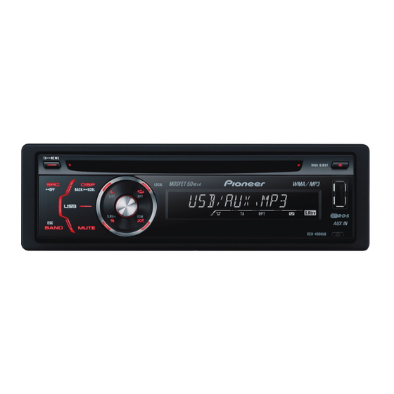
CD RDS RECEIVER
DEH-4000UB
CD RECEIVER
DEH-3050UB
DEH-3050UB
This service manual should be used together with the following manual(s):
Model No.
Order No.
CX-3240
CRT4050
For details, refer to "Important Check Points for Good Servicing".
PIONEER CORPORATION
PIONEER ELECTRONICS (USA) INC. P.O. Box 1760, Long Beach, CA 90801-1760, U.S.A.
PIONEER EUROPE NV Haven 1087, Keetberglaan 1, 9120 Melsele, Belgium
PIONEER ELECTRONICS ASIACENTRE PTE. LTD. 253 Alexandra Road, #04-01, Singapore 159936
PIONEER CORPORATION 2007
Mech.Module
S10.5COMP2-iPod/USB
CD Mech. Module : Circuit Descriptions, Mech. Descriptions, Disassembly
4-1, Meguro 1-chome, Meguro-ku, Tokyo 153-8654, Japan
DEH-4000UB/XS/EW5
/XS/ES
/XU/CN5
Remarks
ORDER NO.
CRT4052
/XS/EW5
K-ZZA. NOV. 2007 Printed in Japan
Advertisement
Table of Contents

Related Manuals for Pioneer DEH-4000UB/XS/EW5


Summary of Contents for Pioneer DEH-4000UB/XS/EW5
- Page 1 PIONEER CORPORATION 4-1, Meguro 1-chome, Meguro-ku, Tokyo 153-8654, Japan PIONEER ELECTRONICS (USA) INC. P.O. Box 1760, Long Beach, CA 90801-1760, U.S.A. PIONEER EUROPE NV Haven 1087, Keetberglaan 1, 9120 Melsele, Belgium PIONEER ELECTRONICS ASIACENTRE PTE. LTD. 253 Alexandra Road, #04-01, Singapore 159936 PIONEER CORPORATION 2007 K-ZZA.
-
Page 2: Safety Information
Transistors Q101 in PCB drive the laser diodes. When Q101 is shorted between their terminals, the laser diodes will radiate beam. If the top cover is removed with no disc loaded while such short-circuit is continued, the naked eyes may be exposed to the laser beam. DEH-4000UB/XS/EW5... - Page 3 CAUTION Danger of explosion if battery is incorrectly replaced. Replaced only with the same or equivalent type recommended by the manufacture. Discord used batteries according to the manufacture's instructions. DEH-4000UB/XS/EW5...
- Page 4 To protect products from damages or failures during transit, the shipping mode should be set or the shipping screws should be installed before shipment. Please be sure to follow this method especially if it is specified in this manual. DEH-4000UB/XS/EW5...
-
Page 5: Table Of Contents
10. SCHEMATIC DIAGRAM..........................46 10.1 OVERALL CONNECTION DIAGRAM(GUIDE PAGE)................46 10.2 KEYBOARD UNIT ..........................52 10.3 CD MECHANISM MODULE(GUIDE PAGE)...................54 10.4 WAVEFORMS............................60 11. PCB CONNECTION DIAGRAM ........................64 11.1 TUNER AMP UNIT ..........................64 11.2 KEYBOARD UNIT...........................68 11.3 CD CORE UNIT(S10.5COMP2-USB).....................70 12. ELECTRICAL PARTS LIST...........................72 DEH-4000UB/XS/EW5... -
Page 6: Service Precautions
Compared with eutectic solders, lead-free solders have higher bond strengths but slower wetting times and higher melting temperatures (hard to melt/easy to harden). The following lead-free solders are available as service parts: Parts numbers of lead-free solder: GYP1006 1.0 in dia. GYP1007 0.6 in dia. GYP1008 0.3 in dia. DEH-4000UB/XS/EW5... -
Page 7: Specifications
2. SPECIFICATIONS 2.1 SPECIFICATIONS - EW5 Model Backup current ........5 mA or less DEH-4000UB/XS/EW5... - Page 8 - ES Model Backup current ........5 mA or less DEH-4000UB/XS/EW5...
-
Page 9: Disc/Content Format
- CN5 Model Backup current ........5 mA or less 2.2 DISC/CONTENT FORMAT DEH-4000UB/XS/EW5... -
Page 10: Panel Facilities
2.3 PANEL FACILITIES DEH-4000UB/XS/EW5... - Page 11 DEH-4000UB/XS/EW5...
- Page 12 DEH-4000UB/XS/EW5...
-
Page 13: Connection Diagram
2.4 CONNECTION DIAGRAM - EW5 Model DEH-4000UB/XS/EW5... - Page 14 - ES, CN5 Model DEH-4000UB/XS/EW5...
-
Page 15: Basic Items For Service
Unit Number : (EW5) (S10.5COMP2-USB) Unit Number : (ES) Unit Name : Keyboard Unit Unit Number : (CN5) Unit Name : Keyboard Unit Unit Number : CWX3527 Unit Name : CD Core Unit (S10.5COMP2-USB) Tuner Amp Unit Keyboard Unit DEH-4000UB/XS/EW5... -
Page 16: Jigs List
GEM1045 CD Mechanism Module Before shipping out the product, be sure to clean the following portions by using the prescribed cleaning tools: Portions to be cleaned Cleaning tools CD pickup lenses Cleaning liquid : GEM1004 Cleaning paper : GED-008 DEH-4000UB/XS/EW5... - Page 17 DEH-4000UB/XS/EW5...
-
Page 18: Block Diagram
MIXER, IF AMP DET, FM MPX, RDS DECODER RF adj ANT adj CF52 → 3.3V 2.5V 2.5V 3.3V TUNL VDD3.3V AUXL AUXGND SYSTEM DEH-4000UB/XS/EW5 CONTROLLER IC 601(2/2) DEH-3050UB/XS/ES VST,VCK PEG475A: PEG409A: B , C DEH-3050UB/XU/CN5 CN621 REAR AUXL MUTE AUXGND KEY1 KEYD... - Page 19 S Rtrv JOYST JOYST OYST SWVDD SWVDD SWVDD Q851 WVDD X1801 IC1802 Q852 OPT IN 5MHz GP1UX51RK LCD DRIVER/ B , C KEY CONTROLLER REMOTE CONTROL IC1801 SENSOR DPDT DPDT PD6538A DPDT KYDT LCD1801 KYDT KYDT DSENS DSENS SENS DEH-4000UB/XS/EW5...
- Page 20 22 AUDIOGND audio ground Ground of audio block 23 L ch O L channel output FM stereo “L-ch” signal output or AM audio output 24 R ch O R channel output FM stereo “R-ch” signal output or AM audio output DEH-4000UB/XS/EW5...
- Page 21 22 AUDIOGND audio ground Ground of audio block 23 L ch O L channel output FM stereo “L-ch” signal output or AM audio output 24 R ch O R channel output FM stereo “R-ch” signal output or AM audio output DEH-4000UB/XS/EW5...
- Page 22 - LCD(YAW5091) DEH-4000UB/XS/EW5...
-
Page 23: Diagnosis
In case of the above signal, the communication Source keys with Grille microcomputer may fail. operative If the time interval is not 300 msec, the oscillator may be defective. Source ON SYSPW H Pin 48 Completes power-on operation.(After that, proceed to each source operation.) DEH-4000UB/XS/EW5... -
Page 24: Error Code List
Remarks: Mechanical errors are not displayed (because a CD is turned off in these errors). Unreadable TOC does not constitute an error. An intended operation continues in this case. Upper digits of an error code are subdivided as shown below: 1x: Setup relevant errors, 3x: Search relevant errors, Ax: Other errors. DEH-4000UB/XS/EW5... - Page 25 Disconnect the USB device, and connect it again. ERROR-19 Communication failure Change to a different source. Then, return to the USB. USB device is not formatted with FAT16 or ERROR-23 Format the USB device with FAT16 or FAT32. FAT32 DEH-4000UB/XS/EW5...
-
Page 26: Connector Function Description
REAR OUTPUT OR SUBWOOFER OUTPUT POWER SUPPLY 1. FR+ 9. TEL 2. RR+ 10. NC 3. FR- 11. B.REM 4. RR- 12. NC 5. FL+ 13. NC 6. RL+ 14. ACC 7. FL- 15. GND 8. RL- 16. B.UP DEH-4000UB/XS/EW5... -
Page 27: Service Mode
1k ohms in series. The load and eject operation is not guarantied with the mechanism upside down. If the mechanism is blocked due to mistaken eject operation, reset the product or turn off and on the ACC to restore it. DEH-4000UB/XS/EW5... - Page 28 3 Press the C key to change display/non-display of key names. When the non-display mode is selected for the K1 - K6 key names, "A key" and "B key" are invalid. C key • Pressing the A key or B key does not work. DEH-4000UB/XS/EW5...
- Page 29 • When the power is turned on/off the jump mode is reset to the Single TR (91) while the gain of the RFAMP is reset to 0 dB. At the same time all the self-adjusting values shall return to the default setting. DEH-4000UB/XS/EW5...
-
Page 30: Disassembly
Fig.2 Holder Case Removing the Case and Panel (Fig.3,4) Remove the Case.(Fig.3) Fig.3 Take off four picks of the part of the arrow Panel and then remove the Panel.(Fig.4) Fig.4 DEH-4000UB/XS/EW5... - Page 31 Push the place of the arrows and then remove the Panel Assy. Fig.5 Panel Assy Fig.6 Removing the CD Mechanism Module (Fig.7) Remove the four screws. Disconnect the cable and then remove the CD Mechanism Module. Fig.7 CD Mechanism Module DEH-4000UB/XS/EW5...
- Page 32 Removing the Tuner Amp Unit (Fig.8,9) Remove the three screws.(Fig.8) Fig.8 Tuner Amp Unit Straighten the tabs at four locations indicated.(Fig.9) Remove the screw and then remove the Tuner Amp Unit.(Fig.9) Fig.9 DEH-4000UB/XS/EW5...
- Page 33 3. While lifting the Carriage Mechanism, Upper Frame remove it from the three Dampers. Caution: When assembling, be sure to apply some alcohol to the Dampers and assemble the mechanism in a clamped state. Damper Carriage Mechanism Damper Lower Frame DEH-4000UB/XS/EW5...
- Page 34 Assemble the sub unit side of the Pickup, taking the plate (Chassis) in-between. When treating the leads of the Load Carriage Motor Assy, do not make them loose over the Feed Screw. Poly Washer Change Arm Inner Holder Pickup Lock Arm Feed Screw Planet Gear Pickup Rack Chassis Pickup DEH-4000UB/XS/EW5...
-
Page 35: Each Setting And Adjustment
The frequency of the clock signal is 468 750 Hz that is one 32th of the fundamental frequency. The clock signal should be 468 750 Hz (-10 Hz, +15 Hz) If the clock signal out of the range, the X’tal (X601) should be replaced with new one. DEH-4000UB/XS/EW5... -
Page 36: Checking The Grating After Changing The Pickup Unit
Because of eccentricity in the disc and a slight misalignment of the clamping center the grating waveform may be seen to "wobble" ( the phase difference changes as the disc rotates). The angle specified above indicates the average angle. Hint Reloading the disc changes the clamp position and may decrease the "wobble". DEH-4000UB/XS/EW5... - Page 37 Grating waveform Ech -> Xch 20 mV/div, AC Fch -> Ych 20 mV/div, AC 0 degrees 30 degrees 45 degrees 60 degrees 75 degrees 90 degrees DEH-4000UB/XS/EW5...
-
Page 38: Exploded Views And Parts List
Screw adjacent to mark on the product are used for disassembly. For the applying amount of lubricants or glue, follow the instructions in this manual. (In the case of no amount instructions,apply as you think it appropriate.) 9.1 PACKING DEH-4000UB/XS/EW5... - Page 39 Battery See Contrast table(2) Contain Box See Contrast table(2) Cord Assy See Contrast table(2) Protector YHP5039 (2) CONTRAST TABLE DEH-4000UB/XS/EW5, DEH-3050UB/XS/ES and DEH-3050UB/XU/CN5 are constructed the same except for the following: Mark Description DEH-4000UB/XS/EW5 DEH-3050UB/XS/ES DEH-3050UB/XU/CN5 Cord Assy CDP1015 Not used...
-
Page 40: Exterior(1)
9.2 EXTERIOR(1) DEH-4000UB/XS/EW5... - Page 41 YNS5305 IC(IC921) NJM2388F84 Tuner Amp Unit See Contrast table(2) Transistor(Q702, Q911) 2SD2396 Screw BPZ26P080FTC (2) CONTRAST TABLE DEH-4000UB/XS/EW5, DEH-3050UB/XS/ES and DEH-3050UB/XU/CN5 are constructed the same except for the following: Mark Description DEH-4000UB/XS/EW5 DEH-3050UB/XS/ES DEH-3050UB/XU/CN5 NOTE Sheet Not used Not used...
-
Page 42: Exterior(2)
9.3 EXTERIOR(2) DEH-4000UB/XS/EW5... - Page 43 Cord Assy See Contrast table(2) Cover YNS5304 Lighting Conductor YNV5137 See Contrast table(2) Connector(CN1801) CKS5663 (2) CONTRAST TABLE DEH-4000UB/XS/EW5, DEH-3050UB/XS/ES and DEH-3050UB/XU/CN5 are constructed the same except for the following: Mark Description DEH-4000UB/XS/EW5 DEH-3050UB/XS/ES DEH-3050UB/XU/CN5 Remote Control Assy Not used CXC8885...
-
Page 44: Cd Mechanism Module
9.4 CD MECHANISM MODULE 43 10 (1) : GEM1024 : GEM1045 DEH-4000UB/XS/EW5... - Page 45 Bracket CND2583 CND3831 Lever CND2585 CND2586 Bracket CND2587 CND2588 Lever CND2589 Holder CNV9522 Gear CNV7207 Gear CNV9513 Gear CNV7209 Gear CNV9514 Gear CNV9515 Gear CNV9516 Rack CNV9517 CNV7216 Roller CNV8189 Gear CNV9518 Guide CNV9519 Gear CNV7595 Guide CNV9520 CNV7805 DEH-4000UB/XS/EW5...
-
Page 46: Schematic Diagram
2SA1036K C508 C503 R503 Q842 RT1N141M-11 220P R502 R511 USB5V CN803 DGND SW5V SWVDD R806 JOYST USBGND 2R2K DPDT 2R2K DPDT KYDT R807 KYDT R804 R814 ILMGND CN1801 2R2K ROT1 R805 R815 ROT0 ILMB 2R2K ILM+ US5V DSEN DSENS DEH-4000UB/XS/EW5... - Page 47 Therefore, when replacing, be sure to use parts of discrete resistors. are expressed as : identical designation. Symbol indicates a capacitor. No differentiation is made between chip capacitors and 0.022 R022 R825 /DSENS discrete capacitors. USDP USDM DEH-4000UB/XS/EW5...
- Page 48 DEH-4000UB/XS/EW5...
- Page 49 DEH-4000UB/XS/EW5...
- Page 50 DEH-4000UB/XS/EW5...
- Page 51 DEH-4000UB/XS/EW5...
-
Page 52: Keyboard Unit
10.2 KEYBOARD UNIT REGION1 BUTTON REGION2 TA/NEWS MUTE ES,CN5 CLOCK SW/BASS EJECT REGION1 REGIO SRC/OFF DISP/BACK/SCRL RPT/LO S.Rt LIST BAND/ESC ES,CN5 LCD DRIVER/ KEY CONTROLLER 100K 5.00MHz DEH-4000UB/XS/EW5... - Page 53 KEYBOARD UNIT REGION2 MUTE SW/BASS REGION2 RPT/LOCAL 3R3K 2R2K S.Rtrv 2R2K MC2848-11 MC2846-11 2R2K EW5,ES CN803 EW5,ES DEH-4000UB/XS/EW5...
-
Page 54: Cd Mechanism Module(Guide Page)
10.3 CD MECHANISM MODULE(GUIDE PAGE) PICKUP UNIT(P10.5)(SERVICE) SWITCHES: CD CORE UNIT(S10.5COMP2-USB) S901:HOME SWITCH..ON-OFF S903:DSCSNS SWITCH..ON-OFF S904:12EJ SWITCH....ON-OFF S905:8EJ SWITCH....ON-OFF The underlined indicates the switch position. M1 CXC7134 SPINDLE MOTOR M2 CXC4026 LOADING/CARRIAGE MOTOR CD DRIVER DEH-4000UB/XS/EW5... - Page 55 CD CORE UNIT(S10.5COMP2-USB) SIGNAL LINE FOCUS SERVO LINE TRACKING SERVO LINE CARRIAGE SERVO LINE SPINDLE SERVO LINE PE5611B DEH-4000UB/XS/EW5...
- Page 56 DEH-4000UB/XS/EW5...
- Page 57 CN701 DEH-4000UB/XS/EW5...
- Page 58 DEH-4000UB/XS/EW5...
- Page 59 DEH-4000UB/XS/EW5...
-
Page 60: Waveforms
500 mV/div 2 ms/div 1 V/div s/div μ %RFAGC 500 mV/div 500 mV/div 500 mV/div 9TIN 500 mV/div Focus Search waveform Track Open waveform 1 Track Jump waveform Ref.: Ref.: Ref.: REFO REFO REFO Mode: Mode: Mode: TEST TEST TEST DEH-4000UB/XS/EW5... - Page 61 REFO Mode: Mode: Mode: Normal Normal Normal 1 V/div 50 ns/div 2 V/div 50 ms/div 2 V/div 50 ms/div 1 V/div 2 V/div 2 V/div USB Play USB device inserting to USB connector. CD Play with USB device connecting. DEH-4000UB/XS/EW5...
- Page 62 2 V/div 50 ms/div 2 V/div ACC OFF with USB device connecting. DEH-4000UB/XS/EW5...
- Page 63 DEH-4000UB/XS/EW5...
-
Page 64: Pcb Connection Diagram
Chip Part IC921 C923 D901 Q911 D552 D903 D971 R955 L901 C922 D904 D551 L951 D931 D932 D911 R912 C913 D912 Q702 C911 L101 CN251 D701 R701 C703 D502 CN701 C502 L501 CN701 C501 C708 BZ601 L852 CN803 CN1801 DEH-4000UB/XS/EW5... - Page 65 C355 C353 C354 C356 C405 L161 Y401 C351C352 C165 D551 L951 C971 L401 C162 C160 C183 L101 D181 CN622 C401 X601 L601 C605 D171 C177 C607 L602 C962 L403 L171 C408 C172 C174 R414 D842 D841 R843 C842 FRONT DEH-4000UB/XS/EW5...
- Page 66 C606 IC961 R962 C176 R175 R171 R173 R805 C171 R174 D172 R833 R172 C178 R606 R804 IC401 R176 Q171 C175 C410 IC171 C404 Q841 R841 C173 R809 R842 Q843 R803 R816 R845 Q842 R824 R835 R819 Q844 R844 C841 DEH-4000UB/XS/EW5...
- Page 67 R707 R506 IC702 C710 R503 R616 R704 C709 R502 R713 R709 C503 R511 R512 R513 R849 C508 R851 R852 R807 Q852 R806 Q851 R819 C851 D809 R836 R832 C801 R853 D806 D805 D803 D801 D810 D808 D804 D802 D807 DEH-4000UB/XS/EW5...
-
Page 68: Keyboard Unit
11.2 KEYBOARD UNIT KEYBOARD UNIT SIDE A DEH-4000UB/XS/EW5... - Page 69 KEYBOARD UNIT SIDE B CN803 DEH-4000UB/XS/EW5...
-
Page 70: Cd Core Unit(S10.5Comp2-Usb)
11.3 CD CORE UNIT(S10.5COMP2-USB) CD CORE UNIT(S10.5COMP2-USB) SIDE A PICKUP UNIT(P10.5)(SERVICE) CN701 REFO1 HOME LOADING/CARRIAGE MOTOR SPINDLE MOTOR DEH-4000UB/XS/EW5... - Page 71 CD CORE UNIT(S10.5COMP2-USB) SIDE B 12EJ DSCSNS DEH-4000UB/XS/EW5...
-
Page 72: Electrical Parts List
D 951 (B,108,109) Diode(EW5) MC2848-11 IC 961 (B,98,33) IC S-80835CNMC-B8U ZNR401 (B,165,113) Surge Protector IMSA-6801-01Y901 Q 351 (B,166,125) Transistor RT3N66M L 161 (A,122,99) Inductor LAU2R2K Q 353 (B,135,125) Transistor(ES,CN5) RT3N66M L 401 (A,150,90) Inductor LAU1R0K Q 401 (B,156,40) Transistor(EW5) UMH1N DEH-4000UB/XS/EW5... - Page 73 (A,157,23) RD1/4PU4R7J R 813 (B,92,37) RS1/16S104J R 415 (B,156,42) (EW5) RS1/16S221J R 814 (B,87,37) RS1/16S102J R 421 (B,155,86) RS1/16S0R0J R 815 (B,85,37) RS1/16S102J R 451 (B,121,117) RS1/16S103J R 816 (B,118,19) RS1/16S1R0J R 452 (B,119,121) RS1/16S221J R 825 (B,77,49) RS1/16S102J DEH-4000UB/XS/EW5...
- Page 74 C 355 (A,130,103) (ES,CN5) CEJQ2R2M50 IC 1801 (B,30,113) IC PD6538A C 356 (A,147,103) (ES,CN5) CEJQ2R2M50 IC 1802 (A,30,161) Remote IC(ES) GP1UX51RK C 401 (A,155,55) CEJQ470M6R3 D 1801 (B,32,149) Diode MC2848-11 C 402 (B,158,56) CKSRYB103K50 D 1802 (B,32,146) Diode MC2846-11 DEH-4000UB/XS/EW5...
- Page 75 (B,37,38) RS1/16S332J R 1824 (B,37,40) RS1/16S822J C 1801 (B,38,141) (ES) CKSYF106Z10 R 1825 (B,37,41) RS1/16S333J C 1802 (B,34,140) CKSRYF104Z25 R 1831 (B,35,41) RS1/16S473J C 1803 (B,32,140) CKSRYF104Z25 R 1832 (B,36,143) RS1/16S103J C 1804 (B,31,140) CKSRYF104Z25 R 1833 (B,40,144) RS1/16S2R2J DEH-4000UB/XS/EW5...
- Page 76 C 239 (B,47,52) CCSSCH220J50 R 237 (A,24,35) RS1/16SS151J C 240 (A,38,61) CKSSYB104K10 R 240 (B,14,26) RS1/16S473J C 243 (B,22,41) CKSQYB475K6R3 R 241 (B,14,25) RS1/16SS103J C 250 (A,52,48) CKSSYB102K50 R 244 (B,22,55) RS1/16SS473J C 251 (A,52,46) CKSSYB102K50 R 254 (A,26,64) RS1/16SS104J DEH-4000UB/XS/EW5...
- Page 77 C 303 (A,36,19) CKSSYB472K25 C 304 (A,36,21) CKSSYB223K16 C 307 (A,22,11) CKSRYB104K16 C 308 (B,11,18) CKSRYB105K10 C 703 (B,15,35) CCSSCH101J50 C 704 (B,12,36) CKSSYB102K50 C 711 (A,31,25) CKSSYB104K10 Miscellaneous Parts List Pickup Unit(P10.5)(Service) CXX1942 Motor Unit(SPINDLE) CXC7134 Motor Unit(LOADING/CARRIAGE) CXC4026 DEH-4000UB/XS/EW5...