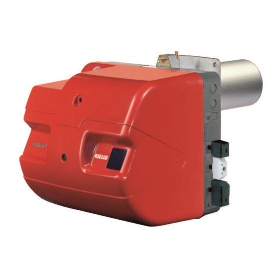
Riello RS 34 MZ Installation, Use And Maintenance Instructions
Blown type gas burners progressive two-stage operation
Hide thumbs
Also See for RS 34 MZ:
- Installation, use and maintenance instructions (77 pages) ,
- Installation, use and maintenance instructions (52 pages) ,
- Installation, use and maintenance instructions (44 pages)
Table of Contents
Advertisement
Available languages
Available languages
Installation, use and maintenance instructions
Instrucciones de instalación, uso y mantenimiento
Instruções de Instalação, Funcionamento e Manutenção
Blown type gas burners
GB
Quemadores de gas de aire soplado
E
Queimadores a gás com ar insuflado
P
Progressive two-stage operation
Funcionamiento a dos llamas progresivas
Funcionamento a duas chamas progressivo
CODE - CÓDIGO
3789010
3789011
3789110
3789111
3789140
3789141
MODEL - MODELO
RS 34 MZ
RS 34 MZ
RS 44 MZ
RS 44 MZ
RS 44 MZ
RS 44 MZ
TYPE - TIPO
883 T
883 T
884 T
884 T
884 T
884 T
2916260 (0) - 11/2006
Advertisement
Chapters
Table of Contents

Related Manuals for Riello RS 34 MZ


Summary of Contents for Riello RS 34 MZ
- Page 1 Progressive two-stage operation Funcionamiento a dos llamas progresivas Funcionamento a duas chamas progressivo CODE - CÓDIGO MODEL - MODELO TYPE - TIPO 3789010 RS 34 MZ 883 T 3789011 RS 34 MZ 883 T 3789110 RS 44 MZ 884 T...
- Page 2 EC Declaration of Conformity, and has been manufactured and distributed in compliance with the require- ments defined in the Legislative Decree of 8 January 2004. Type of product: Blown type gas burners Model 883 T 884 T RS 34 MZ RS 44 MZ average NOx Values (mg/kWh) measured * max CO (mg/kWh) * Natural gas operation (Fam.
- Page 3 The burner has EC marking and conforms to the basic requisites of the following Directives: – EC Reg. N.: 0085BR0381 in accordance with 90/396/EEC; – Electromagnetic Compatibility Directive 89/336/EEC; – Low voltage directive 73/23/EEC; – Machine Directive 98/37/EEC; – Yield Directive 92/42/EEC. The burner meets protection level of IP 40 as EN 60529.
-
Page 4: Table Of Contents
INDEX TECHNICAL DATA ....... . page 2 Variants ..........2 Accessories . -
Page 5: Technical Data
TECHNICAL DATA MODEL RS 34 MZ RS 44 MZ RS 44 MZ TYPE 883 T 884 T 884 T OUTPUT 2nd stage 125 - 390 200 - 550 200 - 550 108 - 336 172 - 473 172 - 473 Mcal/h min. -
Page 6: Burner Description
- one for “1st - 2nd stage operation” 19 Motor contact maker and thermal cut-out with reset button (RS 44 MZ) 20 Motor capacitor (RS 34 MZ) 21 Control box with lockout pilot light and reset button 22 Sockets for electrical wiring... -
Page 7: Firing Rates
• a MAXIMUM OUTPUT, selected within area A, • and a MINIMUM OUTPUT, which must not be lower than the minimum limit in the diagram: RS 34 MZ = 70 kW RS 44 MZ = 100 kW Attention The FIRING RATE values have been obtained considering an ambient temperature of 20 °C, a... -
Page 8: Gas Pressure
5.1 - 2 =3.1 mbar A pressure of 3.1 mbar (column 1) corresponds in the table RS 34 MZ to an output of 250 kW. This value serves as a rough guide, the effective delivery must be measured at the gas meter. -
Page 9: Installation
Any other position could compromise the correct operation of the appliance. Installation 5 is forbidden, for safety reasons. RS 34 MZ BOILER PLATE (B) RS 44 MZ Pierce the closing plate of the combustion chamber, as in (B). The position of the threaded... -
Page 10: Setting The Combustion Head
SETTING THE COMBUSTION HEAD Installation operations are now at the stage where the blast tube and the pipe coupling are secured to the boiler as shown in fig.(A). It is therefore particularly easy to adjust the combus- tion head. Air adjustment (A) Rotate the screw 1)(A) until the notch on the lamina 2)(A) corresponds with the surface of the plate 3)(A). -
Page 11: Gas Feeding Line
C.T.= Checking device for gas valves seal: GAS TRAINS L BURNER - = Gas train without gas valve leak detection control device; device that Code Model Ø C.T. RS 34 MZ RS 44 MZ Code Code ordered separately 3970500 MB-DLE 405 3/4”... -
Page 12: Adjustment Prior To Firing
ADJUSTMENTS PRIOR TO FIRING MIN GAS PRESSURE SWITCH AIR PRESSURE SWITCH ATTENTION THE FIRST FIRING MUST BE CARRIED OUT BY QUALIFIED PERSONNEL WITH THE RIGHT INSTRUMENTS. The adjustment of the combustion head, air, was described on page 7. In addition, the following adjustments must also be made: - open manual valves up-line from the gas train. -
Page 13: Burner Calibration
BURNER CALIBRATION The optimum calibration of the burner requires an analysis of the flue gases at the boiler outlet. Adjust successively: Burner off 1st stage 1 - 2nd stage burner output 2 - 1st stage burner output 3 - Intermediate outputs Burner on 2nd stage 4 - Air pressure switch... -
Page 14: 1St Stage Burner Output
Adjusting air delivery Progressively adjust the end profile of cam 4)(A) by turning the cam adjustment screws as they appear through the access opening 6)(A). - Lock the screws to increase air delivery. - Loose the screws to reduce air delivery. 2 - 1ST STAGE BURNER OUTPUT Burner power in 1st stage operation must be selected within the firing rate range shown on... -
Page 15: Air Pressure Switch
4 - AIR PRESSURE SWITCH (A) AIR PRESSURE SWITCH 4)(A)p. 3 Adjust the air pressure switch after having per- formed all other burner adjustments with the air pressure switch set to the start of the scale (A). With the burner operating in 1st stage, increase adjustment pressure by slowly turning the rela- tive knob clockwise until the burner locks out. -
Page 16: Burner Operation
BURNER OPERATION NORMAL FIRING BURNER START UP (A) (n° = seconds from instant 0) • : Remote control TL closes. Servomotor starts: it rotates during opening up to the angle set on cam St1. After about 3s: • 0 s : The control box starting cycle begins. •... -
Page 17: Final Checks
FINAL CHECKS (with the burner working): • disconnect a wire of the minimum gas pres- sure switch; • switch on the thermostat/pressure switch TL; • switch on the thermostat/pressure switch TS; the burner must stop. • disconnect the air adduction tube of the pres- sure switch;... -
Page 18: Switchboard Maintenance
TO OPEN THE BURNER (A): OPENING THE BURNER - Switch off the electrical power. - Remove screw 1) and withdraw casing 2). - Disengage the articulated coupling 3) from the graduated sector 4). - Remove screw 5) only if the models have a long head, retract the burner on guides 6) for around 100 mm. - Page 19 BURNER START-UP CYCLE DIAGNOSTICS During start-up, indication is according to the following table: COLOUR CODE TABLE Sequences Colour code Pre-purging Firing phase Operation, flame ok Operating with weak flame signal Electrical supply lower than ~ 170V Lockout Extraneous light Key to layout: Yellow Green RESETTING THE CONTROL BOX AND USING DIAGNOSTICS...
- Page 20 SIGNAL FAULT PROBABLE CAUSE SUGGESTED REMEDY 2x blinks After pre-purge and safety - The solenoid VR allows little gas through ....Increase time, the burner locks out - Solenoid valves VR or VS fail to open .
-
Page 21: Appendix
The electrical wiring must be carried out in conformity with the regulations in force in the countries of destination, and by qualified personnel. Riello S.p.A. cannot accept any responsibility for modifica- tions or connections other than those shown in these dia- grams. - Page 22 CE, y ha sido producida y puesta en circulación de acuerdo con las exigencias defi- nidas en al D.L. del 8 de enero 2004. Tipo de producto: Quemador de gas con aire soplado Modelo 883 T 884 T RS 34 MZ RS 44 MZ media NOx (mg/kWh) Valores medidos* CO máx (mg/kWh) * Funcionamiento con gas natural (Fam.
- Page 23 El quemador posee la marca CE y es conforme a los requisitos fundamentales de las siguientes Directivas: – CE Reg. N.: 0085BR0381 según 90/396/CEE; – Directiva Compatibilidad Electromagnética 89/336/CEE; – Directiva Baja Tensión 73/23/CEE; – Directiva Máquinas 98/37/CEE; – Directiva Rendimientos 92/42/CEE; Grado de protección de los quemadores IP 40 según EN 60529.
- Page 24 ÍNDICE DATOS TÉCNICOS ......página Nº 2 Versiones constructivas ........2 Accesorios .
-
Page 25: Datos Técnicos
DATOS TÉCNICOS MODELO RS 34 MZ RS 44 MZ RS 44 MZ TIPO 883 T 884 T 884 T POTÊNCIA 125 - 390 200 - 550 200 - 550 llama 108 - 336 172 - 473 172 - 473 Mcal/h min. -
Page 26: Descripción Del Quemador
19 Contador motor y relé térmico con botón de desbloqueo (RS 44 MZ) 20 Condensador motor (RS 34 MZ) 21 Caja de control con piloto luminoso de blo- queo y pulsador de desbloqueo 22 Tomas para la conexión eléctrica... -
Page 27: Campos De Trabajo
• una POTENCIA MÁXIMA, situada en la zona A, • y una POTENCIA MÍNIMA, que no debe ser inferior al límite mínimo del gráfico: RS 34 MZ = 70 kW RS 44 MZ = 100 kW Atención El CAMPO DE TRABAJO se ha calculado con- siderando una temperatura ambiente de 20°C,... -
Page 28: Presión Del Gas
• Presión en la cámara de combustión= 2 mbar 5,1 - 2 =3,1 mbar A la presión de 3,1 mbar, columna 1, corres- ponde en la tabla RS 34 MZ una potencia de 250 kW. Este valor sirve como primera aproximación; el real se determinará... -
Page 29: Instalación
14. Otra posición se debe considerar com- prometedora para el funcionamiento correcto del aparato. RS 34 MZ La instalación 5 está prohibida por motivos de RS 44 MZ seguridad. D455 PLACA CALDERA (B) Taladrar la placa de cierre de la cámara de com-... -
Page 30: Regulación Del Cabezal De Combustión
REGULACIÓN DEL CABEZAL DE COM- BUSTIÓN En este punto de la instalación, el tubo de llama y el soporte quemador se fijan a la caldera como se indica en la Fig. (A). De esta manera se agiliza notablemente la la regulación del cabezal de combustión. -
Page 31: Línea Alimentación De Gas
Nº de Ref. que se indica en la tabla (C) RAMPAS DE GAS L QUEMADOR L1 - A cargo del instalador Código Modelo Ø C.T. RS 34 MZ RS 44 MZ Código Código LEYENDA TABLA (C) MB-DLE 405 3/4” • 3010123 3000824 3970500 C.T.= Dispositivo de control de estanqueidad de... -
Page 32: Regulaciónes Antes Del Primer Encendido
REGULACIÓN ANTES DEL PRIMER PRESOSTATO GAS DE MÍN. PRESOSTATO AIRE ENCENDIDO ATENCIÓN EL PRIMER ENCENDIDO DEBE SER REALI- ZADO POR PERSONAL CUALIFICADO Y CON LAS HERRAMIENTAS IDÓNEAS. La regulación del cabezal de combustión, aire y gas, ya se ha descrito en la pág 7. Efectuar, además, las siguientes regulaciones: - Abrir las válvulas manuales situadas antes de la rampa de gas. -
Page 33: Regulación Del Quemador
REGULACIÓN DEL QUEMADOR Para lograr una regulación óptima del quema- dor, es necesario efectuar un análisis de los gases de combustión en la base de la chime- nea. Quemador apagado llama Hay que regular en secuencia: 1 - Potencia del quemador en 2 llama Quemador en marcha llama... -
Page 34: Potencia Del Quemador En 1 A Llama
Regulación del aire Variar progresivamente el perfil final de la leva 4)(A), actuando sobre los tornillos de la leva que aparecen en el interior de la abertura 6)(A). - Para aumentar el caudal de aire, enroscar los tornillos. - Para disminuir el caudal de aire, desenroscar los tornillos. -
Page 35: Presostato Aire
4 - PRESOSTATO AIRE (A) PRESOSTATO DE AIRE 4)(A)p. 3 Efectuar la regulación del presostato de aire, después de haber efectuado todas las demás regulaciones del quemador, con el presostato de aire ajustado al inicio de la escala (A). Con el quemador funcionando en 1 llama, aumentar la presión de regulación girando len- tamente (en sentido horario) el botón que se... -
Page 36: Funcionamiento Del Quemador
FUNCIONAMIENTO DEL QUEMADOR ENCENDIDO NORMAL PUESTA EN MARCHA DEL QUEMADOR (A) (n° = segundos a partir del instante 0) • : Se cierra el termostato TL. Se pone en marcha el servomotor: gira hacia la derecha hasta llegar al ángulo escogido con la leva St1. Después de alrededor de 3 s: •... -
Page 37: Controles Finales
CONTROLES FINALES (con el quemador en funcionamiento): • desconectar un cable del presostato gas de mínima; • abrir el termostato/presostato TL; • abrir el termostato/presostato TS; el quemador debe detenerse. • Desconectar el tubo de aducción aire en el presostato; •... -
Page 38: Mantenimiento Cuadro Eléctrico
PARA ABRIR EL QUEMADOR (A): APERTURA DEL QUEMADOR - Cortar la alimentación eléctrica. - Aflojar el tornillo 1) y extraer la cubierta 2). - Soltar la rótula 3) del sector graduado 4). - Quitar el tornillo 5) sólo en el caso de mode- los con cabezal largo, hacer retroceder el quemador en las guías 6) aproximadamente 100 mm. - Page 39 DIAGNÓSTICO DEL PROGRAMA DE PUESTA EN MARCHA Durante el programa de puesta en marcha, en la siguiente tabla se indican las explicaciones: TABLA CÓDIGO COLOR Secuencias Código color Preventilación Etapa de encendido Funcionamiento con llama ok Funcionamiento con señal de llama débil Alimentación eléctrica inferior que ~ 170V Bloqueo Luz extraña...
- Page 40 SEÑAL ANOMALÍA CAUSA PROBABLE SOLUCIÓN 2 impulsos Superado el prebarrido y - La electroválvula VR deja pasar poco gas ... . . Aumentarlo el tiempo de seguridad, el - La electroválvula VR o VS no se abre ....Sustituir bobina o panel rectificador quemador se bloquea sin - Presión de gas demasiado baja .
-
Page 41: Apéndice
Las conexiones eléctricas se deben realizar según las normas vigentes del país de destino y por personal cualificado. Riello S.p.A. declina toda responsabilidad por modifica- ciones o conexiones diferentes de las indicadas en estos esquemas. Utilizar cables flexibles según norma EN 60 335-1. - Page 42 CE, e é produzida e colocada em circulação em conformidade aos pedidos definidos no Decreto-lei de 8 de Janeiro de 2004. Tipo de produto: Queimador a gás com ar insuflado Modelo 883 T 884 T RS 34 MZ RS 44 MZ média NOx (mg/kWh) Valores medidos * CO max (mg/kWh) * Funcionamento a gás natural (Fam.
- Page 43 O queimador é munido de marcação CE e conforme aos requisitos essenciais das seguintes Directivas: – CE Reg. N.: 0085BR0381 segundo 90/396/CEE; – Directiva Compatibilidade Electromagnética 89/336/CEE; – Directiva Baixa tensão 73/23/CEE; – Directiva Máquinas 98/37/CEE; – Directiva de Rendimentos 92/42/CEE. O queimador responde ao grau de protecção IP 40 segundo EN 60529.
- Page 44 ÍNDICE DADOS TÉCNICOS ......página 2 Versões construtivas ........2 Acessórios .
-
Page 45: Dados Técnicos
DADOS TÉCNICOS MODELO RS 34 MZ RS 44 MZ RS 44 MZ TIPO 883 T 884 T 884 T POTÊNCIA 125 - 390 200 - 550 200 - 550 chama 108 - 336 172 - 473 172 - 473 Mcal/h min. -
Page 46: Descrição Do Queimador
- 2 chama” 19 Contactor motor e relé térmico com botão de desbloqueio (RS 44 MZ) 20 Condensador motor (RS 34 MZ) 21 Caixa de controlo com piloto luminoso de bloqueio e botão de desbloqueio 22 Tomadas para a conexão eléctrica... -
Page 47: Campos De Trabalho
• uma POTÊNCIA MÁXIMA, localizada na zona A, • e uma POTÊNCIA MÍNIMA, que não deve ser inferior ao limite mínimo do gráfico: RS 34 MZ = 70 kW RS 44 MZ = 100 kW Atenção O CAMPO DE TRABALHO foi calculado à tem- peratura ambiente de 20 °C, à... -
Page 48: Pressão Do Gás
• Pressão na câmara de combustão = 2 mbar 5,1 - 2 =3,1 mbar À pressão de 3,1 mbar, coluna 1, corresponde na tabela do RS 34 MZ uma potência de 250 kW. Este valor serve como primeira aproximação; o real determinar-se-á através do contador. -
Page 49: Instalação
Os comprimentos, L (mm), disponíveis são Tubo de fogo 10) RS 34 MZ RS 44 MZ D3834 • curto •... -
Page 50: Regulação Do Cabeçal De Combustão
REGULAÇÃO DO CABEÇAL DE COM- BUSTÃO Neste ponto da instalação, o tubo de fogo e o suporte queimador fixam-se à caldeira como é indicado na Fig. (A). A regulação do cabeçal de combustão pode ser realizada portanto de modo particularmente fácil. Regulação do ar (A) Rodar o parafuso 1)(A) até... -
Page 51: Linha De Alimentação De Gás
LEGENDA TABELA (C) LINHAS DE GÁS L QUEIMADOR C.T.= Dispositivo controlo estanquidade vál- vulas de gás: Código Modelo Ø C.T. RS 34 MZ RS 44 MZ Código Código - = Linha de gás sem dispositivo para o 3970500 MB-DLE 405 3/4” •... -
Page 52: Regulações Prévia Ao Acendimento
REGULAÇÕES PRÉVIA ACENDI- PRESSOSTATO GÁS DE MÍN. PRESSOSTATO AR MENTO ATENÇÃO O PRIMEIRO ACENDIMENTO DEVE SER E X E CU T A D O P O R P E S S O AL Q U AL I F I - CADO E DOTADO DE INSTRUMENTAÇÃO ADEQUADA. -
Page 53: Regulação Do Queimador
REGULAÇÃO DO QUEIMADOR Para conseguir uma óptima regulação do quei- mador, é necessário fazer uma análise dos gases de combustão na base da chaminé. Queimador parado chama Terá que se regular consecutivamente: 1 - Potência do queimador na 2 chama; 2 - Potência do queimador na 1 chama Queimador em... -
Page 54: Potência Do Queimador Na 1 A Chama
Regulação do ar Variar progressivamente o perfil final da came 4)(A), actuando sobre os parafusos da came que aparecem no interior da abertura 6)(A). - Para aumentar o caudal de ar, roscar os para- fusos. - Para diminuir o caudal de ar, desenroscar os parafusos. -
Page 55: Pressostato De Ar
4 - PRESSOSTATO DE AR (A) PRESSOSTATO DE AR 4)(A)p. 3 Efectuar a regulação do pressostato de ar, depois de ter feito todas as restantes regula- ções do queimador, com o pressostato de ar ajustado ao início da escala (A). Com o queimador a funcionar na 1 chama, aumentar a pressão de regulação rodando len-... -
Page 56: Funcionamento Do Queimador
FUNCIONAMENTO DO QUEIMADOR ACENDIMENTO NORMAL ARRANQUE DO QUEIMADOR (A) (n° = segundos a partir do instante 0) • : Fecha-se o TL. Entra em funcionamento o servomo- tor: roda em abertura até atingir o ângulo escolhido com a came St1. Passados cerca de 3s: •... -
Page 57: Controlo Final
CONTROLO FINAL (com o queimador em fun- cionamento): • desconectar um fio do pressostato gás de mínima; • abrir o termóstato/pressostato TL; • abrir o termóstato/pressostato TS; o queimador deve parar. • Desligar o tubo de adução ar ao pressostato; •... -
Page 58: Manutenção Quadro Eléctrico
PARA ABRIR O QUEIMADOR (A): ABERTURA DO QUEIMADOR - Cortar a corrente eléctrica. - Extrair o parafuso 1) e extrair a cobertura 2). - Soltar a articulação 3) do sector graduado 4). - Retirar o parafuso 5) somente no caso de modelos com cabeçal comprido, deslocar para trás o queimador pelas guias 6) por aprox. - Page 59 DIAGNÓSTICO PROGRAMA DE ARRANQUE As indicações que aparecem durante o programa de arranque, estão explicadas na seguinte tabela: TABELA CÓDIGO COR Sequências Código cor Pré-ventilação Fase de ligação Funcionamento com chama ok Funcionamento com sinal de chama fraca Alimentação eléctrica inferior a ~ 170V Bloqueio Luz estranha Legenda:...
- Page 60 SINAL ANOMALIA CAUSA PROVÁVEL SOLUÇÃO 2 sinais intermitentes Superado a pré-ventila- - A electroválvula VR deixa passar pouco gás ... Aumentá-lo ção e o tempo de segu- - A electroválvula VR ou VS não se abre ....Substituir bobina ou painel rectificador rança, o queimador - Pressão de gás demasiado baixa .
-
Page 61: Apêndice
As ligações eléctricas devem ser executadas conforme as normas em vigor do país de destino e por pessoal qualifi- cado. Riello S.p.a. declina toda responsabilidade de modifica- ções ou conexões diferentes daquelas representadas nes- tes esquemas. Usar cabos flexíveis conforme a norma EN 60 335-1: Todos os cabos a ligar ao queimador devem ser feitos pas- sar pelos passacabos. -
Page 62: Esquema Quadro Eléctrico
Esquema quadro eléctrico INDEX - ÍNDICE - ÍNDICE Indication of references - Indicación referencias Indicação das referências Functional layout - Esquema funcional RS 34 MZ Esquema funcional RS 44 MZ Functional layout - Esquema funcional RS 34 MZ Esquema funcional... - Page 63 RS 34 MZ...
- Page 64 RS 44 MZ...
- Page 65 RS 44 MZ 3 Ph...
- Page 66 RS 34-44-44 MZ 3 Ph...
- Page 67 RS 34-44-44 MZ 3 Ph...
- Page 68 KEY TO ELECTRICAL LAYOUT LEYENDA ESQUEMAS ELÉCTRICOS – Electrical control box – Caja de control eléctrica – Radio noise filter – Filtro antiinterferencias radio – Components on burners – Componentes a bordo de los quemadores – Components on boiler – Componentes a bordo de la caldera –...
- Page 69 LEGENDA ESQUEMAS ELÉCTRICOS – Caixa de controlo eléctrica – Filtro contra radio-interferências – Componentes bordo queimadores – Componentes bordo caldeira – Condensador – Conector sonda de ionização – Relé térmico motor ventilador – Sinalização de bloqueio remoto – Bloqueio YVPS –...
- Page 72 RIELLO S.p.A. I – 37045 Legnago (VR) Tel.: +39.0442.630111 http:// www.rielloburners.com Subject to modifications - Sujeto a modificaciones - Sujeito a modificações...