Advertisement
Quick Links
Advertisement

Related Manuals for Victor VC88E


Summary of Contents for Victor VC88E
- Page 1 User’s Manual for VC88E Digital Multimeter...
-
Page 2: Safety Notes
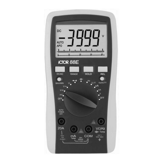
OVERVIEW The VC88E digital multimeter is a battery-driven 3-¾" digital multimeter. It uses an LCD with a 23 mm- high display for easy reading. The automatic overload protection feature makes operation more convenient. The digital multimeter has the function of measuring DCV, ACV, DCA, ACA, resistance, capacitance, frequency, temperature, both Fahrenheit and Celsius, duty cycle and diode and a continuity performance test. -
Page 3: Technical Features
TECHNICAL FEATURES 2-1. Accuracy: ± (a% × reading data + digits), environment temperature at (23°C±5), relative humidity less than 75%, 2-2. DC Voltage DCV Range Accuracy Resolution 400mV ±(1.5%+6) 0.1mV ±(0.5%+6) 10mV 400V 100mV 1000V ±(1.0%+4) Input impedance 400mV Range 10MΩ, other range is 40MΩ. 2-3. - Page 4 2-7. Capacitance C Range Accuracy Resolution 40nF ±(2.5%+6d) 10pF 400nF 100pF ±(3.5%+8d) 4µF 40µF 10nF 400µF ±(5.0%+8d) 100nF 2-8. Frequency F Range Accuracy Resolution 100Hz 0.1Hz 1000Hz 10kHz 10Hz ±(0.5%+4d) 100kHz 100Hz 1MHz 1kHz 30MHz 10kHz Input sensitivity:1.0V. 2-9. Diode and continuity performance test Range Value displayed Testing condition Forward DCA is approx.
-
Page 5: Operation
OPERATION 4-1. Panel description 1. LCD: displays the measuring value and unit. 2. Function key: 2-1. SELECT key: DC /AC mode, temperature C/F, Diode / Continuity performance switch. 2-2. RANGE key: select auto range or manual range mode. Auto range is the normal mode, it will display 'AUTO' symbol. Press it to change to manual range. - Page 6 Note: When measuring ACV under auto range mode, pressing the RANGE key will display AC mV range. 4. Connect the leads in parallel across the electric circuit under test, LCD displays voltage as measured by the test leads. Note: 1. Operator should first set the selector knob to the highest range, if operator has no idea about the range of voltage under test, then select the proper range based on displayed value.
- Page 7 1. The LCD displays 'OL' when the resistance is over the selected range. When measuring a value over 1MΩ, the reading will take a few seconds to become stable. This is normal for high resistance measuring. 2. When the input lead is in an open circuit, overload displays 'OL'. 3.
- Page 8 4-10. Continuity performance test: 1. Insert the black test lead into the 'COM' terminal and the red one into the 'V/Ω/Hz' terminal. 2. Turn the selector knob to range, press the SELECT key to select the continuity measurement mode. 3. Place the test leads onto two points of the tested circuit, if the inner buzzer sounds, the resistance is less than 50Ω.
- Page 9 Fault Solution Turn on the power No reading on LCD Set the HOLD key to a correct mode Replace battery signal appears Replace battery Large Error Value Replace battery These specifications are subject to change without notice. We hereby will not be responsible for any accident and damage caused by improper operation. The functions stated in this User Manual cannot be exceeded by special use.