Table of Contents
Advertisement
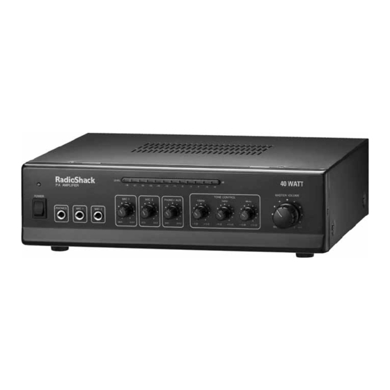
Thank you for purchasing your 40-Watt PA Amplifier from
RadioShack. It gives you the versatility and power you need in
a professional sound system. Your amplifier's wide frequency
response easily handles amplification of voice and music. Use it
in meeting halls and auditoriums, at sports events, in schools,
and in the office for paging systems—anywhere you need to
deliver special announcements with excellent sound.
What's Included
PA Amplifier
Fuse (Installed)
User's Guide
Please read this user's guide before installing, setting up, and
40-Watt
PA Amplifier
AC Power Cord
DC Power Cord
using your new amplifier.
www.radioshack.com
32-2054
Advertisement
Table of Contents

Related Manuals for Radio Shack 32-2054


Summary of Contents for Radio Shack 32-2054
- Page 1 What’s Included PA Amplifier AC Power Cord Fuse (Installed) DC Power Cord User’s Guide Please read this user’s guide before installing, setting up, and using your new amplifier. 40-Watt www.radioshack.com 32-2054...
-
Page 2: Table Of Contents
Contents Contents Quick Start ... 3 A Look at Your Amplifier... 6 Front View... 6 Rear View ... 7 Preparation... 8 Placing the Amplifier ... 8 Placing Speakers ... 8 Presetting the Controls... 8 Presetting the Audio Input Sources... 8 Presetting the Amplifier... -
Page 3: Quick Start
Quick Start Retaining Catch Press down the retaining catch of the correct terminal and insert the wire end into the terminal’s hole. Then, release the retaining catch to secure the wire. To speaker’s positive terminal To speaker’s negative terminal To use AC power, use the AC power cord to connect your amplifier’s AC IN jack to a standard wall outlet. -
Page 4: A Look At Your Amplifier
A Look at Your Amplifier A Look at Your Amplifier Front View POWER PHONO/AUX Volume Control Turn the amplifier Adjust the volume of the turntable on or off. or auxiliary sound source. Power Indicator LEVEL Indicator (in dB) Monitors and controls Lights when the amplifier is turned on. -
Page 5: Preparation
Preparation Preparation Placing the Amplifier Put your amplifier to a place with adequate ventilation. Do not put it on thick carpeting (which can restrict air flow) or near a heat source, such as a heat vent or radiator (which can cause overheating). Placing Speakers Speaker placement depends on your room’s size and arrangement. -
Page 6: Connections
Connections Connections Connecting Speaker Wires to the Amplifier 1. Use a wire stripper (not supplied) to remove about half inch of the insulation from the end of the speaker wire. 2. Using a wire connector (not supplied), twist the exposed wire to secure all the wire strands. -
Page 7: Connecting Four Speakers In Series And Parallel Combination
Connections Connecting Four Speakers in Series and Parallel Combination 1. Group the four speakers into two pairs (A and B, C and D). Connect each pair of speakers in series: A’s positive terminal to B’s negative terminal, C’s negative terminal to D’s positive terminal. If you use all 8 speakers, the total impedance of a pair is 16 . -
Page 8: Troubleshooting
Connections Transformer 8 , 2.5W Speaker Transformer Transformer 8 , 5W Speaker 16 , 1.25W Speaker Troubleshooting Problem Sound sources or speakers No power are not properly connected. The MASTER VOLUME, MIC 1, MIC 2, PHONO/AUX, Amplifier 100 Hz, 1 kHz, 8 kHz controls are set to minimum. -
Page 9: Specifications
Specifications Specifications Output Power (at THD 10%, 4 Load 1kHz)...40W Total Harmonic Distortion (at 5 Watts, 4 , 1kHz, with Band Pass Filter) MIC ... 0.50% AUX ... 0.10% PHONO ... 0.30% Input Sensitivity (at 10%, THD, 1kHz) MIC ...2.5 mV AUX ...150 mV PHONO ...3.5 mV Signal to Noise Ratio with A-WTD... -
Page 10: Do Stuff
Safety 17. An outside antenna system should not be located in the vicinity of overhead power lines or other electric light or power circuits, or where it can fall into such power lines or circuits. When installing an outside antenna system, extreme care should be taken to keep from touching such power lines or circuits as contact with them might be fatal. -
Page 11: Limited Warranty
RadioShack Customer Relations 300 RadioShack Circle, Fort Worth, TX 76102 Protect the environment by recycling used electronics. Go to www.ecyclingcentral.com ©2008. RadioShack Corporation. All rights reserved. RadioShack and RadioShack.com are trademarks used by RadioShack Corporation. 12/99 09A08 32-2054 Printed in China...