Table of Contents
Advertisement
FOR YOUR SAFETY
If you smell gas:
1. Open windows.
2. DO NOT try to light any appliance.
3. DO NOT use electrical switches.
4. DO NOT use any telephone in
your building.
5. Leave the building.
6. Immediately call your local gas
supplier after leaving the building.
Follow the gas supplier’s
instructions.
7. If you cannot reach your gas
supplier, call the Fire Department.
WARNING
Fire Hazard
Do not store or use petrol or other
flammable vapours and liquids in the
vicinity of this or any other appliance.
Some objects will catch fire or explode
when placed close to heater.
Failure to follow these instructions can
result in death, injury or property
damage.
WARNING
Improper installation, adjustment, alteration, service
or maintenance can result in death, injury or property
damage. Read the installation, operation and service
manual thoroughly before installing or servicing
this equipment.
Installation must be done by a registered installer/
contractor qualified in the installation and service
of gas-fired heating equipment or your gas supplier.
Quality in Any Language™
© Copyright 2004 Roberts-Gordon
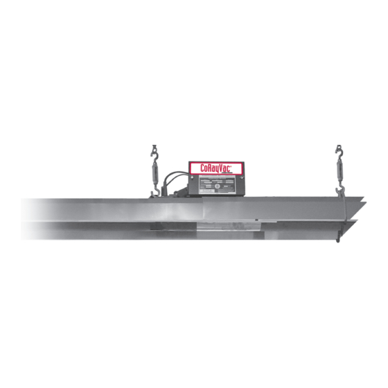
CoRayVac
Custom-Engineered,
Low-Intensity Infrared
Heating Systems
Installation, Operation &
Service Manual
Roberts-Gordon
Oxford Street
Bilston, West Midlands WV14 7EG UK
Telephone: +44(0) 1902 494425
Fax: +44(0) 1902 403200
Service Telephone: +44(0) 1902 498733
Service Fax: +44(0) 1902 401464
E-mail: uksales@rg-inc.com
E-mail: export@rg-inc.com
www.rg-inc.com
®
CRT-10
CRT-15
CRT-20
CRT-25
CRT-30
Installer
Owner
128100UK Rev. B 09/04
Advertisement
Table of Contents

Related Manuals for Roberts Gorden CRT-10

Summary of Contents for Roberts Gorden CRT-10
- Page 1 Fire Department. WARNING Heating Systems Installation, Operation & Service Manual Fire Hazard CRT-10 Do not store or use petrol or other CRT-15 flammable vapours and liquids in the vicinity of this or any other appliance. CRT-20 Some objects will catch fire or explode when placed close to heater.
-
Page 3: Table Of Contents
TABLE OF CONTENTS SECTION 1: Heater Safety ..........2 1.1 Manpower Requirements ........2 SECTION 2: Installer Responsibility ......2 2.1 Low Level User Instructions........2 2.2 Corrosive Chemicals...........3 2.3 National Standards and Applicable Codes ..3 SECTION 3: Critical Considerations......4 3.1 Required Clearances to Combustibles ....4 3.2 Clearance Data...........5 SECTION 4: Major Components ........7 4.1 Standard Parts List ..........9... - Page 5 TABLE OF FIGURES Figure 1: Standard Reflector ...........5 Figure 2: One Side Reflector ..........5 Figure 3: Two Side Reflectors .........5 Figure 4: 2-Foot Deco Grille..........6 Figure 5: Protective Grille and 1 Foot Deco Grille...6 Figure 6: Major Component Descriptions .......7 Figure 7: Major Component Descriptions (Continued)..8 Figure 8: Critical Hanger Placement ......10 ®...
- Page 7 Product Approval...
-
Page 8: Section 1: Heater Safety
® CORAYVAC NSTALLATION PERATION AND ERVICE ANUAL SECTION 1: HEATER SAFETY • To provide the owner with a copy of this installation, operation and service manual. Your Safety is Important to Us! This symbol is used throughout • To never use heater as support for ladder or the manual to notify you of possi- other access equipment and never hang or ble fire, electrical or burn hazards. -
Page 9: Corrosive Chemicals
SECTION 2: I NSTALLER ESPONSIBILITY 2.2 Corrosive Chemicals CAUTION Do not use heater in an area containing corrosive chemicals. Avoid the use of corrosive chemicals to ensure a longer life of the burner, tubing and other parts. Failure to follow these instructions can result in property damage. -
Page 10: Section 3: Critical Considerations
® CORAYVAC NSTALLATION PERATION AND ERVICE ANUAL SECTION 3: CRITICAL CONSIDERATIONS WARNING 3.1 Required Clearances to Combustibles Clearances are the required distances that combus- tible objects must be away from the heater to pre- vent serious fire hazards. Combustibles are materials, which may catch on fire and include com- mon items such as wood, paper, rubber, fabric, etc. -
Page 11: Clearance Data
2. Clearances B, C and D can be reduced by 50% after 7.5 m (25') of tubing downstream from where the burner and burner tube connect. 3. All measurements are in Millimeters. CLEARANCES TO COMBUSTIBLES Figure 1: STANDARD REFLECTOR Model CRT-10 1220 CRT-15 1220 CRT-20 1220... -
Page 12: Figure 4: 2-Foot Deco Grille
2. Clearances B, C and D can be reduced by 50% after 7.5 m (25') of tubing downstream from where the burner and burner tube connect. 3. All measurements are in Millimeters. CLEARANCES TO COMBUSTIBLES Figure 4: 2-FOOT DECO GRILLE Model CRT-10 1220 CRT-15 1220 CRT-20 1220... -
Page 13: Section 4: Major Components
SECTION 4: M AJOR OMPONENTS SECTION 4: MAJOR COMPONENTS Optional reflector configurations are shown on Page 5, Figure 1 through Page 6, Figure 5. Install appro- The figures in this section provide a general over- priate suspension hardware, beam clamps, chain or ®... -
Page 14: Figure 7: Major Component Descriptions (Continued)
® CORAYVAC NSTALLATION PERATION AND ERVICE ANUAL Figure 7: Major Component Descriptions (Continued) ROBERTS GORDON ® BZC 700 Controller ROBERTS GORDON ® BZC 300 RG-30 and RG-45 Pump Controller ROBERTS GORDON ® BZC 100 Controller with Sensor Reflector End Cap (Aluminum or Stainless Steel) Remove center section to... -
Page 15: Standard Parts List
SECTION 4: M AJOR OMPONENTS 4.1 Standard Parts List Table 1: Contents of CORAYVAC ® Burner Carton 91107720 U Clip Package - 20 off Part No. Description Quantity 02750303 Aluminium Reflector E000XXXX CORAYVAC ® Burner (Rate and Fuel Varies) S5163W Stainless Steel Reflector E0007565 Accessory Package 02750304 Aluminium Reflector with Hole... -
Page 16: Section 5: Heater Installation
® CORAYVAC NSTALLATION PERATION AND ERVICE ANUAL SECTION 5: HEATER INSTALLATION Do not locate the gas or electric supply lines directly WARNING over the path of the flue products from the heater. Crush Hazard The heater must be installed in a location that it is readily accessible for servicing. -
Page 17: Figure 9: Corayvac Assembly Overview
SECTION 5: H EATER NSTALLATION Figure 9: CORAYVAC ® Assembly Overview... -
Page 18: Tube Installation
® CORAYVAC NSTALLATION PERATION AND ERVICE ANUAL Step 5.1 Tube Installation NOTE: Description Part Number Tube 91409XXX Turnbuckle 91903201 Tube/Reflector Hanger 03090100 Step 5.2 Coupling and Tube Assembly Close Coupling with tab Start Slide Bar/Coupling Lock onto Coupling Open Closed Insert Tubes into Coupling Tighten Coupling to join Tubes Description... -
Page 19: Reflector Installation
SECTION 5: H EATER NSTALLATION Step 5.2.1 Coupling and Tube Assembly (Continued) Tighten Slide Bar as shown below. Correct slidebar dimensions Incorrect Slide Bar position Repeat Step 5.2 on Page 12, A - D until all tubes are assembled. NOTE: If Coupling is not tight, loss of vacuum can occur. Step 5.3 Reflector Installation Step 5.3.1 Reflector Installation with Hole Description... - Page 20 ® CORAYVAC NSTALLATION PERATION AND ERVICE ANUAL Step 5.3.2 Reflector Installationg Description Part Number Reflector Support Package 03050010 Wire Form 91908004 Reflector Support Strap 03050000 Screw #8 x 3/4 94320812 U-Clip Package 91107720 NOTE: Minimum reflector overlap must be 180 mm. Reflector End Cap 027508XX...
- Page 21 SECTION 5: H EATER NSTALLATION Step 5.3.3 Reflector, U-Clip and Reflector Support Installation The pictorial drawings of the heater construction in supports are used. The positioning of reflector supports Section 5 are schematic only and provide a general and U-clips depend on the individual installation. Use guideline of where hangers, reflector supports and either pop rivets or sheet metal screws instead of U-clips U-clips are to be installed.
-
Page 22: Burner Installation
® CORAYVAC NSTALLATION PERATION AND ERVICE ANUAL Step 5.4 Burner Installation NOTE: Description Part Number Bolt E0007588 Burner E000XXXX Lock Washer 96411600 Gasket 01367800 End Vent E00094XX... -
Page 23: Section 6: Optional Heater Accessories
SECTION 6: O PTIONAL EATER CCESSORIES SECTION 6: OPTIONAL HEATER ACCESSORIES 6.1 Elbow Configuration Step 6.1.1 Elbow Installation Tube Coupling Elbow Description Part Number 90° Elbow 01335801 Coupling and Lock 01312700 Step 6.1.2 Elbow Installation Tube Coupling Step 6.1.3 Tee Installation Description Part Number 01330XXX... -
Page 24: Reflector Side Extension
® CORAYVAC NSTALLATION PERATION AND ERVICE ANUAL 6.2 Reflector Side Extension Step 6.2.1 Bracket Installation Description Part Number Reflector Side Extension Package S7377K Reflector Side Extension 01368000 Retainer Clips 02751200 Sheet Metal Screws 94118106 Order Separately Reflector Side Extension Bracket 01329910 Step 6.2.2 Side Reflector Installation 8 x 3/8 (3. -
Page 25: One Foot Decorative Grille
SECTION 6: O PTIONAL EATER CCESSORIES Step 6.3 One Foot Decorative Grille Step 6.3.1 Decorative Grille Bracket (One Foot Grille) Description Part Number Bracket 01363003 Step 6.3.2 One Foot Decorative Grille Description Part Number Decorative Grille 2440mm x 305mm 91406700 Step 6.3.3 Joint Piece and Reinforcement (One Foot Grille) Description Part Number... - Page 26 ® CORAYVAC NSTALLATION PERATION AND ERVICE ANUAL Step 6.3.4 End Piece and Reflector End Cap (One Foot Grille) Description Part Number End Piece 01365901...
-
Page 27: Protective Grille Installation
SECTION 6: O PTIONAL EATER CCESSORIES 6.4 Protective Grille Installation Step 6.4.1 Silicone Cap Installation Silicone Cap Grille Finger Description Part Number Grille Section 08050001 Grille End Cap 08050002 Silicone Cap 91915951-6P Step 6.4.2 Grille End Cap Installation Grille Grille End Cap Bend up Pull outward Step 6.4.3 Grille Installation... -
Page 28: Sports Hall Guard Installation
® CORAYVAC NSTALLATION PERATION AND ERVICE ANUAL 6.5 Sports Hall Guard Installation Step 6.5.1 Grille Installation Description Part Number Mesh Guard 2438 mm E0009855 Mesh Guard 1524 mm C2329B Strap Stainless Steel S5218W Step 6.5.2 Fastener Installation Description Part Number Nut Spire C1088B Screw #8 x 3/8 (3.9 x 9.5 mm) -
Page 29: Sports Hall Filter
SECTION 6: O PTIONAL EATER CCESSORIES 6.6 Sports Hall Filter Step 6.6.1 Remove Standard Door Step 6.6.2 Install New Door Filter... -
Page 30: Section 7: Pump Installation And Venting
® CORAYVAC NSTALLATION PERATION AND ERVICE ANUAL SECTION 7: PUMP INSTALLATION AND VENTING 7.1 Mounting Wall Bracket Assembly 7.1.1 Mounting Platform WARNING The standard method of mounting the RG-30 and RG-45 pump is on an outside wall and venting directly through the wall or roof. Crush Hazard The pump may be mounted by using mounting Mount pump with materials... -
Page 31: Figure 12: Pressure Switch Installation
SECTION 7: P NSTALLATION AND ENTING 7.1.2 Attaching Pressure Switch 7.1.3 Flue Installation Drill two holes in the fan base housing to accept the The fan outlet must always discharge horizontally. pressure switch mounting bracket and attach the Mount the 150 mm (6") pump boot to the pump out- switch by means of 2 self-tapping screws. -
Page 32: Building Ventilation
® CORAYVAC NSTALLATION PERATION AND ERVICE ANUAL 7.1.4 Pump Inlet Adapter for 100 mm (4") Tubing 7.1.5 Pump Inlet for 6" (15 cm) Tubing Apply a bead of silicone sealant 316° C to the 150 Attach 150 mm (6") pump boot to the inlet See Fig- mm (6") inside of the reducer (150 mm x 100 mm) ure 15, then See Section 7.1.3. -
Page 33: Condensate Drain Assembly
SECTION 7: P NSTALLATION AND ENTING 7.3 Condensate Drain Assembly The condensate drain assembly is composed of a The condensate drain assembly in the pump tee, draincap, and a non return valve. discharge line can be eliminated if the discharge line is horizontal through the wall and pitched down at A condensate drain assembly must be installed on the least 6 mm per 3 m (1/4"... -
Page 34: Acoustic Enclosure (Optional)
® CORAYVAC NSTALLATION PERATION AND ERVICE ANUAL Figure 17: Condensate Drain Assembly - Vertical Flue Description Part Number Tee 150 mm (6") 01330204 Drain Cap 150 mm (6") 02718852 7.4 Acoustic Enclosure (Optional) The acoustic enclosure is used to reduce noise from inside the junction box. -
Page 35: Figure 19: Acoustic Enclosure
SECTION 7: P NSTALLATION AND ENTING Figure 19: Acoustic Enclosure Junction Box (wiring diagram inside) Flue Tailpipe Discharge Connection Figure 20: Junction Box Wiring Diagrams 3 Ø Motors 1 Ø Motors 7.4.1 Noise Data All noise data has been determined according to EN ISO 3746:1995, survey method "Parallelepiped measurement surface". -
Page 36: Section 8: Outside Air Supply
® CORAYVAC NSTALLATION PERATION AND ERVICE ANUAL SECTION 8: OUTSIDE AIR SUPPLY IMPORTANT: If the building has a slight negative pressure or contaminants are present in the air, an The CORAYVAC ® system is approved for use with outside combustion air supply to the heaters is an outside air system. -
Page 37: Section 9: Gas Piping
SECTION 9: G IPING SECTION 9: GAS PIPING WARNING Installation pipes should be fitted in accordance with National Standards. Pipe work from the meter to the heater(s) must be of adequate size. Pipes of smaller size than the heater inlet gas connection should not be used. -
Page 38: Section 10: Wiring
® CORAYVAC NSTALLATION PERATION AND ERVICE ANUAL SECTION 10: WIRING via a locally mounted double pole fused switch hav- ing a minimum disconnection of 3 mm on each pole. WARNING The burner is fused at 1 A. There are no control con- nections in the standard burner. -
Page 39: Figure 25: Crt Burner Internal Wiring
SECTION 10: W IRING Figure 25: CRT Burner Internal Wiring If any of the original wire as supplied with the heater must be replaced, it must be replaced with wiring material having a temperature rating of at least 105° C and 600 V. -
Page 40: Section 11: Operation And Maintenance
® CORAYVAC NSTALLATION PERATION AND ERVICE ANUAL SECTION 11: OPERATION AND MAINTENANCE Figure 26: CORAYVAC ® System Sequence of Operation Chart KEY TO SYMBOLS Thermostat Pressure Switch Pump Operating Power to Burners 30 sec approx. 2 minute Loss of Pressure post purge Switch Signal Figure 27: Burner Sequence of Operation Chart... -
Page 41: Commissioning And Testing
SECTION 11: O PERATION AND AINTENANCE Power to the burner sequence controller initiates an reach full temperature (approximately 30 minutes). approximate 45 second purge period. Following the Set the dampers at each branch to achieve the set- purge period, the solenoid valve opens. This allows tings for the installed burner model as listed in the vacuum, created in the tube to lift the diaphragm 11.2.11. -
Page 42: Section 12: Servicing Instructions
® CORAYVAC NSTALLATION PERATION AND ERVICE ANUAL SECTION 12: SERVICING INSTRUCTIONS IMPORTANT: Never use the heater as a support for 12.2 Component Removal ladders or other access equipment. Always test for First, isolate the heater from the gas and electricity gas soundness with a suitable detection fluid after supply;... -
Page 43: Maintenance Checklist
SECTION 12: S ERVICING NSTRUCTIONS 12.3 Maintenance Checklist Installation, Service and Annual Inspection of the heater must be done by a contractor qualified in the installation and service of gas-fired heating equipment. Read this manual carefully before installation, operation, or service of this equipment. - Page 44 ® CORAYVAC NSTALLATION PERATION AND ERVICE ANUAL Electrode Replace if there are cracked ceramics, excessive carbon residue, or erosion of the electrode. The electrode gap should be 1/8” (3 mm). Thermostat There should be no exposed wire or damage to the thermostat. Suspension Points Make sure the heater is hanging securely.
-
Page 45: Section 13: Troubleshooting
SECTION 13: T ROUBLESHOOTING SECTION 13: TROUBLESHOOTING 13.1 Troubleshooting Flow Chart... - Page 46 ® CORAYVAC NSTALLATION PERATION AND ERVICE ANUAL Troubleshooting Flow Chart...
-
Page 47: Figure 28: Vacuum Reading
SECTION 13: T ROUBLESHOOTING Figure 28: Vacuum Reading... -
Page 48: Section 14: Replacement Parts
® CORAYVAC NSTALLATION PERATION AND ERVICE ANUAL SECTION 14: REPLACEMENT PARTS Use only genuine ROBERTS GORDON ® replacement parts. Use of parts not specified by Roberts-Gordon voids warranty. Failure to follow these instructions can result in property damage. Item Description Part Number Item Description Part Number Ignition Module... -
Page 49: Section 15: Specifications
SECTION 15: S PECIFICATIONS SECTION 15: SPECIFICATIONS 15.1 Material Specifications 15.3 Venting Specifications 15.1.1 Combustion and Tubes 15.3.1 Pumps 100 mm dia 16 gauge heat treated aluminised mild RG-30-1 Ø RG-30-3 Ø steel. RG-45-1 Ø RG-45-3 Ø 15.1.2 Reflectors Consult the manufacturer for availability of alternate NS3 H14 aluminium or 1.4016 2R stainless pumps. -
Page 50: Burner Specifications
® CORAYVAC NSTALLATION PERATION AND ERVICE ANUAL 15.7 Burner Specifications General Specifications for CORAYVAC ® heaters are as follows: *See Page 4, Section 3 for clearances to combustibles. BURNER COMPONENTS Orifice Size End Vent Air Shutter Plate 3.0 mm 2.4 mm CRT 10 #35 (black) (fluor yellow) -
Page 51: Pump Dimensions And Specifications
SECTION 15: S PECIFICATIONS 15.8 Pump Dimensions and Specifications Pump Dimensional Data (mm) Model RG30-1 RG30-3 RG45-1 RG45-3 Pump Specifications Model RG30-1 RG45-1 RG30-3 RG45-3 Part No. 90710108 90710109 90710111 90710112 Weight (kg) 41.5 43.5 41.5 43.5 Power (W) 1100 1100 Run Current (A) 3.25... - Page 52 ® CORAYVAC NSTALLATION PERATION AND ERVICE ANUAL...
- Page 54 Attach this information to a wall near the ROBERTS GORDON heater. ® I n f r a r e d H e a t i n g Read the Installation, Operation, and Service Manual thoroughly before installation, operation, or service. WARNING OPERATING INSTRUCTIONS TO TURN OFF THE HEATER...