
Related Manuals for ESI ESRTD5


Summary of Contents for ESI ESRTD5
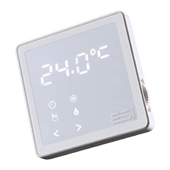
- Page 1 ESRTD5 & ESRTD5VF Digital Room Thermostat with TPI & Delayed Start Installation Instructions...
- Page 2 Thank you for choosing ESi Controls. All our products are tested in the UK so we are confident this product will reach you in perfect condition and give you many years of service. However, for additional peace of mind, we recommend you register your product online at www.esicontrols.co.uk/warranty for your...
-
Page 3: Table Of Contents
Contents Installation Instructions 1. Technical Data 2. Installation Installation Safety Instructions General Safety Instructions Warning Notices Maintenance Fitting the Room Thermostat Installing the Room Thermostat Wiring Diagram DIP Switch Settings... -
Page 5: Installation Instructions
Installation Instructions... -
Page 6: Technical Data
1. Technical data Thermostat Features Battery Models Mains Models Hard-wired Hard-wired Hard-wired, built-in sensor ESRTD5VF ESRTD5 Wireless, built-in sensor complete with receiver Temperature Control Class ErP Class 4 (2%) Energy Efficiency TPI (Chrono Proportional) Control, Technology Delayed Start, Optimum Start,... -
Page 7: Installation
2. Installation Installation Safety Instructions The unit must be installed by a suitably qualified person in accordance with the latest IEE Wiring Regulations. Isolate mains supply before commencing installation. Please read all instructions before proceeding. Ensure that the fixed wiring connections to the mains supply is via a fuse rated at not more than 3 Amps and Class ‘A’... -
Page 8: Warning Notices
Warning Notices WARNING: Always isolate the AC mains supply before installing. This product must be fitted by a competent person, and installation must comply with the guidance provided in the current editions of BS767 (IEE wiring regulations) and part “P” of the building regulations. Maintenance Always isolate the mains supply before commencing any work, servicing or maintenance on the system. -
Page 9: Installing The Room Thermostat
Installing the Room Thermostat 1. Use a flat headed screwdriver to press the fastener at the top of the unit, then gently loosen from the unit, unhooking from top to bottom. 2. Fix the 35mm back box, terminals at the top, onto a 2 flange metal back box with 2 BM3.5x23 screws. -
Page 10: Wiring Diagram
6. Ensure an appropriate fuse is fitted to the circuit before reconnecting to the mains supply. Wiring Diagram 6mm MAX N/C N/O ESRTD5 1 L : Live 2 N : Neutral 4 NC (OFF): Normally Closed 5 NO (ON): Normally Open N.B. -
Page 11: Dip Switch Settings
DIP Switch Settings - Heating HEAT COMP DELAY (TPI) OFF COMP DELAY (TPI) ON 6 CYCLES 3 CYCLES DELAYED START OFF DELAYED START ON Option to switch to: 1. Chronoproportional (Chrono) 2. 3 or 6 Cycles (Chrono on, only) 3. Delayed Start We are continuously developing our products to bring you the very latest in energy saving technology and simplicity. - Page 12 WARNING: Interference with sealed parts renders the guarantee void. In the interests of continuous product improvement we reserve the right to alter designs, specifications and materials without prior notice and cannot accept liability for errors. Version 6.10.1...