Table of Contents
Advertisement
Quick Links
Advertisement
Table of Contents

Related Manuals for Q-See QSD371614C4-250


Summary of Contents for Q-See QSD371614C4-250
- Page 1 QSD371614C4-250 User’s Manual Contact US: Q-See Products 8015 E. Crystal Dr Anaheim, CA 92807 Website: http://www.q-see.com Customer Service: Phone:877-998-3440 Email:cs@dpsi-usa.com Tech Support: Phone:877-998-3440 Email:ts@dpsi-usa.com 714-998-3509 Rev 042009 Fax:...
-
Page 2: Table Of Contents
1. INTRODUCTION ... 2 2. DVR FEATURES ... 2 3. PHYSICAL UNIT ... 3 3.1 Front Panel ... 3 3.2 Rear Panel ... 3 3.3 Remote Control ... 4 4. GETTING STARTED ... 5 5. HARDWARE SETUP ... 6 5.1 Hard Drive Installation ... 6 5.2 Monitor Connection ... - Page 3 11.1 QSD371614 4CH DVR series - compatible USB Flash Drives..29 11.2 Specifications ... 30 11.3 System Connection Diagram ... 31 11.4 DVR Accessories (included) ... 31 11.5 Q-SEE Product Warranty ... 32 Customer Information Card ... 32 Operation Manual-4CH Duplex DVR...
-
Page 4: Introduction
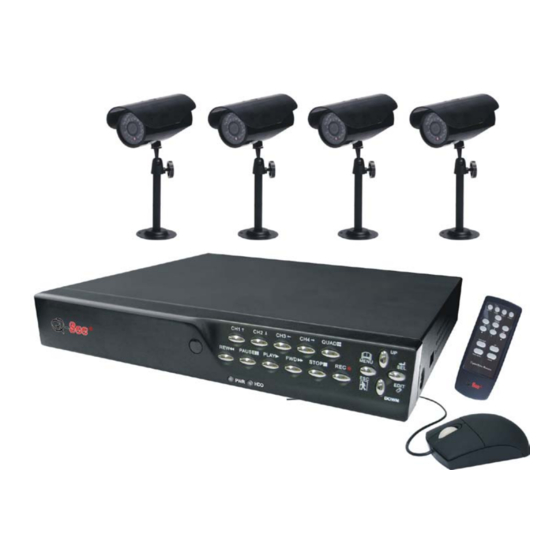
1. INTRODUCTION The QSD371614C4-250 system provides a total 4-channel digital video security surveillance system supporting duplex (simultaneous playback and record) functionality. You can use front panel buttons, remote control unit or mouse to operate all DVR menu settings. The functionality of each access option is exactly the same. -
Page 5: Physical Unit
Operation Manual-4CH Duplex DVR 3. PHYSICAL UNIT 3.1 Front Panel ● IR Remote Receiver ● LED Light (a) GREEN (PWR): The DVR unit is powered up and running. (b) RED (HDD): System is in Recording Mode or in Playback Mode. Some DVR is provided with touch-tone front panels. -
Page 6: Remote Control
[Input: AC 100-240V, 50/60Hz, 1.5A / Output: DC +12V == 3A] ● PS/2 MOUSE PORT Use this port for PS/2 mouse connection. If you have USB port mouse, use USB - PS/2 adapter to connect with this port. ● Fan 3.3 Remote Control The buttons on the DVR remote control unit operates the system’s basic functions, such as recording, playback, fast-forward, reverse, etc. -
Page 7: Getting Started
Operation Manual-4CH Duplex DVR ⑺ ■ (STOP) To stop playback, press the “STOP” button. ⑻ ► (PLAY) After recording, press “PLAY” button to start video playback. Playback will start with the oldest unread video data and then continue playing. ⑼ ► ► (FWD) This is the fast forward button. -
Page 8: Hardware Setup
If you are using a Mouse it must be connected to DVR before you startup system. Connect the power adapter to the DVR this will turn on the DVR. Make sure that a hard drive and camera(s) are properly installed. Start TV Monitoring and Recording. -
Page 9: Camera Connection
Operation Manual-4CH Duplex DVR Connect “VIDEO IN” of the monitor to “VIDEO OUT” of the DVR system using the BNC to RCA cable that comes with the DVR. 5.3 Camera Connection Connect the included video cables to the “VIDEO IN” of your DVR and “VIDEO OUT” of the camera with video cable and plug in the camera’s power adapter to the power feed of the video cable near the DVR. -
Page 10: Dvr Power Connection
5.5 DVR Power Connection Connect the DVR power adapter to the adapter jack at the rear panel of the DVR unit. It will boot up the system. If users install a new hard drive, it will ask you to format the hard drive before the system starts to run (Below Fig). - Page 11 operate live video display and image playback, or modify some parameter values that are independent of recording. If user does not have the right to modify the parameter value, there will be an identifier “ A: Mouse Control After system boot-up, hold the right mouse button and the login window will open. Hold the left mouse button to select the “Account”, and input correct account.
-
Page 12: Camera
Logout Channel auto sequence. The iron “ “OFF”. Move the mouse up or down to move the cursor. Click a left mouse button to change the settings. Click a right mouse button to go back to the previous. Hold the left mouse button to click the icon “ monitor (Fig (b)). -
Page 13: Record
option you can change the name of each channel if you want to. 6.2 Record Operation Manual-4CH Duplex DVR Use this option to enable recording on the channel (1,2,3,4). Only selected channels will be recorded no matter how many camera channels are displayed on the screen. - Page 14 Operation Manual-4CH Duplex DVR which means the system will record 48 frames per second with all channels. User can set frame rate as 3~25 frames per second with each channel. The max value of total frames per second with all channels is 50 frames. For NTSC video output format, system default value is 15 frames per second with each channel, which means the system will record 60 frames per second with all channels.
-
Page 15: Alarm
- Red bar: The time period with a red bar will continuously record (Time record) unless you manually stop recording during that time. - Green bar: The system will record whenever motion is detected. (See the following chapter “MOTION DETECTION”) 6.3 Alarm will sound continuously. - Page 16 C: [MOTION DETECTION] [CHANNEL] Values are “1, 2, 3, 4, Off”. The maximum sensitivity level is 4. [MOTION AREA] Use this option to select the size of the area that you want to be sensitive to motion. Use the keypad button, remote control button or mouse to assign the area. The keypad and mouse control instructions are below.
-
Page 17: Screen
Operation Manual-4CH Duplex DVR 6.4 Screen [BORDER] User can make the white borderline around each channel appear or disappear by setting this option to “on” or “off”. [AUTO SEQUENCE] This option is used to setup the channels to appear one at a time on the screen in automatic sequence, and select the time that each channel appears on the screen before switching to the next channel. -
Page 18: Hard Drive Setup
In this menu, you can see the information of the hard drive installed in the DVR, change the system password, adjust keypad tone, access browser event list or adjust current time on the system. If user logs into the system at admin level, the menu bar will be displayed as user can enter into the “account”... -
Page 19: Account Setup
password is “111111”. Type the password and press any key button. When HDD is formatting, and has successfully formatted, you will see the message below blinking. If the password is incorrect, you will see the below message blinking. Then try to enter the right password again. -
Page 20: Password Setup
Move the cursor to change the highlighted option to Level, and then press [SEL] to adjust user level (operator/guest). 6.5.3 Password Setup Button function on the front panel or remote control: Use CH1 for up, CH2 for down, CH3 for left, CH4 for right. Use the same operation procedure to input new password and confirm password. -
Page 21: Keypad Tone
you choose OFF, the account information will be kept when you logout of the system. 6.5.5 Keypad Tone Set the keypad tone to “ON” or “OFF” to enable or disable keypad tone during operation. 6.5.6 Time Set You can adjust the current time, date and year at any time by region. Set your region first and set the current time so that the video back-up data can be played with the correct time panel or remote control and then press “SELECT”... -
Page 22: Firmware Upgrade
previous event according to input time period if the data hasn’t been over-written. To playback by Event list, using [UP]/[DOWN] or channel number (CH3 for Page Up or CH4 for Page Down) key on the front panel or remote control, select the event that you want to playback and press “PLAY”... -
Page 23: Exit
6.8 Exit After you change settings on DVR menu, you need to confirm the changes under the EXIT menu. [EXIT & SAVE CHANGE] Save change and go back to main screen. [EXIT & DISCARD CHANGES] No change and go back to main screen. [LOAD SETUP DEFAULT] Load default settings. -
Page 24: Backup Via Usb Flash Drive
Operation Manual-4CH Duplex DVR to change the value of the playback date and start time, then press the right mouse button. Then use the left mouse button to click “Search”, the playback will start from the date & time selected by the user. 8. -
Page 25: Recording Length
It will take a few minutes to copy the video data onto a USB flash drive. The file size number is going up until it’s done while displaying the messages below: WRITING… Then it will show the following message on the screen: FIXATING…... -
Page 26: Program Interface
Operation Manual-4CH Duplex DVR Select setup option. Set up the install directory. Execute: Start >Program> Vx4SLPlayer. 10.2 Program Interface Double click icon “ ” on desktop to run the program. 10.3 Button Functions... - Page 27 1) Click “ ” to play the video recorder in “*.VVF” format. 2) Still Capture Click “ ” to capture single frame. Click the right mouse button to select “Options…” to 1. Open File 1. Open File 3. Rewind 3. Rewind 5.
- Page 28 setup path to save image. Click the left mouse button to select folder that you want to save to, for example select the folder as “E:\VOC 4CH\backup”. 3) In “Options” window, you can setup other menu selections such as “General & On screen display date/time format”.
- Page 29 audio option is not available. Next click “ “ ” to select video compression mode. Finally click “ progress will be showed as a percentage. Notes: 1. When selecting video compression mode, user should test the compression that he selects to see if it is matching his computer. If it doesn’t match the computer may not be able to play the file.
- Page 30 Operation Manual-4CH Duplex DVR The “Output Size” is the size of output file. Left click “ ” to setup save path. Then left click “ ”.
-
Page 31: Appendix
11. APPENDIX 11.1 QSD371614 4CH DVR series - compatible USB Flash Drives. In case noise occurs on USB line due to a variety of reasons such as power noise, it might cause an error during the data transferring process. In this case, it requires re-transferring the date to the flash drive. -
Page 32: Specifications
11.2 Specifications ITEM Video Format Operation System Video Input Video Output Display Speed Recording Speed Compression Method Recording Mode Recording Time Hard Drive Capacity USB port PS/2 Mouse 38KHZ IR Remote Control Power Input Dimension (LxHxW) ITEM Image Sensor Horizontal Resolution Minimum Luminance Lens / Field of View Power Supply... -
Page 33: System Connection Diagram
Operation Manual-4CH Duplex DVR 11.3 System Connection Diagram Note: We STRONGLY recommend that you plug the DVR and cameras into a Transient Voltage Surge Protector (UL-1449 rating). Look for a clamping voltage of 330 or lower, Joule rating of at least 400, and a response time of 10 nanoseconds or less. -
Page 34: Q-See Product Warranty
11.5 Q-SEE Product Warranty Thank you for choosing our products. All of our products users have a conditional free warranty repair service for hardware within 12 months starting from purchase date, and a free exchange service within one month (valid for manufacturing defects). Permanent upgrading service is provided for the software. - Page 35 If you have questions: Mailing Address: DPS Inc. 8015 E. Crystal Dr Anaheim, CA 92807 Website: http://www.q-see.com Fax: 714-998-3509 Operation Manual-4CH Duplex DVR Contact Us: Customer Service: Phone: 877-998-3440 x 538 Email: cs@dpsi-usa.com Tech Support: Phone: 877-998-3440 x 539 Email: ts@dpsi-usa.com...