
Related Manuals for Ingersoll-Rand SSR UP6 15


Summary of Contents for Ingersoll-Rand SSR UP6 15
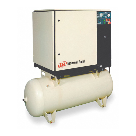
- Page 1 SSR UP6 15, UP6 20, UP6 25, UP6 30 60Hz OPERATION AND MAINTENANCE MANUAL This manual contains important safety information and must be made available to personnel who operate and maintain this machine. C.C.N. : 22083729 REV. : C DATE : JANUARY 2005...
- Page 2 AIR COMPRESSOR GROUP BONDED WARRANTY & REGISTERED START UP Warranty The Company warrants that the equipment manufactured by it and delivered hereunder will be free of defects in material and workmanship for a period of twelve months from the date of placing the Equipment in operation or eighteen months from the date of shipment from the factory, whichever shall first occur.
-
Page 3: Table Of Contents
Open drip proof (motor) OPERATING INSTRUCTIONS Czech MAINTENANCE Danish German Greek TROUBLE SHOOTING English Spanish Estonian Finnish French Hungarian Italian Lithuanian Latvian, Lettish Maltese Dutch Norwegian Polish Portuguese Slovak Slovenian Swedish Chinese http://air.irco.com SSR UP6 15, UP6 20, UP6 25, UP6 30... -
Page 4: Foreword
English version. improvements to products without notice and without incurring any obligation to make such changes or add such improvements to products sold previously. © COPYRIGHT 2005 INGERSOLL–RAND COMPANY http://air.irco.com SSR UP6 15, UP6 20, UP6 25, UP6 30... -
Page 5: Decals
Do not use fork lift truck from this side. Emergency stop. On (power). Off (power). AUTOMATIC RESTART MAINTENANCE MAINTENANCE PROHIBITED FRAGILE KEEP DRY THIS WAY UP USE NO HOOKS NO SIDE CLAMPS HOURS http://air.irco.com SSR UP6 15, UP6 20, UP6 25, UP6 30... - Page 6 Use ULTRA–Plus Coolant only POWER INSPECT Failure to use the specified coolant may result in damage to the machine Every X months, if sooner than required by CHANGE / REPLACE CLEAN operating hours http://air.irco.com SSR UP6 15, UP6 20, UP6 25, UP6 30...
- Page 7 Can cause severe injury or death. Do not operate without guard in place. Disconnect power before servicing. Lockout/Tagout machine. Air flow exhaust may contain flying debris. Safety protection should be worn at all times. http://air.irco.com SSR UP6 15, UP6 20, UP6 25, UP6 30...
- Page 8 Decal, dual voltage (if needed) 32342669 Decal, starter box – 32017469 Decal, voltage 120/1/60 54499306 Decal, Ingersoll–Rand signature horizontal 20“ 32343063 Decal, maintenance parts † Optional position 30286686 Decal, notice rotation http://air.irco.com SSR UP6 15, UP6 20, UP6 25, UP6 30...
- Page 9 Decal, warning high pressure 22115703 Tag, rotation 60Hz 32343535 Decal, warning moving belts 32344095 Tag, shipping bracket 32343550 Decal, warning exposed fan 32343568 Decal, warning hazardous voltage † Optional position http://air.irco.com SSR UP6 15, UP6 20, UP6 25, UP6 30...
- Page 10 Do not use extinguishers intended for Class A or Class B fires on must have safe working pressure ratings of at least the machine rated electrical fires. Use only extinguishers suitable for class BC or class pressure. ABC fires. http://air.irco.com SSR UP6 15, UP6 20, UP6 25, UP6 30...
-
Page 11: Safety
Ingersoll–Rand and its associated distributors are happy to advise and assist in these matters. For further information, consult Material Data Sheets CPN 88303979 for ULTRA–Plus Coolant. http://air.irco.com SSR UP6 15, UP6 20, UP6 25, UP6 30... - Page 12 Unit will not restart automaticlly after power outage. (wye / star) Circuit shown in normal position de–energized. Valve, solenoid (Load) N.C. Valve, solenoid (Blowdown) N.O. All wiring to be in accordance with local codes. http://air.irco.com SSR UP6 15, UP6 20, UP6 25, UP6 30...
-
Page 13: General Information
Unit will not restart automaticlly after power outage. Valve, solenoid (Load) N.C. Valve, solenoid (Blowdown) N.O. Circuit shown in normal position de–energized. Relay, time delay (6 min) All wiring to be in accordance with local codes. http://air.irco.com SSR UP6 15, UP6 20, UP6 25, UP6 30... -
Page 14: Installation / Handling
Starter box 4 slots 15 (0.6) x 25 (1.0) Cooling air exhaust 1.00” NPT air discharge Customer power inlet See notes – Page 15 http://air.irco.com SSR UP6 15, UP6 20, UP6 25, UP6 30... - Page 15 Starter box 0.25 inch condensate drain Cooling air exhaust 4 slots 17 (0.7) x 44 (1.8) 1.00” NPT air discharge Customer power inlet Fork lift openings See notes – Page 15 http://air.irco.com SSR UP6 15, UP6 20, UP6 25, UP6 30...
- Page 16 Starter box 0.25 inch condensate drain Cooling air exhaust 4 slots 17 (0.7) x 44 (1.8) 1.00” NPT air discharge Customer power inlet Fork lift openings See notes – Page 15 http://air.irco.com SSR UP6 15, UP6 20, UP6 25, UP6 30...
- Page 17 Loosen, remove and discard 10mm shipping bolt. For belt the information on the compressor data plate and national and local tensioning procedure refer to Maintenance section. electrical codes. http://air.irco.com SSR UP6 15, UP6 20, UP6 25, UP6 30...
- Page 18 It is a requirement for air dryers covered under Aircare that correctly individual air lines. sized Ingersoll–Rand pre and afterfilters are installed. http://air.irco.com SSR UP6 15, UP6 20, UP6 25, UP6 30...
-
Page 19: Odp
There is a decal fitted to the starter door describing the procedure to change the connections for the alternative voltage Rewiring should only be effected by a competent Electrician. http://air.irco.com SSR UP6 15, UP6 20, UP6 25, UP6 30... - Page 20 There is a decal fitted to the starter door describing the procedure to change the connections for the alternative voltage Rewiring should only be effected by a competent Electrician. http://air.irco.com SSR UP6 15, UP6 20, UP6 25, UP6 30...
- Page 21 3–5 Sec ( 7–10 Sec) Starts per hour (maximum) ELECTRICAL DATA DOL / Star Delta Control voltage 120VAC Minimum fuse rating 125A 100A See note 1 Minimum wire size AWG See note 2 http://air.irco.com SSR UP6 15, UP6 20, UP6 25, UP6 30...
- Page 22 An independent electrical isolator or disconnect should be installed Ensure that the motor rotates in the correct direction as adjacent to the compressor. indicated by direction arrows, and on drawing. http://air.irco.com SSR UP6 15, UP6 20, UP6 25, UP6 30...
-
Page 23: Operating Instructions
CAUTION This unit is not designed or intended to operate when contaminated with silicone. Lubricants, greases or other items containing silicone should not be used on this unit. http://air.irco.com SSR UP6 15, UP6 20, UP6 25, UP6 30... - Page 24 4. Connector 13.Adaptor 5. Combination block 14.Intake valve assembly 6. Elbow 7. Tee, male run NOTES: 8. Reducer bushing A. Tubing 3/8 inch 9. Valve, solenoid (Blowdown) B. Tubing 1/4 inch http://air.irco.com SSR UP6 15, UP6 20, UP6 25, UP6 30...
-
Page 25: Controls
7. FAULT / HIGH AIR TEMPERATURE ALARM (Red) Turn off electrical Isolator or disconnect. Investigate cause of fault. 8. RESET BUTTON Press button to reset the control system following compressor trip. http://air.irco.com SSR UP6 15, UP6 20, UP6 25, UP6 30... - Page 26 2. Press EMERGENCY STOP button (3) and the compressor will stop immediately . 3. Turn off electrical isolator or disconnect. CAUTION After shutdown never allow unit to stand idle with pressure in receiver/separator system. http://air.irco.com SSR UP6 15, UP6 20, UP6 25, UP6 30...
- Page 27 Remove the cover plate and any necessary running with safety protection devices disabled or removed. local or national fittings. Clean the interior thoroughly and legislation. inspect all internal surfaces. http://air.irco.com SSR UP6 15, UP6 20, UP6 25, UP6 30...
- Page 28 3. Slowly remove fill/vent cap. 4. Remove plug from drain valve. 5. Open the drain valve and drain coolant into container. 6. Close the drain valve. 7. Replace plug in drain valve. http://air.irco.com SSR UP6 15, UP6 20, UP6 25, UP6 30...
-
Page 29: Maintenance
6. Apply a small amount of lubricant to the cartridge seal. 2. Remove the top cover to obtain access to the cooler. 3. Clean the cooler. 4. Rebuild in reverse order. http://air.irco.com SSR UP6 15, UP6 20, UP6 25, UP6 30... - Page 30 Turn the adjuster anti–clockwise to increase the set point or clockwise to decrease it. NOTE The pressure switch scale is a guide only. Use the machine pressure gauge to verify the upper and lower set points. http://air.irco.com SSR UP6 15, UP6 20, UP6 25, UP6 30...
- Page 31 9. Spin the drive to check alignment of the belt ribs on the pulleys (sheaves). A. Gas strut. B. Support bracket (part of pivoted assembly). C. Tension cam. http://air.irco.com SSR UP6 15, UP6 20, UP6 25, UP6 30...
- Page 32 Adjustments may be made depending on mny factors, including humidity and duty cycle. http://air.irco.com SSR UP6 15, UP6 20, UP6 25, UP6 30...
-
Page 33: Trouble Shooting
Reduce demand or install additional compressor. NOTES: § Must be carried out by a competent electrician. † This work is recommended to be carried out only by an Ingersoll–Rand authorized service technician. http://air.irco.com SSR UP6 15, UP6 20, UP6 25, UP6 30... - Page 34 Replace belt and tensioner. NOTES: § Must be carried out by a competent electrician. † This work is recommended to be carried out only by an Ingersoll–Rand authorized service technician. http://air.irco.com SSR UP6 15, UP6 20, UP6 25, UP6 30...