
Related Manuals for Omron CJ1W-SCU32


Summary of Contents for Omron CJ1W-SCU32
- Page 1 Machine Automation Controller CJ-series Serial Communications Units Operation Manual for NJ-series CPU Unit CJ1W-SCU22 CJ1W-SCU32 CJ1W-SCU42 Serial Communications Units W494-E1-03...
- Page 2 OMRON. No patent liability is assumed with respect to the use of the information contained herein. Moreover, because OMRON is constantly striving to improve its high-quality products, the information contained in this manual is subject to change without notice.
-
Page 3: Introduction
For programming, this manual is intended for personnel who understand the programming language specifications in international standard IEC 61131-3 or Japanese standard JIS B3503. Applicable Products This manual covers the following products. CJ-series Serial Communications Units • CJ1W-SCU22 • CJ1W-SCU32 • CJ1W-SCU42 CJ-series Serial Communications Units Operation Manual for NJ-series CPU Unit(W494) -
Page 4: Relevant Manuals
Relevant Manuals Relevant Manuals There are three manuals that provide basic information on the NJ-series CPU Units: the NJ-series CPU Unit Hardware User's Manual, the NJ-series CPU Unit Software User's Manual, and the NJ-series Instructions Reference Manual. Most operations are performed from the Sysmac Studio Automation Software. Refer to the Sysmac Stu- dio Version 1 Operation Manual (Cat. -
Page 5: Manual Configuration
Manual Configuration Manual Configuration NJ-series CPU Unit Hardware User's Manual (Cat. No. W500) Section Description Section 1 This section provides an introduction to the NJ-series Controllers and their features, Introduction and gives the NJ-series Controller specifications. Section 2 This section describes the system configuration used for NJ-series Controllers. System Configuration Section 3 This section describes the parts and functions of the configuration devices in the NJ-... -
Page 6: Using Protocol Macros 6
Manual Configuration Sysmac Studio Version 1 Operation Manual (Cat. No. W504) Section Description Section 1 This section provides an overview and lists the specifications of the Sysmac Studio Introduction and describes its features and components. Section 2 This section describes how to install and uninstall the Sysmac Studio. Installation and Uninstallation Section 3 This section describes the basic concepts for designing an NJ-series System with the... -
Page 7: Serial Gateway 7
Manual Configuration SYSMAC CS/CJ Series Serial Communications Boards Serial Communications Units OPERATION MANUAL (Cat. No. W336) Section Description Section 1 This section introduces the features, specifications, and procedures of the Serial Introduction Communications Boards and the Serial Communications Units. Section 2 This section describes the data exchange between the CPU Unit and the Serial Com- Initial Settings and I/O Memory munications Boards/Serial Communications Units, and the I/O memory allocation. - Page 8 Manual Configuration Section Description Section 11 This section describes details of the transferring, converting, and printing of protocol Protocol Data Transferring and data. Printing Section 12 This section describes details of PLC memory area monitoring and the transmission Tracing and Monitoring line tracing.
-
Page 9: Manual Structure
Manual Structure Manual Structure Page Structure The following page structure is used in this manual. Level 1 heading 4 Installation and Wiring Level 2 heading Mounting Units Level 3 heading Level 2 heading Gives the current headings. Level 3 heading 4-3-1 Connecting Controller Components The Units that make up an NJ-series Controller can be connected simply by pressing the Units together... - Page 10 Manual Structure Version Information Information on differences in specifications and functionality for CPU Units with different unit versions and for different versions of the Sysmac Studio is given. Note References are provided to more detailed or related information. Precaution on Terminology In this manual, "download"...
-
Page 11: Sections In This Manual
Sections in this Manual Sections in this Manual A Standard Introduction System Protocol Initial Settings and Appendices Allocations of Device Variable for CJ-series Unit Installation and Index Wiring Using Protocol Macros Serial Gateway No-protocol Mode Using Modbus-RTU Slave Mode Loopback Test Troubleshooting and Maintenance CJ-series Serial Communications Units Operation Manual for NJ-series CPU Unit(W494) -
Page 12: Table Of Contents
CONTENTS CONTENTS Introduction ....................... 1 Relevant Manuals ...................... 2 Manual Configuration ....................3 Manual Structure ....................... 7 Sections in this Manual .................... 9 CONTENTS....................... 10 Read and Understand this Manual ................ 15 Safety Precautions ....................18 Precautions for Safe Use..................23 Precautions for Correct Use................... -
Page 13: Contents
Wiring RS-232C Connectors on the CJ1W-SCU22/42............. 3-22 3-3-4 Soldering ..........................3-23 3-3-5 Assembling Connector Hood ....................3-24 3-3-6 Wiring RS-422A/485 Terminal-block Connectors on the CJ1W-SCU32/42 ......3-25 3-3-7 Connecting to Unit ........................3-26 Section 4 Using Protocol Macros Overview of the Protocol Macro Function................4-2 4-1-1 Protocol Macros.......................... - Page 14 CONTENTS Using Protocol Macros......................4-40 4-3-1 Executing Communications Sequences..................4-40 4-3-2 User Program Example......................4-42 Section 5 Serial Gateway Serial Gateway Overview ......................5-2 5-1-1 Overview ............................. 5-2 5-1-2 Operating Conditions ........................5-2 5-1-3 Features ............................5-3 5-1-4 Serial Gateway Specifications..................... 5-4 Device Variables for CJ-series Unit and System-defined Variables (During Serial Gateway Mode)....................
- Page 15 CONTENTS Section 7 Using Modbus-RTU Slave Mode Modbus-RTU Slave System ....................7-2 7-1-1 Modbus-RTU Slave System......................7-2 7-1-2 Modbus-RTU Specifications ....................... 7-2 7-1-3 Communicating with NJ-series CPU Units Using Modbus ............7-3 Device Variables for CJ-series Unit and System-defined Variables (Modbus-RTU Slave Mode) .....................
- Page 16 CONTENTS A Standard System Protocol R-1 Reading Reference Documents....................R-3 R-1-1 Using Standard System Protocols ..................... R-3 R-1-2 Standard System Protocols......................R-6 R-2 CompoWay/F Master Protocol....................R-7 R-2-1 CompoWay/F ..........................R-7 R-2-2 Communications Specifications ....................R-8 R-2-3 Transmission Procedure......................R-8 R-2-4 Command and Response Formats .................... R-8 R-2-5 CompoWay/F Master Protocol Sequences ................
-
Page 17: Read And Understand This Manual
WHETHER SUCH CLAIM IS BASED ON CONTRACT, WARRANTY, NEGLIGENCE, OR STRICT LIABILITY. In no event shall the responsibility of OMRON for any act exceed the individual price of the product on which liability is asserted. IN NO EVENT SHALL OMRON BE RESPONSIBLE FOR WARRANTY, REPAIR, OR OTHER CLAIMS... - Page 18 Application Considerations SUITABILITY FOR USE OMRON shall not be responsible for conformity with any standards, codes, or regulations that apply to the combination of products in the customer's application or use of the products. At the customer's request, OMRON will provide applicable third party certification documents identifying ratings and limitations of use that apply to the products.
- Page 19 Performance data given in this manual is provided as a guide for the user in determining suitability and does not constitute a warranty. It may represent the result of OMRON's test conditions, and the users must correlate it to actual application requirements. Actual performance is subject to the OMRON Warranty and Limitations of Liability.
-
Page 20: Safety Precautions
Safety Precautions Safety Precautions Definition of Precautionary Information The following notation is used in this manual to provide precautions required to ensure safe usage of a CJ-series Serial Communications Unit. The safety precautions that are provided are extremely impor- tant to safety. Always read and heed the information provided in all safety precautions. The following notation is used. - Page 21 Safety Precautions Symbols The circle and slash symbol indicates operations that you must not do. The specific operation is shown in the circle and explained in text. This example indicates prohibiting disassembly. The triangle symbol indicates precautions (including warnings). The specific operation is shown in the triangle and explained in text. This example indicates a precaution for electric shock.
- Page 22 Safety Precautions WARNING During Power Supply Do not touch any of the terminals or terminal blocks while the power is being supplied. Doing so may result in electric shock. Do not attempt to take any Unit apart. In particular, high-voltage parts are present in the Power Supply Unit while power is supplied or immediately after power is turned OFF.
- Page 23 Safety Precautions WARNING Fail-safe Measures Unintended outputs may occur when an error occurs in variable memory or in memory used for CJ-series Units. As a countermeasure for such prob- lems, external safety measures must be provided to ensure safe operation of the system.
- Page 24 Safety Precautions Caution Application Do not touch any Unit when power is being supplied or immediately after the power supply is turned OFF. Doing so may result in burn injury. Wiring Be sure that all terminal screws and cable connector screws are tightened to the torque specified in the relevant manuals.
-
Page 25: Precautions For Safe Use
Precautions for Safe Use Precautions for Safe Use Disassembly and Dropping • Do not attempt to disassemble, repair, or modify any Units. Doing so may result in malfunction or fire. • Do not drop any Unit or subject it to abnormal vibration or shock. Doing so may result in Unit malfunc- tion or burning. - Page 26 Precautions for Safe Use • Do not apply voltages or connect loads to the Output Units or slaves in excess of the maximum rat- ings. • Surge current occurs when the power supply is turned ON. When selecting fuses or breakers for external circuits, consider the above precaution and allow sufficient margin in shut-off performance.
- Page 27 Precautions for Safe Use • Connecting cables or wiring the system • Connecting or disconnecting the connectors The Power Supply Unit may continue to supply power to the rest of the Controller for a few seconds after the power supply turns OFF. The PWR indicator is lit during this time. Confirm that the PWR indicator is not lit before you perform any of the above.
- Page 28 CAT slaves are cut off. During that period, the slave outputs behave according to the slave settings. The time that communications are cut off depends on the EtherCAT network configuration. If the EtherCAT network configuration contains only OMRON EtherCAT slaves, communications are cut off for a maximum of 45 seconds.
- Page 29 Precautions for Safe Use • If the Fail-soft Operation parameter is set to stop operation, process data communications will stop for all slaves when an EtherCAT communications error is detected in a slave. For this reason, if Servo Drives are connected, the Servos for all axes will be turned OFF. Make sure that the Fail-soft Opera- tion parameter setting results in safe operation when a device error occurs.
-
Page 30: No-Protocol Mode
NT-AL001 Link Adapter. Otherwise, the external device and the Serial Communications Unit may be damaged. • Use the OMRON Cables specified in this manual or make your own cables. Do not use commercially available RS-232C cables sold for personal computers. Otherwise, the external device and the Serial Communications Unit may be damaged. -
Page 31: Precautions For Correct Use
Precautions for Correct Use Precautions for Correct Use Storage, Mounting, and Wiring • Do not operate or store the Controller in the following locations. Operation may stop or malfunctions may occur. • Locations subject to direct sunlight • Locations subject to temperatures or humidity outside the range specified in the specifications •... - Page 32 Precautions for Correct Use Error Processing • In applications that use the results of instructions that read the error status, consider the affect on the system when errors are detected and program error processing accordingly. For example, even the detection of a minor error, such as Battery replacement during operation, can affect the system depending on how the user program is written.
- Page 33 Precautions for Correct Use Battery Replacement • Be sure to install a replacement Battery within two years of the production date shown on the Battery label. • Turn ON the power after replacing the Battery for a CPU Unit that has been unused for a long time. Leaving the CPU Unit unused again without turning ON the power even once after the Battery is replaced may result in a shorter Battery life.
-
Page 34: Regulations And Standards
Concepts EMC Directive OMRON devices that comply with EC Directives also conform to the related EMC standards so that they can be more easily built into other devices or the overall machine. The actual products have been checked for conformity to EMC standards.* Whether the products conform to the standards in the system used by the customer, however, must be checked by the customer. - Page 35 Regulations and Standards EMI Measures for Serial Communications Boards and Units The CS/CJ-series PLCs conform to the Common Emission Standards (EN 61000-6-4 or EN 61131-2) of the EMC Directives. However, the noise generated from Serial Communications Board or Unit com- munications cables may not satisfy these standards.
- Page 36 The NJ-series Controllers comply with the following shipbuilding standards. Applicability to the ship- building standards is based on certain usage conditions. It may not be possible to use the product in some locations. Contact your OMRON representative before attempting to use a Controller on a ship.
-
Page 37: Unit Versions
Gives the lot number and serial number of the Unit. serial number DDMYY: Lot number, @: For use by OMRON, xxxx: Serial number "M" gives the month (1 to 9: January to September, X: October, Y: November, Z: December) MAC address Gives the MAC address of the built-in port on the Unit. - Page 38 Unit Versions Right-click any open space in the Unit Editor and select Production Information. The Production Information Dialog Box is displayed. Simple Display Detailed Display In this example, "Ver.1.00" is displayed next to the unit model. The following items are displayed. CPU Unit CJ-series Units Unit model...
-
Page 39: Related Manuals
(Cat. No. W344) for the details of functions of Learning about the stan- protocol macros made by users. dard system protocol with OMRON components Serial Communications W336 CS1W-SCB@1-V1 Learning about the func- Describes the use of Serial Communications... -
Page 40: Revision History
Revision History Revision History A manual revision code appears as a suffix to the catalog number on the front and back covers of the manual. W494-E1-03 Cat. No. Revision code Revision code Date Revised content July 2011 Original production March 2012 Corrected errors. -
Page 41: Introduction
Introduction This section introduces the hardware and software functions of the Serial Communica- tions Boards and the Serial Communications Units, including the communications modes, system configurations, and specifications. 1-1 Using this Manual ..........1-2 1-2 Overview . -
Page 42: Using This Manual
Troubleshooting and maintenance 9 Troubleshooting and Maintenance The contents of standard system proto- Ref A Standard System Protocol cols and connection methods to OMRON components Details on the protocol macro function CX-Protocol Ver.1.9 OPERATION Manual (Cat.No. W344) CJ-series Serial Communications Units Operation Manual for NJ-series CPU Unit(W494) -
Page 43: Overview
Serial Communications Unit Models CJ1W-SCU22 CJ1W-SCU42 (Two RS-232C ports) (One RS-232C and One RS- 422A/485 Port) RS-232C port RS-422A/485 port RS-232C port RS-232C port CJ1W-SCU32 (Two RS-422A/485 ports) RS-422A/485 port RS-422A/485 port CJ-series Serial Communications Units Operation Manual for NJ-series CPU Unit(W494) -
Page 44: Loopback Test
There is another serial communications mode, Serial Gateway, which enables connection with the following devices. Modbus-RTU-compatible device (e.g., Inverter) Modbus-ASCII-compatible device (e.g., Servo) CompoWay/F- compatible Message OMRON component Serial Communications CPU Unit Unit Protocol conversion message Protocol conversion... -
Page 45: Protocol Overview
1 Introduction Protocol Overview A Serial Communications Unit is a CPU Bus Unit that provides RS-232C or RS-422A/485 serial com- munications ports. You can use the following five serial communications modes as required for each serial communications port. • Protocol Macro: For communications between PLCs and general-purpose external devices •... -
Page 46: Protocol Macros
ExecPMCR instruction in the CPU Unit. Standard system protocols to exchange data with OMRON devices (such as Temperature Control- lers, Intelligent Signal Processors, Bar Code Readers, and Modems) are provided as a standard feature in the CX-Protocol and the Serial Communications Unit. -
Page 47: No-Protocol Mode
1 Introduction 1-3-4 No-protocol Mode No-protocol Mode enables you to receive or send data by using serial port output or input instructions. Data is sent and received by using the SerialSend, SerialRcv, and SerialRcvNoClear instructions. Use the No-protocol Mode when the data send and receive protocols are created by the user, or when a Serial Communications Unit is connected to devices that only receive or send data, such as bar code readers, or printers. -
Page 48: Features
1 Introduction Features This section describes the features of the Serial Communications Unit and the protocols. 1-4-1 Serial Communications Units A total of up to 16 CPU Bus Units can be mounted on the CPU Rack or an Expansion Rack. The total of 16 must include all Serial Communications Units and all other CPU Bus Units. - Page 49 1 Introduction Switch 1:N Communications or the Data Write Destinations Using Repeat Processing You can specify repeat processing (repeat counters) for send/receive processing in communications sequences. This enables the same data to be sent by switching destination addresses during 1:N communications (N = 32 max.
-
Page 50: System Configurations
1 Introduction System Configurations This section explains the system configuration supported by each serial communications mode. 1-5-1 Protocol Macro, Serial Gateway, No-protocol, or Modbus-RTU Slave PLC: Connection configuration Required Connected General- devices serial purpose communica- external tions device port/Remarks CJ1W-SCU22 Port 1 or 2 Connection of a Serial Communications Unit to a device with an RS-232C or RS-422A/485 port. - Page 51 Connection of a Serial Communications Unit to a device with an RS- CJ1W-SCU32 Port 1 or 2 232C or RS-422A/485 port Port: RS- CJ1W-SCU42 Port 1 422A/485 NT-AL001 Con- Convert between verting Link...
- Page 52 1 Introduction PLC: Connection configuration Required Connected General- devices serial purpose communica- external tions device port/Remarks CJ1W-SCU22 Port 1 or 2 Connection of a Serial Communications Unit to devices with RS-232C or RS-422A/485 ports. Port: RS- CJ1W-SCU42 Port 2 RS-422A/485 interface 232C NT-AL001 Con- Converts...
- Page 53 General- devices serial purpose communica- external tions device port/Remarks Connection of a Serial Communications Unit to devices with RS-232C CJ1W-SCU32 Port 1 or 2 or RS422A/485 ports Port: RS- CJ1W-SCU42 Port 1 422A/485 RS-422A/485 interface NT-AL001 Con- Converts verting Link...
-
Page 54: Specifications
1 Introduction Specifications 1-6-1 Serial Communications Unit PLC Series CJ-series Device name Serial Communications Unit Classification CPU Bus Unit Model number CJ1W-SCU22 CJ1W-SCU32 CJ1W-SCU42 Serial communica- Port 1 RS-232C RS-422A/485 RS-422A/485 tions ports Port 2 RS-232C RS-422A/485 RS-232C Protocols Port 1 You can select Protocol Macro, Serial Gateway (*1), No-protocol, Modbus- RTU Slave, or Loopback Test for each port. -
Page 55: General Specifications
1 Introduction 1-6-2 General Specifications The general specifications of the Serial Communications Units conform to those of the NJ-series CPU Unit. Protocol Macro Function Specifications Item Description Number of protocols 20 max. Can be created and registered with the Protocol Support Tool (CX-Protocol). - Page 56 1 Introduction Item Description Step contents Commands Send only (Send), receive only (Recv), send and receive (Send&Recv), wait (Wait), reception buffer clear (Flush), ER-ON (Open), or ER-OFF (Close) Repeat counter 1 to 255 times Retry count 0 to 9 (Only when the command is Send&Recv) Send wait time 0.01 to 0.99 s, 0.1 to 9.9 s, 1 to 99 s, or 1 to 99 minutes (Only when the command is Send or Send&Recv)
- Page 57 1 Introduction Item Description Message unit Header and Con- ASCII data, hexadecimal data, or control code contents terminator stant data attributes Data attributes Con- ASCII data, hexadecimal data, or control code (For an address, control code is of addresses stant not possible) and data in Vari-...
- Page 58 1 Introduction Item Description Message unit Data attributes Vari- Linear expres- aN + b a: 0 to 1000; b: 1 to 1000 contents of addresses ables sion including N: Repeat counter value and data in repeat counter send/receive Wild card Can be received regardless of messages the length (only in receive mes-...
- Page 59 1 Introduction Serial Gateway Specifications Item Description Conversion source Commands (received through network or CPU bus) Conversion func- The received command is sent to the Unit's serial port and is converted to the command tions code as follows: 2803 hex: Header removed and converted to CompoWay/F command. 2804 hex: Header removed and converted to Modbus-RTU command.
- Page 60 1 Introduction No-protocol Specifications Item Description Communications Full-duplex mode Baud rate (*) RS-232C port and RS-422A/485 ports: 1,200/2,400/4,800/9,600/19,200/38,400/57,600/115,200/230,400 bps Default setting: 9,600 bps Communications RS-232C port: 15 m max. distance (*) RS-422A/485 port: 1,200 m max. (total cable length: 1,200 m max., Multidrop connections are possible. How- ever, maximum cable length is 500 m if the NT-AL001 is used for RS-422A-485 connec- tions.) Messages (commu-...
- Page 61 1 Introduction Modbus-RTU Specifications Item Description Mode Modbus-RTU Slave Mode (*) Baud rate 1,200/2,400/4,800/9,600/19,200/38,400/57,600/115,200/230,400 bps Default: 19,200 bps Data length 8 bits Parity Odd, even, or none Default: Even Stop bits Odd or even parity:1 bit No parity: 2 bits Address setting 1 to 247 (broadcasting: 0) range...
-
Page 62: Selecting The Serial Communications Mode
Manual (W344) Modbus-RTU Modbus-RTU computer protocol • Section 7 Using commands Slave sent from host Modbus-RTU Slave Mode • OMRON Standard system Protocol macro Use a standard component protocol system protocol. User-created Protocol macro Use the CX-Protocol to protocol change a standard system protocol. -
Page 63: Basic Operating Procedure
1 Introduction Basic Operating Procedure 1-8-1 Overview An overview of the basic operating procedures for the Serial Communications Unit is provided here. There is no restriction regarding the sequence of "Programs and software settings" and "Hardware set- ting and rack assembly." These tasks may be carried out concurrently or in the reverse order. Use Sysmac Studio to create and set programs. -
Page 64: Explanation Of Procedure
1 Introduction 1-8-2 Explanation of Procedure Procedure 1. Create POU, Global Variables and Unit Configuration Create and register global variables and each POU. Create algorithm for each POU and register local variables for each POU. Register the Unit in the Unit Configuration on the CPU/Expansion Racks screen in Configuration and Setup. - Page 65 1 Introduction Setting Example for Protocol Macro Mode Example) Set the default (standard) communications conditions Set "Serial Communications Mode" to the Protocol Macro Mode. Set "Maximum Number of Bytes in Protocol Macro Send/Receive Data" to 1000 bytes. CJ-series Serial Communications Units Operation Manual for NJ-series CPU Unit(W494) 1-25...
- Page 66 1 Introduction Setting Example for No-protocol Mode Example) Set the default (standard) communications conditions Send delay is set to 100 ms, start code is included (e.g., @), end code is included (CR + LF), and number of receive bytes is set to 100 bytes. Additional Information The Settings specified in the Special Unit Setup Editing screen support all the functions of this Unit.
- Page 67 The types of port for the different models of Serial Communication Units are shown in the following table. Model Port 1 Port 2 CJ1W-SCU22 RS-232C RS-232C CJ1W-SCU32 RS-422A/485 RS-422A/485 CJ1W-SCU42 RS-422A/485 RS-232C When an RS-422A/485 port is used in the Serial Communications Unit, the following setting is required.
- Page 68 1 Introduction • TERM: Terminating resistance ON/OFF switch OFF: Terminating resistance OFF Terminating resistance ON • WIRE: 2-wire or 4-wire selector switch 2: 2-wire; 4: 4-wire TERM WIRE Serial Communications Unit RS-232C NJ-series B500-AL001 RS-422A RS-232C /485 RS-422A /485 NT-AL001 Terminating resistance NJ-series ON, 5-V power...
- Page 69 1 Introduction Procedure 6. Turn ON the Power Supply of Controller Turn on the power supply of the Controller. An I/O Setting Check Error occurs when there is a Unit Configuration in the CPU Unit which does not match the actual Unit Configuration. In this case, restart the Controller in Procedure 8 to cancel the error.
- Page 70 1 Introduction Protocol Macros When a standard system protocol (provided in the Serial Communications Unit, and CX-Protocol) is executed Using Standard System Protocols Uses standard system protocol No. 600 Unit ExecPMCR CPU Unit External device Example: K3N Series Digital Panel Meter Creating the User-defined Variable to Store Send/Receive Data Create a word-type array variable to be set as the input parameter in input variable SrcDat, and in-out variable DstDat, of the ExecPMCR instruction.
- Page 71 1 Introduction Executing the ExecPMCR Instruction Confirming Operation Refer to CX-Protocol Ver.1.9 OPERATION MANUAL (Cat. No. W344). • Transmission Line Tracing The data in the send/receive messages flowing over the transmission line (RS-232C or RS- 422A/485) and the control codes are traced. •...
- Page 72 1 Introduction Designing Protocols Refer to Section 4 and Section 5 in the CX-Protocol Ver.1.9 OPERATION MANUAL (Cat. No. W344) for details. a. Create a communications sequence status transition chart. b. From the status transition chart, divide the processing contents into a sequence and steps. c.
- Page 73 1 Introduction Protocol Macro Network Communications ExecPMCR_instance Input Executing Flag Instruction Enabled Flag condition *_P2_PmrExecSta _Port_isAvailable ExecPMCR Execute Done InPort Port Busy UINT#100 SeqNo Error SendData[0] SrcDat ErrorID RecvData[0] DstDat DstDat ErrorIDEx If the Input condition is TRUE when the Protocol Macro Executing Flag (*_P2_PmrExecSta for port 2) is FALSE and the Network Communications Instruction Enabled Flag (_Port_isAvailable) is TRUE, communications sequence No.
- Page 74 1 Introduction No-protocol Mode Creating the User Program Execute the SerialSend instruction to send the program to the external device from the Controller. For the SerialSend instruction, include an N.O. of the Network Communications Instruction Enabled Flag (_Port_isAvailable) N.C. SerialSend Executing Flag (*_P1_NopSerialSendExecSta/*_P2_NopSerialSendExecSta) in an AND condition as the input con-...
- Page 75 Initial Settings and Allocations of Device Variable for CJ-series Unit This section describes the components of the Serial Communications Boards and the Serial Communications Units, the settings required for operation, and the memory allo- cated in the I/O memory of the CPU Unit to control and monitor communications. 2-1 Component Names and Functions .
-
Page 76: Component Names And Functions
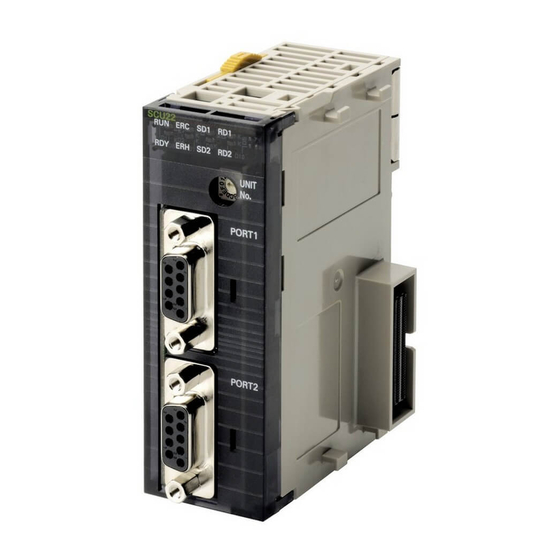
Port 1: SDA- RS-232C Port 1: SDA+ RS-422A/485 terminal-block connector PORT2 PORT2 Port 2: Port 2: RS-232C RS-232C CJ1W-SCU32 SCU32 RD1 TER1 Indicators RD2 TER2 Terminating TERM UNIT resistance Bottom view WIRE switch (for port 1) Unit number PORT1 (RS422... -
Page 77: Troubleshooting And Maintenance
*2 System settings use the device variables for CJ-series Unit determined by the unit number setting. For details, refer to 2-3-2 Device Variable for CJ-series Unit for System Settings. *3 Only the CJ1W-SCU32/SCU42 are equipped with a TER1 indicator. *4 Only the CJ1W-SCU32 is equipped with a TER2 indicator. - Page 78 2 Initial Settings and Allocations of Device Variable for CJ-series Unit RS-232C Ports Protocol Protocol macro Communications Full-duplex or half-duplex method Synchronization Start-stop synchronization (asynchronous) 1200/2400/4800/9600/19200/38400/57600/ Baud rate 115200/230400 bps Connections 1:1 (1:N is possible with Link Adapters) Transmission 15 m max. (*) distance Interface Complies with EIA RS-232C...
- Page 79 NT-AL001 Link Adapter. Otherwise, the external device and the Serial Com- munications Unit may be damaged. Use the OMRON Cables specified in this manual or make your own cables. Do not use commer- cially available RS-232C cables sold for personal computers. Otherwise, the external device and the Serial Communications Unit may be damaged.
- Page 80 2 Initial Settings and Allocations of Device Variable for CJ-series Unit Connector Pin Layout Abbrevia- Pin No. Signal name tion 1 (*1) Receive data - Input 2 (*1) Receive data + Input 3 (*1) Send data - Output 4 (*1) Send data + Output 5 (*2)
- Page 81 2 Initial Settings and Allocations of Device Variable for CJ-series Unit Dimensions (Unit: mm) CJ1W-SCU22 SCU22 UNIT PORT1 PORT2 CJ1W-SCU32 81.9 SCU32 RD1 TER1 RD2 TER2 TERM UNIT WIRE PORT1 (RS422 /485) RDA- RDA+ SDA- SDA+ PORT2 (RS422 /485) RDA-...
-
Page 82: Data Exchange With The Cpu Unit
2 Initial Settings and Allocations of Device Variable for CJ-series Unit Data Exchange with the CPU Unit Data exchange between this Unit and the CPU Units uses the I/O port allocated to the Serial Communi- cations Unit or memory used for CJ-series Unit, if necessary. For details on I/O ports, refer to 2-3 Device Variable for CJ-series Unit. - Page 83 2 Initial Settings and Allocations of Device Variable for CJ-series Unit NJ-series CPU Unit Serial Communications Unit User program I/O port Operation Data For input Status (for port 1) Device variable for AT specification Status and CJ-series Unit software Status (for port 2) switch data I/O refresh For output...
- Page 84 2 Initial Settings and Allocations of Device Variable for CJ-series Unit Device variable for CJ-series Unit Device variables for CJ-series Units are variables for which AT is specified for the I/O port explained below. The user program uses device variables for CJ-series Unit to access the Configuration Unit such as Serial Communications Unit.
- Page 85 2 Initial Settings and Allocations of Device Variable for CJ-series Unit User-defined variable The user program uses user-defined variables to access the storage area for the send/receive data, or holding resisters and other allocation areas in the Modbus-RTU Slave Mode, with a communications instruction.
-
Page 86: How To Specify And Create Variables
2 Initial Settings and Allocations of Device Variable for CJ-series Unit How to Access from User Program The CPU Unit and the Serial Communications Unit exchange data via the memory within the CPU Unit used for the CJ-series Unit. For details of the memory used for CJ-series Unit, refer to NJ-series CPU Unit Software User's Manual (W501). - Page 87 2 Initial Settings and Allocations of Device Variable for CJ-series Unit How to Create User-defined Variables User-defined variables are required in the following situations. • To specify the send/receive data of Serial Port I/O instructions in No-protocol Mode • To specify the send/receive data with a Protocol Macro instruction in Protocol Macro Mode •...
-
Page 88: Device Variable For Cj-Series Unit
2 Initial Settings and Allocations of Device Variable for CJ-series Unit Device Variable for CJ-series Unit The function of each device variable for CJ-series Unit is explained in this section. The following explanations use variables names automatically created on the I/O Map View of Sysmac Studio. - Page 89 2 Initial Settings and Allocations of Device Variable for CJ-series Unit System Setting Procedure You can use the following methods to set the Unit settings. Use CX-Protocol or Special Unit Setup Editing screen of Sysmac Studio. Use a user program. If it is necessary to change the System Settings while the user program is executed, use the user pro- gram to change the System Settings.
- Page 90 2 Initial Settings and Allocations of Device Variable for CJ-series Unit List of Device Variable for CJ-series Unit for System Settings *_ in a device variable name for CJ-series Unit corresponds to the device name of this Unit. By default, a device name is assigned from "J01" in the order of registration in the Unit Configuration. This identifies the individual unit.
- Page 91 2 Initial Settings and Allocations of Device Variable for CJ-series Unit Device variable for CJ-series Unit Type Name Function Port 1 Port 2 *_P1_ParityYNCfg *_P2_ParityYNCfg BOOL Parity FALSE: Yes TRUE: No Default: FALSE *_P1_ParityBitCfg *_P2_ParityBitCfg BOOL Parity FALSE: Even Even/Odd TRUE: Odd Default: FALSE *_P1_BaudrateCfg...
- Page 92 2 Initial Settings and Allocations of Device Variable for CJ-series Unit Protocol Macro Mode Device variable for CJ-series Unit Type Name Function Port 1 Port 2 *_P1_SendDelayCfg *_P2_SendDelayCfg WORD Send Delay Bit 15: Send delay time Settings Bits 00 to 14: Send delay time (user-specified) *_P1_SendDelaySetCfg *_P2_SendDelaySetCfg...
- Page 93 2 Initial Settings and Allocations of Device Variable for CJ-series Unit Device variable for CJ-series Unit Type Name Function Port 1 Port 2 *_P1_PmrRBufClrCfg *_P2_PmrRBufClrCfg BOOL Clearing/Hold- FALSE: Clear (default) ing the Con- TRUE: Hold tents of the Reception Buffer in Full- duplex Mode *_P1_PmrLkChAccessCfg *_P2_PmrLkChAccessCfg BOOL...
- Page 94 2 Initial Settings and Allocations of Device Variable for CJ-series Unit Serial Gateway Mode Device variable for CJ-series Unit Type Name Function Port 1 Port 2 *_P1_SendDelayCfg *_P2_SendDelayCfg WORD Send Delay Bits serve the functions Settings described below. Bit 15: Send delay time Bits 00 to 14: Send delay Time (user-specified) *_P1_SendDelaySetCfg...
- Page 95 2 Initial Settings and Allocations of Device Variable for CJ-series Unit No-protocol Mode Device variable for CJ-series Unit Type Name Function Port 1 Port 2 *_P1_SendDelayCfg *_P2_SendDelayCfg WORD Send Delay Bits serve the functions Settings described below. Bit 15: Send delay timer Bits 00 to 14: Send delay Time (user-specified) *_P1_SendDelaySetCf...
- Page 96 2 Initial Settings and Allocations of Device Variable for CJ-series Unit Modbus-RTU Slave Mode Device variable for CJ-series Unit Type Name Function Port 1 Port 2 *_P1_MbsSlavAdrCfg *_P2_MbsSlavAdrCfg USINT Modbus-RTU Range: 1 to 247 Slave Address Default: 0 *_P1_MbsCoilsAreaCfg *_P2_MbsCoilsAreaCfg BYTE Coils Alloca- 16#00: CIO (default)
-
Page 97: Device Variable For Cj-Series Unit For Software Switches
2 Initial Settings and Allocations of Device Variable for CJ-series Unit 2-3-3 Device Variable for CJ-series Unit for Software Switches (Output from the CPU Unit to Serial Communications Unit) The software switches are used for loopback tests, aborts in Protocol Macro Mode, releasing wait sta- tus, etc. -
Page 98: Device Variable For Cj-Series Unit For Status
2 Initial Settings and Allocations of Device Variable for CJ-series Unit 2-3-4 Device Variable for CJ-series Unit for Status These variables are used for data input from the Serial Communications Unit to the CPU Unit. With statuses, you can read the setting status, communications status, transmission control signal sta- tus, and transmission error status of each Serial Communications Unit port common to each Communi- cations Mode, and you can read the protocol status unique to each Communications Mode. - Page 99 2 Initial Settings and Allocations of Device Variable for CJ-series Unit Device variable for CJ-series Unit Type Name Function Port 1 Port 2 *_P1_StartBitSta *_P2_StartBitSta BOOL Start Bits FALSE: 1 bit (Always 1 bit) TRUE: 1 bit (1 bit for both FALSE and TRUE) *_P1_DatBitSta *_P2_DatBitSta...
- Page 100 2 Initial Settings and Allocations of Device Variable for CJ-series Unit Device variable for CJ-series Unit Type Name Function Port 1 Port 2 *_P1_LclBusySta *_P2_LclBusySta BOOL Local Unit Busy TRUE: Local Unit busy (Flow control) FALSE: Local Unit ready to receive *_P1_SigERSta *_P2_SigERSta BOOL...
- Page 101 2 Initial Settings and Allocations of Device Variable for CJ-series Unit Device variable for CJ-series Unit Type Name Function Port 1 Port 2 There is no specific There is no specific Number of Range: 0 to 9 device variable for CJ- device variable for CJ- string Retries (*3)
- Page 102 2 Initial Settings and Allocations of Device Variable for CJ-series Unit List of Device Variables for CJ-series Unit for Statuses Specific to Each Communications Mode (Protocol Statuses) Protocol Macro Mode Device variable for CJ-series Unit Type Name Function Port 1 Port 2 *_P1_PmrSta *_P2_PmrSta...
- Page 103 2 Initial Settings and Allocations of Device Variable for CJ-series Unit Device variable for CJ-series Unit Type Name Function Port 1 Port 2 *_P1_PmrAbtSta *_P2_PmrAbtSta BOOL Abort Flag This flag is changed to TRUE when processing is ended by using the abort switch from the user pro- gram.
- Page 104 2 Initial Settings and Allocations of Device Variable for CJ-series Unit Device variable for CJ-series Unit Type Name Function Port 1 Port 2 *_P1_PmrSgwProhSta *_P2_PmrSgwProhSta BOOL Serial Gateway This flag is changed to Prohibited Flag TRUE when the Serial (Protocol Mac- Gateway function (mode) ros) is prohibited due to the...
- Page 105 2 Initial Settings and Allocations of Device Variable for CJ-series Unit Loopback Tests Device variable for CJ-series Unit Type Name Function Port 1 Port 2 *_P1_LbtSta *_P2_LbtSta WORD Loopback Test Bit 15: Error Status Bit 08: DTR check error Bit 07: CTS check error Bit 05: Timeout error Bit 04: Parity error Bit 03: Overrun error...
- Page 106 2 Initial Settings and Allocations of Device Variable for CJ-series Unit No-protocol Mode Device variable for CJ-series Unit Type Name Function Port 1 Port 2 *_P1_NopSta *_P2_NopSta WORD No-protocol Bit 07: Reception Overflow Mode Status Flag Bit 06: Reception Com- pleted Flag Bit 05: SerialSend Execut- ing Flag...
- Page 107 2 Initial Settings and Allocations of Device Variable for CJ-series Unit Modbus-RTU Slave Mode Device variable for CJ-series Unit Type Name Function Port 1 Port 2 *_P1_MbsCmdRxCntSta *_P2_MbsCmdRxCntSta UINT Number of Nor- The number of normal mally Received Modbus-RTU commands Commands received from the commu- nications port is stored.
-
Page 108: System-Defined Variable
2 Initial Settings and Allocations of Device Variable for CJ-series Unit System-defined Variable Serial Communications Unit Port 1/2 Settings Changing Flag and Restart Bits are allocated to the fol- lowing system-defined variables. Port 1 and Port 2 Settings Changing Flag You can use an Out instruction or another instruction from the program to change these flags to TRUE to change communications settings and restart the Serial Communications Unit ports. - Page 109 2 Initial Settings and Allocations of Device Variable for CJ-series Unit Variables Related to the SerialSend, SerialRcv, and SerialRcvNoClear Instructions in No-protocol Mode System-defined variable Description _Port_isAvailable Network Communications Instruction Enabled Flag TRUE when execution of SerialSend, SerialRcv, SerialRcvNoClear, and other net- work communications instructions (such as SendCmd and ExecPMCR) is enabled.
- Page 110 2 Initial Settings and Allocations of Device Variable for CJ-series Unit 2-36 CJ-series Serial Communications Units Operation Manual for NJ-series CPU Unit(W494)
- Page 111 Wiring RS-422A/485 Terminal-block Connectors on the CJ1W-SCU32/42 ....... 3-25 3-3-7 Connecting to Unit .
-
Page 112: Installing Serial Communications Units
3 Installation and Wiring Installing Serial Communications Units 3-1-1 System Configuration Precautions • Set a unique Unit number for each CPU Bus Unit to be installed in the CPU Rack or Expansion Rack. Set the unit number switch at the top of the front panel to between 0 and F. Turn OFF the Controller before setting the unit number. -
Page 113: Unit Handling Precautions
3 Installation and Wiring Precautions for Safe Use If the sliders are not locked properly, the Serial Communications Units may not function correctly. To remove the Unit, move the sliders to the release position and then pull the Units gently apart. 3-1-3 Unit Handling Precautions •... -
Page 114: Wiring
The following port types are provided on the Serial Communications Units. Model Port 1 Port 2 CJ1W-SCU22 RS-232C RS-232C CJ1W-SCU32 RS-422A/485 RS-422A/485 CJ1W-SCU42 RS-422A/485 RS-232C The following sections describe the connection methods used for each serial communications mode and Serial Communications Unit port. -
Page 115: Connector Pin Layout
Data terminal ready Output Signal ground Shell Shield Refer to 2-1 Component Names and Functions. RS-422A/485 Port: Ports 1 and 2 on CJ1W-SCU32, or Port 1 on CJ1W-SCU42 Connector Pin Layout Pin No. Symbol Signal name Receive data − Input... -
Page 116: Mounting Height And Connector Cover Dimensions
Check the polarity of the external device before you make connections. Additional Information The RS-422A/485 port on the CJ1W-SCU32/42 has a failsafe function built into the receiver to prevent reading incorrect signals when the RDA and RDB pins are open or shorted. -
Page 117: Reducing Electrical Noise For External Wiring
3 Installation and Wiring 3-2-6 Reducing Electrical Noise for External Wiring Observe the following precautions for external wiring. • When multi-conductor signal cable is used, avoid use of I/O wires and other control wires in the same cable. • If wiring racks are running in parallel, allow at least 300 mm between the racks. Low-current cables Communications cables... -
Page 118: Nt-Al001 Link Adapter Settings
3 Installation and Wiring Precautions for Correct Use Precautions for Correct Use • Use the same transmission circuit (2-wire or 4-wire) for all nodes. • Do not use 4-wire connections when the 2/4-wire switch on the Unit is set to 2-wire. •... -
Page 119: Connections For Protocol Macro, Serial Gateway, No-Protocol Mode, And Modbus-Rtu Slave Mode
3 Installation and Wiring 3-2-9 Connections for Protocol Macro, Serial Gateway, No-protocol Mode, and Modbus-RTU Slave Mode This section describes the connections for Protocol Macro, Serial Gateway, and No-protocol Mode. Up to 32 Boards or Units can be used for 1:N connections. Port Config- Schematic diagram... - Page 120 3 Installation and Wiring Port Config- Schematic diagram uration RS-422A/485 interface 422A/485 RS-422A/485 RS-232C interface NT-AL001 RS-232C RS-422A/485 Resistance ON 5-V power RS-422A/485 interface 422A/485 RS-422A/485 Resistance Resistance ON RS-422A/485 interface B500-AL001-E RS-422A/485 Resistance Resistance ON RS-232C interface NT-AL001 RS-232C Resistance RS-232C RS-422A/485...
- Page 121 3 Installation and Wiring Connection diagrams are provided in the following subsections. OMRON recommends the use of shielded, twisted-pair cables for actual wiring to enhance noise resistance. For details on wiring meth- ods, refer to 3-3 RS-232C and RS-422A/485 Wiring.
- Page 122 3 Installation and Wiring Connections to Personal Computer with RS-CS Flow Control • IBM PC/AT or Compatible Computers • DOS/V or Compatible Computers Serial Communications Serial Communications Unit Unit Computer RS-232C port Computer RS-232C port Using NT-AL001 Link Adapters Serial Communications Unit NT-AL001 Link Adapter NT-AL001 Link Adapter...
- Page 123 3 Installation and Wiring Connections to a Modem Serial Communica- tions Unit RS-232C port Modem CJ-series Serial Communications Units Operation Manual for NJ-series CPU Unit(W494) 3-13...
- Page 124 3 Installation and Wiring 1:N Connections Using RS-232C Ports Device that supports RS-422A/485 communications (4-wire) Serial Communications Unit NT-AL001 RS-232C Signal RS-422A Signal Shield Signal Signal RS-422A Shield /485 interface RS-232C Device that supports interface RS-422A/485 communications (4-wire) Signal RS-422A D-sub, 9-pin D-sub, 9-pin Terminal block...
- Page 125 3 Installation and Wiring 1:1 Connections Using RS-422A/485 Ports Device that supports Device that supports RS-422A/485 RS-422A/485 communications communications Serial Communications Unit (4-wire) Serial Communications Unit (2-wire) Signal Signal Pin Signal Pin Signal Shield Shield RS-422A /485 in- A(−) RS-422A terface RS-422A /485 in-...
- Page 126 3 Installation and Wiring 1:N Connections Using RS-422A/485 Ports Device that supports RS-422A/485 communications Serial Communications Unit (2-wire) Signal Signal RS-422A/ 485 Inter- A(−) face RS-422A/ B(+) 485 Inter- face Terminal block connector Device that supports RS-422A/485 communications (2-wire) Signal RS-422A/ 485 Inter- A(−)
- Page 127 3 Installation and Wiring Serial Communications Unit NT-AL001 Signal Pin RS-422A Shield Pin Signal Signal Pin Signal RS-232C RS-422A /485 in- terface RS-232C Interface 4-wire Terminal Terminating block resistance: ON connector Shield RS-422 RS-232 5-V power Terminal block D-sub, 9-pin connector DIP switch pin (male)
-
Page 128: 3-2-10 Connections In Loopback Test
3 Installation and Wiring 3-2-10 Connections in Loopback Test Connect the communications ports as shown below. RS-232C port RS-422A/485 port Signal Signal 3-18 CJ-series Serial Communications Units Operation Manual for NJ-series CPU Unit(W494) -
Page 129: Rs-232C And Rs-422A/485 Wiring
3 Installation and Wiring RS-232C and RS-422A/485 Wiring 3-3-1 Recommended RS-232C Wiring Examples It is recommended that RS-232C cables be connected as described below especially when the Serial Communications Unit is used in an environment where it is likely to be subject to electrical noise. Always use shielded twisted-pair cables as communications cables. -
Page 130: Recommended Rs-422A/485 Wiring Examples
3 Installation and Wiring Power Supply Unit Serial Communications Unit SCU22 UNIT PORT1 PORT2 Ground to 100 Ω Hood and GR are internally connected. or less. Ground the GR terminal to ground the Shell (FG). 3-3-2 Recommended RS-422A/485 Wiring Examples Recommended RS-422A/485 Cable We recommend the following wiring method to ensure transmission quality. - Page 131 3 Installation and Wiring Connection examples are shown with the following diagrams. 2-wire Connections Serial Communications Unit Signal Remote device Signal A(−) B(+) Shield 4-wire Connections Serial Communications Unit Remote device Signal Signal Shield Serial Communications Unit Remote device RS-422 Signal Signal Remote device...
-
Page 132: Wiring Rs-232C Connectors On The Cj1W-Scu22/42
3 Installation and Wiring 3-3-3 Wiring RS-232C Connectors on the CJ1W-SCU22/42 Use the following steps to wire connectors. Cable Preparation See the following diagrams for the length of the cable portion to be cut in each step. Shield Connected to Shell (FG) Cut the cable to the required length. -
Page 133: Soldering
3 Installation and Wiring Remove the specified length of the sheath from the cable by using a knife. Be careful not to scratch the braided shield. 25 mm (RS-422A) 40 mm (RS-232C) Trim off all the braided shield by using scissors. Remove the insulation from each conductor by using a stripper so that the exposed conductor length is 5 mm. -
Page 134: Assembling Connector Hood
3 Installation and Wiring Return the heat-shrinking tube to the soldered portion, then heat the tube to shrink it in place. Heat-shrinking tube 3-3-5 Assembling Connector Hood Assemble the connector hood as shown below. Adhesive tape End connected to FG End not connected to FG Aluminum foil tape Grounding plate... -
Page 135: Wiring Rs-422A/485 Terminal-Block Connectors On The Cj1W-Scu32/42
3 Installation and Wiring 3-3-6 Wiring RS-422A/485 Terminal-block Connectors on the CJ1W- SCU32/42 Applicable Connectors Use one of the following connectors. Manufacturer and model Comments Phoenix Contact Screwless terminals (provided with Unit) FMC1.5/5-STF-3.5AU Phoenix Contact Screw terminals MC1.5/5-STF-3.5AU Purchase separately from the manufacturer. Note To connect two wires to one terminal, use the terminal-block connector with screw terminals and connect the two wires to one terminal with or without ferrules designed for two wires. -
Page 136: Connecting To Unit
Unit. Then tighten the screws to secure the connector to the Unit. Recommended tightening torque: 0.2 to 0.3 N⋅m 3-3-7 Connecting to Unit CJ1W-SCU22 Tighten the screws firmly with your fingers. CJ1W-SCU32/42 CJ1W-SCU32 CJ1W-SCU42 Serial Communications Unit Serial Communications Unit Cable connector 3-26... -
Page 137: Using Protocol Macros
Using Protocol Macros This section describes the procedure and other information required to use protocol macros. 4-1 Overview of the Protocol Macro Function ......4-2 4-1-1 Protocol Macros . -
Page 138: Overview Of The Protocol Macro Function
The following three methods are available to use the protocol macros. Using the Standard System Protocols It is possible to connect OMRON devices and the NJ-series CPU Unit by specifying the sequence number of the standard system protocols in the Protocol Macro instruction (ExecPMCR). The sys- tem protocols are prepared in the Serial Communications Unit and CX-Protocol. - Page 139 4 Using Protocol Macros Modifying Standard System Protocols When you connect OMRON devices, if there is no standard system protocol or you wish to modify part of the protocol, use the CX-Protocol to modify the standard system protocol, transfer this as a separate communications sequence to the Serial Communications Unit, and execute the ExecP- MCR instruction.
-
Page 140: Protocol Structure
In this manual, the protocol structure is explained in simple terms, and examples are given of the use of the ExecPMCR instruction during control of OMRON devices by using standard system proto- cols. For details on the protocols, the modification method for standard system protocols, and the creation method for new sequences, refer to the CX-Protocol Ver.1.9 OPERATION MANUAL (Cat. - Page 141 4 Using Protocol Macros Depending on the response received, this function can either choose to resend the same send mes- sage (retry processing), or to perform the next process (for example, read the process value for a Tem- perature Controller with a different address). One protocol One-step structure Sequence No.
- Page 142 4 Using Protocol Macros Step Parameters Parameter Meaning Command One of the following: Send, Recv, Send&Recv, Wait, Flush, Open, or Close Messages Send message The message sent for Send. Receive message The expected message for Recv. Send message and Both the message sent and the expected receive message receive message for Send&Recv.
- Page 143 4 Using Protocol Macros Standard System Protocol Example Example: Variable Area Read (Sequence No. 610) Sequence for CompoWay/F Master Protocol Level Item Setting Sequence Link words Transmission control Modem control parameters Response notification Scan method Receive Wait Monitoring Time Tr Receive Finished Monitor- ing Time Tfr Send Finished Monitoring...
- Page 144 4 Using Protocol Macros A) Structure of Variable Area Read (MRC/SRC: 0101)* send message Variable type Read start address Bit number Number of elements B) Structure of Variable Area Read (MRC/SRC: 0101)* receive message Response code Read data (for number of elements) ×...
- Page 145 Data Handling Communications Problems for Standard System Protocols The NJ-series PLCs provide standard system protocols to enable communications with OMRON com- ponents without creating communications sequences. You can execute the sequences in the standard system protocols merely executing ExecPMCR instruction after specifying the sequence number and command data.
-
Page 146: Data Exchange Method For Link Words
4 Using Protocol Macros Level Item Possible changes in settings Sequence Transmission control Setting change unnecessary. parameters parameters Link words Response notifica- tion method Receive Wait Moni- The monitoring times are set to 3 seconds for most sequences. The set- toring Time Tr tings are different for send-only and receive-only sequences, as well as for sequences that require time for responses. - Page 147 4 Using Protocol Macros CPU Unit Unit (1) to (4) are performed in User program order for the processing within Communications this dotted line. sequence ExecPMCR Step 0 Send message according Step 1 (send) to Send command (4) Send R (O1, 2) Read and compile message Link word 1 User-defined variables...
- Page 148 4 Using Protocol Macros Additional Information If continuous I/O refreshing is specified for the data exchange method for link words, I/O refresh- ing is executed during the execution of protocol macros between the CPU Unit and the Unit with- out synchronizing with the execution of Send/Receive commands. Therefore it is necessary to pay attention to the data exchange method at the start and end of the protocol macros.
-
Page 149: Device Variables For Cj-Series Unit And System-Defined Variables (Protocol Macro Mode)
4 Using Protocol Macros Device Variables for CJ-series Unit and System-defined Variables (Protocol Macro Mode) This section describes the device variables for CJ-series Unit and system-defined variables used in the Protocol Macro Mode. 4-2-1 Device Variable for CJ-series Unit for System Settings Use the device variables for CJ-series Unit shown below to perform System Settings when you use the Serial Communications Unit in Protocol Macro Mode. - Page 150 4 Using Protocol Macros Device variable for CJ-series Unit Type Name Function Port 1 Port 2 *_P1_ParityYNCfg *_P2_ParityYNCfg BOOL Parity FALSE: Yes TRUE: No Default: FALSE *_P1_ParityBitCfg *_P2_ParityBitCfg BOOL Parity FALSE: Even Even/Odd TRUE: Odd Default: FALSE *_P1_BaudrateCfg *_P2_BaudrateCfg USINT Baud Rate 0: 9600, 3: 1200, 4: 2400 (unit: bps)
-
Page 151: Area Descriptions
4 Using Protocol Macros Device variable for CJ-series Unit Type Name Function Port 1 Port 2 *_P1_PmrMaxDatSzCfg *_P2_PmrMaxDatSzCfg UINT Maximum 200 to 1,000 bytes Number of Set 1,000 bytes when Bytes in Proto- standard system protocol col Macro is used. Send/Receive Data * When the default settings are used, the Baud Rate, Start Bits, Data Length, Stop Bits, Parity Yes/No, and Parity... - Page 152 4 Using Protocol Macros If a timeout occurs, a command end code (0204 hex (Remote node busy)) is returned to the com- mand source. The send processing is not executed and the received command is discarded. Protocol Macro Transmission Method Set half-duplex (FALSE) or full-duplex (TRUE) depending on the transmission mode for the external device.
- Page 153 4 Using Protocol Macros With full-duplex mode, the reception buffer is cleared immediately before the sequence is executed. While Recv and Send commands are executed, data is input into the reception buffer and is used as the protocol macro data. Transmission Time reception Data reception...
- Page 154 4 Using Protocol Macros Clearing/Holding the Contents of the Reception Buffer in Full-duplex Mode Set to either clear or hold the contents of the reception buffer when the protocol macro starts. FALSE: Clear When set to clear, the contents of the reception buffer will be cleared when the protocol macro is executed.
- Page 155 4 Using Protocol Macros RS/CS Flow Control Half-duplex Communications With NJ-series half-duplex protocol macro communications, flow control can be released by turning ON the RTS (RS) signal (CTS (CS) signal at the Remote Unit) while the Recv command is executed. ExecPMCR ExecPMCR instruction instruction...
- Page 156 4 Using Protocol Macros Full-duplex Mode There is a 2.5 KB reception buffer for each serial port in full-duplex mode of NJ-series Protocol Macro Mode. When flow control is used, initiate flow control after receiving about 2 KB, and then release control after processing all but 0.5 KB of receive data.
-
Page 157: System-Defined Variable
4 Using Protocol Macros 4-2-3 System-defined Variable Port 1 and Port 2 Port Settings Changing Flags You can use an Out instruction or other instruction in the program to turn these bits from FALSE to TRUE to change communications settings and restart the Serial Communications Unit ports. After you change the settings and restart the communications port, the flag will automatically change to FALSE. -
Page 158: Devices Variable For Cj-Series Unit For Software Switches
4 Using Protocol Macros 4-2-4 Devices Variable for CJ-series Unit for Software Switches The device variables can be used to execute various commands for the Serial Communications Unit. List of Areas Device variable for CJ-series Unit Type Name Function Port 1 Port 2 *_P1_SoftSw *_P2_SoftSw... - Page 159 4 Using Protocol Macros Software Switch Descriptions The Software Switches function as described in the following table. Device vari- Timing Name able for CJ- Meaning Initialize Reset series Unit Serial Gate- *_P1_SgwDsbl The Serial Gateway (Mode) is prohib- Controller Manipulated Manipulated way Prohibit ited during protocol macro processing...
-
Page 160: Device Variables For Cj-Series Unit For Status
4 Using Protocol Macros 4-2-5 Device Variables for CJ-series Unit for Status These variable are used for data input from the Serial Communications Unit to the CPU Unit. You can reference the Serial Communications Unit port settings status, communications status, the transmission control signal status, and the transmission error status. - Page 161 4 Using Protocol Macros Device variable for CJ-series Unit Type Name Function Port 1 Port 2 *_P1_ParityBitSta *_P2_ParityBitSta BOOL Parity FALSE: Even (Even/Odd) TRUE: Odd *_P1_HwSetSta *_P2_HwSetSta WORD Hardware Bit 15: RS-422/485 setting Settings status Bit 14: RS-232C setting Bit 13: Terminating resis- tance setting status Bit 01: System Setup error Bit 00: Port operating sta-...
- Page 162 4 Using Protocol Macros Device variable for CJ-series Unit Type Name Function Port 1 Port 2 *_P1_TransErrSta *_P2_TransErrSta WORD Transmission Bit 15: Transmission error Error Status (*4) Bit 14: Tfs (send finished monitoring time) exceeded Bit 13: Tfr (receive fin- ished monitoring time) exceeded Bit 12: Tr (receive wait...
- Page 163 4 Using Protocol Macros Device variable for CJ-series Unit Type Name Function Port 1 Port 2 *_P1_OverRunErr *_P2_OverRunErr BOOL Overrun Error TRUE: Overrun error FALSE: Normal *_P1_FramingErr *_P2_FramingErr BOOL Framing Error TRUE: Framing error FALSE: Normal *_P1_ParityErr *_P2_ParityErr BOOL Parity Error TRUE: Parity error FALSE: Normal *1 The current settings for the port are read.
- Page 164 4 Using Protocol Macros Status Area Descriptions Device vari- Timing Name able for CJ- Meaning Initialize Reset series Unit Error Log *_Com_UnitLog If a write to EEPROM fails for the error log, Controller At error When power EEPROM MemErr it is assumed the EEPROM is beyond its reset (*) is cycled Error...
- Page 165 4 Using Protocol Macros Device vari- Timing Name able for CJ- Meaning Initialize Reset series Unit Local Unit *_P1_LclBusyS This variable indicates the receive status Controller When status After busy Busy of the Local Unit (Unit) during Recv when reset (*) is read status is *_P2_LclBusyS...
- Page 166 4 Using Protocol Macros Device vari- Timing Name able for CJ- Meaning Initialize Reset series Unit Hardware *_P1_HwSetSt The following are read in port setting sta- Controller When status When the Settings tus: reset (*) is read error is *_P2_HwSetSt cleared after 1.
- Page 167 4 Using Protocol Macros Additional Information Overrun Errors, Framing Errors, Parity Errors and Error Flags If an overrun error, framing error, or parity error is detected when the protocol macros is used, the receive data will be stored in the buffer with the error status included. The corresponding error flags will change to TRUE the following conditions are met.
-
Page 168: Protocol Status
4 Using Protocol Macros 4-2-6 Protocol Status The information shown in the following table is input from the Unit to the Protocol Status Words in the CPU Unit. Device variable for CJ-series Unit Type Name Function Port 1 Port 2 *_P1_PmrSta *_P2_PmrSta WORD... - Page 169 4 Using Protocol Macros Device variable for CJ-series Unit Type Name Function Port 1 Port 2 *_P1_PmrAbtSta *_P2_PmrAbtSta BOOL Abort Flag This flag is changed to TRUE when processing is ended by using the Abort Switch from the user pro- gram.
- Page 170 4 Using Protocol Macros Device variable for CJ-series Unit Type Name Function Port 1 Port 2 *_P1_PmrSgwProhSta *_P2_PmrSgwProhSta BOOL Serial Gateway This flag is set to TRUE Prohibited Flag when the Serial Gateway (Protocol Mac- function (Mode) is prohib- ros) ited due to the status of the Serial Gateway Pro- hibit Switch in the user...
- Page 171 4 Using Protocol Macros Device variable for CJ-series Unit Type Name Function Port 1 Port 2 *_P1_PmrRepCntSta *_P2_PmrRepCntSta WORD Repeat Bits 08 to 15: Repeat Counter Counter Setting Value Bits 00 to 07: Repeat Counter Present Value *_P1_PmrSetRepCntS *_P2_PmrSetRepCntS USINT Repeat The number of times a Counter Set-...
- Page 172 4 Using Protocol Macros Protocol Status Area Descriptions Timing Device variable for Name Meaning CJ-series Unit Initialize Reset Protocol *_P1_PmrExecSta This flag is changed to TRUE when a ExecP- Controller When When Macro Exe- MCR instruction (sequence) is executed. The reset (*) instruc- instruc-...
- Page 173 4 Using Protocol Macros Timing Device variable for Name Meaning CJ-series Unit Initialize Reset Sequence *_P1_PmrSeqWaitSt This flag is changed to TRUE when a Controller When When Wait Flag sequence is waiting due to the Wait command. reset (*) Wait com- Wait mand is Release...
- Page 174 4 Using Protocol Macros Timing Device variable for Name Meaning CJ-series Unit Initialize Reset Executed *_P1_PmrRcvCaseN Reception matrix case numbers 0 to 15 (0 to F Controller When When Reception oCodeSta hex) for which reception is complete are reset (*) matrix is sequence Case No.
- Page 175 4 Using Protocol Macros Precautions for Correct Use Precautions for Correct Use Data read/write area exceeded error will occur in the Protocol Status if an EM bank that does not exist is specified in the Protocol Macro Mode. CJ-series Serial Communications Units Operation Manual for NJ-series CPU Unit(W494) 4-39...
-
Page 176: Using Protocol Macros
4 Using Protocol Macros Using Protocol Macros 4-3-1 Executing Communications Sequences Use the ExecPMCR instructions to execute communications sequences. The ExecPMCR instruction is supported by the NJ-series CPU Unit. For details on the ExecPMCR instruction, refer to the NJ-series Instructions Reference Manual (Cat. No. W502). When a ExecPMCR instruction is executed, the communications sequence specified in SeqNo is exe- cuted from the serial port (physical port) of the device with the unit number specified in Port. - Page 177 4 Using Protocol Macros SrcDat (Send Data Array Starting Element) Specifies the word array starting element of the Send Area. Although the size is set for word array SendData[0] (user-defined variable), set a value that includes the storage area of that size. Size SendData[0] SendData[1]...
-
Page 178: User Program Example
The following diagram shows an example in which sequence number 610 (Variable Area Read) of the CompoWay/F Master Protocol is executed by using the protocol for an OMRON component connected to port 1 (RS-422A/485) of the CJ-series Serial Communications Unit. - Page 179 4 Using Protocol Macros Send data Word data array Description of this Variable Item Value example SendData[0] Number of send data words Data of 5 words of Send- WORD#16#0005 Data[0] to SendData[4] are sent. SendData[1] Node No. Node No. 3. WORD#16#0003 SendData[2] Variable type + higher 1...
- Page 180 4 Using Protocol Macros Example of User Program Creation In the following example, sequence number 610 (Variable Area Read) of a CompoWay/F Master (Vari- able Area Read) is executed by the ExecPMCR instruction and the present value that was read upon successful completion of the sequence is transferred to another user-defined variable (defined as Tmp- Data here).
- Page 181 4 Using Protocol Macros System-defined variable Data Factory Name Comments Details type setting _Port_isAvailable BOOL Network Communica- This flag becomes TRUE when tions Instruction there are internal logic ports Enabled Flag available, FALSE when there is no internal logic port available. User-defined variables (To be defined before or when creating a program) Allocated Name...
- Page 182 4 Using Protocol Macros Device variables for CJ-series Unit (To be created on the I/O Map View window after the unit configuration is created) Data Factory Allocated Name Comments Details type setting address (AT) SCU_P1_PmrExecSt BOOL IOBus://rack#0/slo Port 1: This flag becomes TRUE t#0/P1_PmrSta/P Protocol when a ExecPMCR...
- Page 183 4 Using Protocol Macros Program Example Determining the ExecPMCR instruction execution completion ExecPMCR_instance.Done OperatingEnd ExecPMCR_instance.Error Trigger reception RS_instance Trigger _Port_isAvailable SCU_P1_PmrExecSta ExecPMCR_instance.Busy Operating OperatingEnd Reset1 Communications parameters settings Inline ST Operating 1 InPort.UnitNo :=_eUnitNo#_CBU_No02; //Serial Communications Unit, Unit number 2 2 InPort.PhysicPortNo:=USINT#1;...
- Page 184 4 Using Protocol Macros System-defined variable Data Factory Name Comments Details type setting _Port_isAvailable BOOL Network Communica- This flag becomes TRUE when tions Instruction there are internal logic ports Enabled Flag available, FALSE when there is no internal logic port available. User-defined variables (To be defined before or when creating a program) Allocated Name...
- Page 185 4 Using Protocol Macros Device variables for CJ-series Unit (To be created on the I/O Map View window after the unit configuration is created) Data Factory Allocated Name Comments Details type setting address (AT) SCU_P1_PmrExecSt BOOL IOBus://rack#0/slo Port 1: This flag becomes TRUE t#0/P1_PmrSta/P Protocol when a ExecPMCR...
- Page 186 4 Using Protocol Macros Program Example //Trigger reception IF ( State = INT#0 ) THEN IF (( Trigger = TRUE ) AND ( _Port_isAvailable = TRUE ) AND ( SCU_P1_PmrExecSta <> TRUE ) AND ( ExecPMCR_instance.Busy <> TRUE )) THEN State := INT#1;...
- Page 187 4 Using Protocol Macros IF ( ExecPMCR_instance.Error = TRUE ) THEN State := INT#5; END_IF; END_IF; //Checking for ExecPMCR instruction execution completion IF ( State = INT#3 ) THEN IF( SCU_P1_PmrSeqEndSta = TRUE ) THEN State := INT#4; END_IF; IF( SCU_P1_PmrSeqAbtSta = TRUE ) THEN State := INT#5;...
- Page 188 4 Using Protocol Macros Additional Information Usage of Receive Data Area before execution of ExecPMCR instruction When the ExecPMCR instruction is executed, the reception buffer is cleared to 0 immediately before the communications sequence is executed. Accordingly, a user program that routinely reads present value data, such as the one shown below, would clear the present value data to 0 if data could not be retried due to a reception error, etc.
- Page 189 4 Using Protocol Macros (2) Before you execute the communications sequence, copy the data in the user-defined vari- ables for CJ-series memory starting from RecvData[1] with the size specified with Recv- Data[0] -1, and overwrite the data to the reception buffer (excluding the first word). This becomes the initial value of the reception buffer, and the results of Recv command execution are waited for.
- Page 190 4 Using Protocol Macros Example 1 Example 2 Sequence Sequence Step No. 00 Step No. 00 Error Error Sequence ended abnormally Step No. 01 Step No. 01 Step No. 02 Sequence ended abnormally Error Error Sequence ended abnormally Sequence ended Sequence ended Sequence ended normally...
- Page 191 4 Using Protocol Macros Precautions for Safe Use You can use the Abort Switch to abort the sequence that is being executed. After changing the Abort switch from FALSE to TRUE from the user program, the system change the switch from TRUE to FALSE after the abort processing is completed.
- Page 192 4 Using Protocol Macros 4-56 CJ-series Serial Communications Units Operation Manual for NJ-series CPU Unit(W494)
-
Page 193: Serial Gateway
Serial Gateway This section provides an overview of the Serial Gateway, information on I/O memory allocations, and procedures to use the functions. Information on protocol conversion, routing table requirements, and communications frames is also provided. The Serial Gateway can be used only for Unit Ver. 1.2 or later. 5-1 Serial Gateway Overview . -
Page 194: Serial Gateway Overview
5 Serial Gateway Serial Gateway Overview 5-1-1 Overview The messages (commands) that are received are automatically converted into the corresponding proto- col and then sent via serial communications. The responses are also automatically converted. This function can convert messages into the following protocols. •... -
Page 195: Features
5-1-3 Features Flexible Access CompoWay/F-compatible OMRON Component The Serial Gateway enables flexible access to CompoWay/F-compatible OMRON components on the network (PT and PLC's CPU Unit). Flexible Access Modbus-RTU Slave-compatible Device The Serial Gateway enables flexible access to Modbus-RTU Slave-compatible devices on the net- work (PLC's CPU Unit and personal computer). -
Page 196: Serial Gateway Specifications
5 Serial Gateway 5-1-4 Serial Gateway Specifications Item Details Conversion source Command (received via network or CPU bus) Conversion func- • Received commands are converted according to the following values before sending to tions the serial port of the Unit. 2803 hex: Removes header and converts to CompoWay/F command 2804 hex: Removes header and converts to Modbus-RTU command 2805 hex: Removes header and converts to Modbus-ASCII command... -
Page 197: Device Variables For Cj-Series Unit And System-Defined Variables (During Serial Gateway Mode)
5 Serial Gateway Device Variables for CJ-series Unit and System-defined Variables (During Serial Gateway Mode) This section describes the device variables for CJ-series Unit and system-defined variables used in the Serial Gateway Mode. 5-2-1 Device Variables for CJ-series Unit for System Settings Use the device variables for CJ-series Unit shown below to perform System Settings when you use the Serial Communications Unit in Serial Gateway Mode. - Page 198 5 Serial Gateway Device variable for CJ-series Unit Type Name Function Port 1 Port 2 *_P1_ParityYNCfg *_P2_ParityYNCfg BOOL Parity FALSE: Yes TRUE: No Default: FALSE *_P1_ParityBitCfg *_P2_ParityBitCfg BOOL Parity FALSE: Even Even/Odd TRUE: Odd Default: FALSE *_P1_BaudrateCfg *_P2_BaudrateCfg USINT Baud Rate 0: 9600, 3: 1200, 4: 2400 (unit: bps) 5: 4800, 6: 9600, 7: 19200...
- Page 199 5 Serial Gateway *1 When the default settings are used, the Baud Rate, Start Bits, Data Length, Stop Bits, Parity Yes/No, and Parity Even/Odd settings are disabled. To specify settings other than the default settings, apply user settings. Default settings are Baud Rate: 9,600 bps, Start Bits: 1 bit, Data Length: 7 bits, Parity: Even parity and Stop Bits: 2 bits.
-
Page 200: System-Defined Variable
5 Serial Gateway Serial Gateway Send Start Timeout Monitoring Time When a command is converted to the specified protocol and sent during protocol macro execution, the time is monitored from when the command is received until it starts to be sent in the converted protocol. -
Page 201: Device Variable For Cj-Series Unit For Software Switches
5 Serial Gateway 5-2-3 Device Variable for CJ-series Unit for Software Switches These variable are used for data output from the CPU Unit to the Serial Communications Unit. These variables are not available in the Serial Gateway Mode. Use the device variables for CJ-series Unit shown below when you use the Serial Gateway function while executing the protocol macros during the Protocol Macro Mode. - Page 202 5 Serial Gateway Device variable for CJ-series Unit Type Name Function Port 1 Port 2 There is no specific There is no specific Baud Rate 0: 9600 device variable for CJ- device variable for CJ- string 3: 1200 series Unit to reference series Unit to reference 4: 2400 the baud rate.
- Page 203 5 Serial Gateway Device variable for CJ-series Unit Type Name Function Port 1 Port 2 *_P1_TransCtlSta *_P2_TransCtlSta WORD Communica- Bit 10: Remote Unit busy tions Status Bit 08: Local Unit busy Bit 07: DTR (ER) signal Bit 06: DSR (DR) signal Bit 04: CTS (CS) signal Bit 03: RTS (RS) signal *_P1_RmtBusySta...
-
Page 204: Using The Serial Gateway
5 Serial Gateway Using the Serial Gateway Use of the Serial Gateway basically only requires setting of the device variables for CJ-series Unit for System Settings and Software Switches. 5-3-1 Setting Device Variable for CJ-series Unit for System Settings and Software Switches Using Serial Gateway Alone Set the device variables for CJ-series Unit for System Settings shown below. - Page 205 5 Serial Gateway Using Serial Gateway with Protocol Macros Set the CJ-series Unit device variables for System Settings shown below. Device variable for CJ-series Unit Type Name Function Port 1 Port 2 *_P1_PortCfg *_P2_PortCfg WORD Port Set- Serial communica- tings tions mode (bits 11 to 08): 6 hex: (Protocol Macro Mode)
-
Page 206: Sending Messages Using The Sendcmd Instruction
You can use the SendCmd (command send) instruction on the CPU Unit user program to send mes- sages. Example: Send a CompoWay/F message to a CompoWay/F-compatible OMRON component con- nected to the Serial Communications Unit via a serial network. Serial Communications Unit... -
Page 207: Using The Serial Gateway Function When Protocol Macros Are Executed
5 Serial Gateway 5-3-3 Using the Serial Gateway Function When Protocol Macros Are Executed The following user program example shows how to return the Serial Gateway to the not prohibited sta- tus after the ExecPMCR instruction is executed and the sequence is completed. (This example uses port number 1 of a Serial Communications Unit with unit number 2. - Page 208 5 Serial Gateway Name Data type Factory setting Allocated Details address (AT) RecvData ARRAY[0..3] OF [4(16#0)] %D200 (*) Receive data WORD RS_instance ExecPMCR_instance ExecPMCR * When HR, DM, or EM is specified as an allocated address (AT) for user-defined variables, set the Retention Specification to Retained.
- Page 209 5 Serial Gateway Program Example Determining the ExecPMCR instruction execution completion ExecPMCR_instance.Done OperatingEnd ExecPMCR_instance.Error Serial Gateway prohibition setting Trigger SCU _P1_SgwDsblCmd Start condition check RS_instance _Port_isAvailable SCU_P1_PmrExecSta ExecPMCR_instance.Busy SCU_P1_PmrSgwProhSta Operating OperatingEnd Reset1 Parameter setting of ExecPMCR instruction Operating _eUnitNo 1 InPort.UnitNo #_CBU_No02;...
- Page 210 5 Serial Gateway System-defined variable Name Data type Factory Comments Details setting _Port_isAvailable BOOL Network Communi- This flag becomes TRUE when cations Instruction there are internal logic ports Enabled Flag available. This flag becomes FALSE when there is no inter- nal logic port available.
- Page 211 5 Serial Gateway Device variables for CJ-series Unit (To be created on the I/O Map View window after the unit configuration is created) Name Data type Factory Allocated address Comments Details setting (AT) SCU_P1_PmrE BOOL IOBus://rack#0/slot#0 Port 1: Protocol This flag becomes xecSta /P1_PmrSta/P1_Pmr Macro Execut-...
- Page 212 5 Serial Gateway Program Example //Serial Gateway prohibition setting IF ( State = INT#0 ) THEN IF (( Trigger = TRUE ) AND (LastTrigger=FALSE)) THEN SCU_P1_SgwDsblCmd := TRUE; //Serial Gateway prohibited State := INT#1; END_IF; LastTrigger := Trigger; END_IF; //Start condition check IF ( State = INT#1 ) THEN IF (( _Port_isAvailable = TRUE ) AND ( SCU_P1_PmrExecSta <>...
- Page 213 5 Serial Gateway //Detecting Protocol Macro Executing Flag changing to FALSE F_TRIG_instance(SCU_P1_PmrExecSta , FTrig_PmrExecSta ); IF( FTrig_PmrExecSta = TRUE ) THEN End_ExecPMCR := TRUE; END_IF; IF ( ExecPMCR_instance.Done = TRUE ) AND ( End_ExecPMCR = TRUE ) THEN End_ExecPMCR := FALSE; //Clearing the workpiece indicating end of execution of the protocol macro State := INT#4;...
-
Page 214: Protocol Conversion
(using serial address communica- tions) Converting to Serial port 2803 hex CompoWay/F CompoWay/F CompoWay/F OMRON Compo- CompoWay/F number on Unit command command is sent command nent (e.g., Temper- to serial port ature Controller, after its header is Digital Panel Indi- removed. -
Page 215: Converting To Compoway/F
5-4-2 Converting to CompoWay/F It is possible to access OMRON Components connected to a PLC via a serial network from the PLC CPU Unit or PT by using CompoWay/F commands. • Sent message: Header + Command code 2803 hex + CompoWay/F command •... - Page 216 (The Unit converts the messages to CompoWay/F protocol) CPU Bus-to-Serial Details From the CPU Unit, it is possible Serial Communications Unit to access OMRON components that are connected to the Serial SendCmd CPU Unit Communications Unit via a serial network (CompoWay/F).
-
Page 217: Compoway/F Connection Examples
5 Serial Gateway 5-4-3 CompoWay/F Connection Examples Connection diagrams are provided here. OMRON recommends the use of shielded twisted-pair cables for actual wiring to enhance noise resistance. For details on wiring methods, refer to 3-3 RS-232C and RS-422A/485 Wiring. 1:1 Connection Example Using RS-232C Port... -
Page 218: Converting To Modbus-Rtu
Unit. 5-4-4 Converting to Modbus-RTU It is possible to access Modbus-RTU Slave-compatible devices (including OMRON inverters) that are connected to a PLC via a serial network (Modbus-RTU) from a PLC or PT by sending Modbus-RTU commands. - Page 219 Sending Messages Using SendCmd Instructions in CPU Unit's User Program The Unit converts the messages to Modbus-RTU protocol for in this operation. CPU Bus-to-Serial Details From the CPU Unit, it is possible to access OMRON Serial Communications Unit Inverters that are connected to the Serial Communi- SendCmd cations Unit via a serial network (Modbus-RTU).
-
Page 220: Converting To Modbus-Ascii
5 Serial Gateway 5-4-5 Converting to Modbus-ASCII It is possible to send Modbus-ASCII commands to access Modbus-ASCII Slave devices that are con- nected to a PLC via a serial network (Modbus-ASCII). • Sent message: header + command code 2805 hex + Modbus-ASCII command •... -
Page 221: Serial Gateway
5 Serial Gateway Serial Gateway 5-5-1 Serial Gateway Execution Timing for Protocol Macros The execution timing for the Serial Gateway during execution of protocol macros is described here. The operation when the command is received with the Serial Gateway enabled during Protocol Macro Mode is as follows: •... - Page 222 5 Serial Gateway Immediate Execution of Serial Gateway When the Serial Gateway is enabled during Protocol Macro Mode and a command is received, and if the command in the next step is any command except the Receive command (Send, Send&Recv, Wait, Flush, Open, or Close), the protocol macro communications sequence is temporarily sus- pended before the next step is executed, and the Serial Gateway is used to execute command con- version and transmission on an interrupt between steps.
-
Page 223: Serial Gateway Timeout Monitoring
5 Serial Gateway 5-5-2 Serial Gateway Timeout Monitoring The Serial Gateway supports the following two timeout monitoring functions. These functions monitor the reception processing time of the remote device and the wait time of the Serial Gateway during exe- cution of a protocol macro. Response Timeout Monitoring (Serial Gateway Mode/Protocol Macro Mode) During Serial Gateway Mode or Protocol Macro Mode, the time is monitored from when the mes- sage converted into the specified protocol by Serial Gateway is sent until a response is received... -
Page 224: Other Functions
5 Serial Gateway If a Serial Gateway send start timeout occurs, *_P1_TimeoutErr and *_P2_TimeoutErr (Timeout Error) become TRUE. Precautions for Safe Use When the Serial Gateway is executed during protocol macro execution, the communications sequence contents and the command reception timing may suspend step transition of the com- munications sequence (when the next step is a command other than a Receive command, the Serial Gateway will be executed by interruption of the sequence before the next step, and the step transition will be suspended). -
Page 225: Communications Frames
5 Serial Gateway Communications Frames 5-6-1 CompoWay/F Command Frame Frame before Conversion Header Command CompoWay/F Remote Remote Remote Etc. (See note.) network node unit address address address (DNA) (DA1) (DA2) Serial port Serial 00 hex Node No. Sub- Command Text (×... -
Page 226: Modbus-Rtu
5 Serial Gateway Response Frame Frame before Conversion CompoWay/F Node No. Sub- End code Command Response Text (× 10 1 ) (02 hex) address (ASCII (MRC, (MRES, (ASCII (03 hex) (× 10 2 ) "00" code SRC) SRES) code) (ASCII (ASCII 2 bytes) (ASCII... - Page 227 5 Serial Gateway Response Frame Frame before Conversion Modbus-RTU frame Start (silent Slave FUNCTION Communications data Error End (silent interval of interval of address code (n bytes) check (1 byte) (1 byte) characters) characters) (1 byte) (See note.) (See note.) Frame after Conversion Command Header...
-
Page 228: Modbus-Ascii
5 Serial Gateway 5-6-3 Modbus-ASCII Command Frame Frame before Conversion Header Command Modbus-ASCII Remote Remote Remote Etc. (command section only) network node unit address address address (DNA) (DA1) (DA2) Serial port 00 hex Serial Slave FUNCTION Communications data allocated port address code (ASCII code n characters) -
Page 229: No-Protocol Mode
No-protocol Mode 6-1 Overview ........... . . 6-2 6-1-1 Definition . -
Page 230: Overview
6 No-protocol Mode Overview 6-1-1 Definition Use No-protocol Mode to send and receive data using Serial Port I/O instructions (SerialSend, Serial- Rcv, and SerialRcvNoclear) without conversion or a specific protocol. In No-protocol Mode, communi- cations procedures, such as retry processing, data format conversion, and processing branching according to the receive data are not performed. -
Page 231: Specifications
6 No-protocol Mode 6-1-2 Specifications Item Description Communications Full-duplex mode Messages (commu- Set either of the following types in the Device Variable for CJ-series Unit for system set- nications frame tings structure) 1. Data only (without start code or end code) 2. -
Page 232: Connections For No-Protocol Mode
Serial Communications Mode other than No-protocol Mode, an instruction error will occur. 6-1-3 Connections for No-protocol Mode Connection diagrams are provided here. OMRON recommends the use of shielded twisted-pair cables for actual wiring to enhance noise resistance. For details on wiring methods, refer to 3-3 RS-232C and RS-422A/485 Wiring. -
Page 233: Device Variables For Cj-Series Unit And System-Defined Variables (No-Protocol Mode)6-5
6 No-protocol Mode Device Variables for CJ-series Unit and System-defined Variables (No-protocol Mode) This section explains the device variables for CJ-series Unit and system-defined variables used in the No-protocol Mode. 6-2-1 Device Variables for CJ-Series Unit for System Settings Use the device variables for CJ-series Unit shown below to perform System Settings when you use the Serial Communications Unit in No-protcol Mode. - Page 234 6 No-protocol Mode Device variable for CJ-series Unit Type Name Function Port 1 Port 2 *_P1_ParityYNCfg *_P2_ParityYNCfg BOOL Parity (Yes/No) FALSE: Yes TRUE: No Default: FALSE *_P1_ParityBitCfg *_P2_ParityBitCfg BOOL Parity FALSE: Even (Even/Odd) TRUE: Odd Default: FALSE *_P1_BaudrateCfg *_P2_BaudrateCfg USINT Baud Rate 0: 9600 3: 1200 4: 2400 (unit: bps)
- Page 235 6 No-protocol Mode Device variable for CJ-series Unit Type Name Function Port 1 Port 2 *_P1_NopCRLFCfg *_P2_NopCRLFCfg BOOL No-Protocol CR End code + LF Specifica- P*_NopCRLFCfg/ tion Setting P*_NopEndCodeYNCfg *_P1_NopEndCodeYN *_P2_NopEndCodeYN BOOL No-protocol 00: No (specify number of End Code receive data bytes) Inclusion Set- 01: Yes...
-
Page 236: System-Defined Variable
6 No-protocol Mode 6-2-2 System-defined Variable Port 1/2 Settings Changing Flag You can change communications settings and restart the Serial Communications Unit port by changing these bits from FALSE to TRUE in an Out instruction or other instruction. After you change the settings and restart the communications port, the flag will automatically changes to FALSE. - Page 237 6 No-protocol Mode Device variable for CJ-series Unit Type Name Function Port 1 Port 2 *_P1_SysSetSta *_P2_SysSetSta WORD System Set- Bits 12 to 15: Serial com- tings (*1) munications mode Bits 8 to 11: Baud rate Bit 04: Start bits Bit 03: Data length Bit 02: Stop bits Bit 01: Parity (Yes/No)
- Page 238 6 No-protocol Mode Device variable for CJ-series Unit Type Name Function Port 1 Port 2 *_P1_Ser485Sta *_P2_Ser485Sta BOOL RS-422/485 Port types of each port Setting Status *_P_Ser485Sta/*_P*_Ser 232Sta *_P1_Ser232Sta *_P2_Ser232Sta BOOL RS-232C Set- ting Status 00: No port 01: RS232C 10: RS422A/485 11: This status does not exist.
-
Page 239: Device Variable For Cj-Series Unit For Status (When Sending/Receiving Data With Serialsend, Serialrcv, Or Serialrcvnoclear Instruction)
6 No-protocol Mode Device variable for CJ-series Unit Type Name Function Port 1 Port 2 *_P1_FramingErr *_P2_FramingErr BOOL Framing Error TRUE: Framing error FALSE: Normal *_P1_ParityErr *_P2_ParityErr BOOL Parity Error TRUE: Parity error FALSE: Normal *1 The current settings for the port are read. For details on the read contents, refer to 6-2-1 Device Variables for CJ-Series Unit for System Settings. -
Page 240: Using Serial Port I/O Instructions
Sending from Controller to External Device Send the no-protocol command to the OMRON bar code reader V500-R521C2 connected to serial port 2 of the Serial Communications Unit (unit number 0, device name 'Barcode'). The command sent is the scene number acquisition command '@READ.' The send data is the content of the array variable SendDat[]. - Page 241 6 No-protocol Mode The default settings are Baud Rate: 9,600 bps, Start Bits: 1 bit, Data Length: 7 bits, Parity: Even parity and Stop Bits: 2 bits. Send Data Setting Break the character string '@READ' into individual characters and store the character codes as array elements in SendDat[].
- Page 242 6 No-protocol Mode Program Example Determining the SerialSend instruction execution completion SerialSend_instance.Done OperatingEnd SerialSend_instance.Error Trigger reception RS_instance Trigger _Port_isAvailable Barcode_P2_NopSerialSendExecSta SerialSend_instance.Busy Operating OperatingEnd Reset1 Communications parameters settings Inline ST Operating 1 StringToAry(In:='@READ',AryOut:=SendDat[0]); //Preparation of SendDat[] 2 InPort.UnitNo :=_eUnitNo#_CBU_No00; //Serial Communications Unit, Unit number 0 3 InPort.PhysicPortNo:=USINT#2;...
- Page 243 6 No-protocol Mode User-defined variables (To be defined before or when creating a program) Allocated Name Data type Factory setting address Details (AT) Trigger BOOL False Execution conditions LastTrigger BOOL False Trigger value of previ- ous task period OperatingStart BOOL False Start processing Operating...
- Page 244 END_IF; Receiving by Controller from External Device Acquire the read result of the OMRON bar code reader V500-R521C2 connected to serial port 2 of the Serial Communications Unit of the CJ Series (unit number 0, device name 'Barcode'). The receive data is stored in the array variable RecvDat[]. There is no start code and the end code is 16#OD (CR).
- Page 245 6 No-protocol Mode The default settings are Baud Rate: 9,600 bps, Start Bits: 1 bit, Data Length: 7 bits, Parity: Even parity and Stop Bits: 2 bits. Processing of receive data The data stored in RecvDat[] is a bit string consisting of character codes that correspond to the individ- ual character values of the bar code.
- Page 246 6 No-protocol Mode Program Example Determining the SerialRcv instruction execution completion SerialRcv_instance.Done OperatingEnd SerialRcv_instance.Error Trigger reception RS_instance Trigger _Port_isAvailable Barcode_P2_NopRcvCompleteSta SerialRcv_instance.Busy Operating OperatingEnd Reset1 Communications parameters settings Inline ST Operating 1 InPort.UnitNo :=_eUnitNo#_CBU_No00; //Serial Communications Unit, Unit number 0 2 InPort.PhysicPortNo:=USINT#2; //Serial port 2 SerialRcv instruction execution SerialRcv_instance...
- Page 247 6 No-protocol Mode System-defined variable Data Factory Name Comments Details type setting _Port_isAvailable BOOL Network Communications This flag is TRUE when there Instruction Enabled Flag are internal logical ports available, FALSE when there is no internal logical port available. User-defined variables (To be defined before or when creating a program) Allo- cated Name...
- Page 248 6 No-protocol Mode IF (OperatingStart=TRUE) THEN SerialRcv_instance( Execute:=FALSE, //Instance initialization Port := InPort, //Port specification Size := UINT#13, //Receive data size DstDat := RecvDat[0], //Receive data RcvSize => RecvSize); //Size of actually received data InPort.UnitNo := _eUnitNo#_CBU_No00; //Serial Communications Unit, Unit number 0 InPort.PhysicPortNo := USINT#2;...
- Page 249 6 No-protocol Mode Additional Information Flags Related to Instructions Addressed to Serial Communications Units The changes and processing timing of flags related to instructions addressed to Units (Seri- alSend and SerialRcv instructions) are shown below. SerialSend Instruction Instruction SerialSend executed. CPU Unit _Port_isAvailable (Network Communications Instruction Enabled Flag)
- Page 250 6 No-protocol Mode 6-22 CJ-series Serial Communications Units Operation Manual for NJ-series CPU Unit(W494)
- Page 251 Using Modbus-RTU Slave Mode This section describes the procedure and other information required to use Modbus- RTU Slave Mode. 7-1 Modbus-RTU Slave System ........7-2 7-1-1 Modbus-RTU Slave System .
-
Page 252: Using Modbus-Rtu Slave Mode
7 Using Modbus-RTU Slave Mode Modbus-RTU Slave System 7-1-1 Modbus-RTU Slave System A Modbus-RTU Slave System can be used to send Modbus-RTU commands from a host computer (e.g. personal computer) to read and write the memory used for CJ-series Unit of the CPU Unit of the NJ-series Controller. -
Page 253: Communicating With Nj-Series Cpu Units Using Modbus
7 Using Modbus-RTU Slave Mode 7-1-3 Communicating with NJ-series CPU Units Using Modbus There are four data models that are defined for Modbus. Settings in the device variable for CJ-series Unit for System Settings are used to allocate each area of these data models in the memory used for CJ-series Unit of the NJ-series CPU Unit for use by the Serial Communications Unit. - Page 254 7 Using Modbus-RTU Slave Mode Additional Information Addresses in Modbus data models start from 1, but addresses specified in Modbus-RTU com- mands and addresses in the NJ-series CPU Unit start from 0. Refer to Allocation Areas for Coils, Input Registers, and Holding Registers in 7-2 Device Variables for CJ-series Unit and System- defined Variables (Modbus-RTU Slave Mode) for details on the I/O memory area addresses in NJ-series PLCs that are allocated to Modbus data models (Coils, Input Registers, and Holding Registers), addresses in Modbus data models, and addresses specified in Modbus-RTU com-...
-
Page 255: Device Variables For Cj-Series Unit And System-Defined Variables (Modbus-Rtu Slave Mode)
7 Using Modbus-RTU Slave Mode Device Variables for CJ-series Unit and System-defined Variables (Modbus-RTU Slave Mode) This section describes the device variables for CJ-series Unit and system-defined variables used in the Modbus-RTU Slave Mode. 7-2-1 Device Variable for CJ-series Unit for System Settings The Serial Communications Unit uses the following device variables for CJ-series Unit to perform Sys- tem Settings when Modbus-RTU Slave communications are used. - Page 256 7 Using Modbus-RTU Slave Mode Device variable for CJ-series Unit Type Name Function Port 1 Port 2 *_P1_BaudrateCfg *_P2_BaudrateCfg USINT Baud Rate 0: 19,200 (unit: bps) 3: 1,200 4: 2,400 5: 4,800 6: 9,600 7: 19,200 8: 38,400 9: 57,600 10: 115,200 11: 230,400 Default: 0...
- Page 257 7 Using Modbus-RTU Slave Mode User-specified Setting Inclusion The port settings determine if the default settings or user settings will be used for port 1 and port 2. Be sure to use the same settings as the communications port on the host computer connected via the Modbus-RTU slave network.
-
Page 258: System-Defined Variable
7 Using Modbus-RTU Slave Mode Additional Information Addresses in Modbus data models start from 1, but addresses specified in Modbus-RTU com- mands and addresses in the NJ-series Controller start from 0. Refer to the above table when specifying addresses in applications. 7-2-2 System-defined Variable Port 1/2 Settings Changing Flag... -
Page 259: Device Variable For Cj-Series Unit
7 Using Modbus-RTU Slave Mode 7-2-4 Device Variable for CJ-series Unit These variables are used for data exchange [input] from the Serial Communications Unit to the CPU Unit [input]. These variables are used to reference the port settings, the communication status, the transmission control signal status, and the transmission error status settings of the Serial Communications Unit. - Page 260 7 Using Modbus-RTU Slave Mode Device variable for CJ-series Unit Type Name Function Port 1 Port 2 *_P1_StopBitSta *_P2_StopBitSta BOOL Stop Bits (2 FALSE: 2 bits bits/1 bit) TRUE: 1 bit *_P1_ParityYNSta *_P2_ParityYNSta BOOL Parity FALSE: Yes (Yes/No) TRUE: No *_P1_ParityBitSta *_P2_ParityBitSta BOOL...
- Page 261 7 Using Modbus-RTU Slave Mode Device variable for CJ-series Unit Type Name Function Port 1 Port 2 *_P1_TransErrSta *_P2_TransErrSta WORD Transmis- Bit 15: Transmission error sion Error Bit 07: FCS check error Status Bit 04: Overrun error Bit 03: Framing error Bit 02: Parity error *_P1_TransErr *_P2_TransErr...
- Page 262 7 Using Modbus-RTU Slave Mode Protocol Data Error This bit will be set to TRUE if a checksum error is detected in the protocol data when the Controller is reset. At the same time, the ERC indicator will flash. The checksum is checked for all serial com- munications modes.
-
Page 263: Command And Response Details
7 Using Modbus-RTU Slave Mode Command and Response Details 7-3-1 Supported Modbus-RTU Commands The Modbus-RTU Slave Mode of the Serial Communications Unit supports the following Modbus-RTU commands. Function code Function Modbus name (hexadecimal) Reads multiple bits from the CIO, Work, Read Coils Holding, or Auxiliary Area of the memory used for CJ-series Unit... - Page 264 7 Using Modbus-RTU Slave Mode 7-3-2 Command and Response Details Read Coils Function Reads multiple bits from the CIO, Work, Holding, or Auxiliary Area of the memory used for CJ-series Unit. Command Length Data Function Code 1 byte 01 hex Starting Address 2 bytes 0000 to FFFF hex (*)
- Page 265 7 Using Modbus-RTU Slave Mode Read Discrete Inputs Function Reads multiple bits from the CIO Area of the memory used for CJ-series Unit. Command Length Data Function Code 1 byte 02 hex Starting Address 2 bytes 0000 to 13FF hex Quantity of Coils 2 bytes 0001 to 03E8 hex (1 to 1000)
- Page 266 7 Using Modbus-RTU Slave Mode Read Holding Registers Function Reads multiple words from the DM or EM Area of the memory used for CJ-series Unit. Command Length Data Function Code 1 byte 03 hex Starting Address 2 bytes 0000 to 7FFF hex (*) Quantity of Regis- 2 bytes 0001 to 007D hex...
- Page 267 7 Using Modbus-RTU Slave Mode Read Input Registers Function Reads multiple words from the CIO, Work, Holding, or Auxiliary Area of the memory used for CJ- series Unit. Command Length Data Function Code 1 byte 04 hex Starting Address 2 bytes 0000 to 17FF hex (*) Quantity of Regis- 2 bytes...
- Page 268 7 Using Modbus-RTU Slave Mode Write Single Coil Function Writes a bit in the memory used for CJ-series Unit. Command Length Data Function Code 1 byte 05 hex Output Address 2 bytes 0000 to FFFF hex (*) Output Value 2 bytes 0000 hex (OFF) or FF00 (ON) * The address depends on the area that is allocated.
- Page 269 7 Using Modbus-RTU Slave Mode Write Single Register Function Writes multiple words in the DM or EM Area of the memory used for CJ-series Unit. Command Length Data Function Code 1 byte 06 hex Register Address 2 bytes 0000 to 7FFF hex (*) Register Value 2 bytes 0000 to FFFF hex...
- Page 270 7 Using Modbus-RTU Slave Mode Diagnostic Function Executes an echoback test. Send data will be returned. Command Length Data Function Code 1 byte 08 hex Sub-function Code 2 bytes 0000 hex N × 2 bytes (*) Data * From 2 to 125 (2 to 7D hex) bytes can be specified. Response Length Data...
- Page 271 7 Using Modbus-RTU Slave Mode Response Length Data Function Code 1 byte 0F hex Starting Address 2 bytes 0000 to FFFF hex Quantity of Output 2 bytes 0001 to 07B0 hex Writing 10 Bits Starting from CIO 0001.04 (xxxx xx11 1100 1101) Request Response Data...
- Page 272 7 Using Modbus-RTU Slave Mode Response Length Data Function Code 1 byte 10 hex Starting Address 2 bytes 0000 to 17FF hex Quantity of Regis- 2 bytes 0001 to 007B hex ters Writing 3AC5 and 9713 Hex to 2 Words, DM1000 and DM1001 Request Response Data...
- Page 273 Loopback Test This section describes the procedure and other information required to conduct loop- back tests to check the serial ports. 8-1 Executing Loopback Tests ........8-2 8-1-1 Overview .
-
Page 274: Loopback Test
8 Loopback Test Executing Loopback Tests 8-1-1 Overview The loopback test is a testing function for a communications circuit. The Serial Communications Unit compares transmitted data and loopback data. To perform loopback tests, connect a loop backwire con- nector to the port of Serial Communications Unit. Serial Communications Unit Loopback test switch Loopback test... -
Page 275: Indicators Used For The Loopback Test
8 Loopback Test Reconnect the Controller power, restart the Serial Communications Unit (change the system- defined variable _CJB_CBU**Restart to TRUE), or restart the serial port (change the system- defined variable _CJB_SCU**P1ChgSta or _CJB_SCU**P2ChgSta to TRUE). Set the Loopback Test Switch of the Software Switch to TRUE. To end the test, set the switch to FALSE. -
Page 276: Device Variable For Cj-Series Unit (Loopback Test)
8 Loopback Test Device Variable for CJ-series Unit (Loopback Test) This section describes the device variable for CJ-series Unit used in the loopback test. 8-2-1 Device Variables for CJ-Series Unit for System Settings Device variable for CJ-series Unit Type Name Function Port 1 Port 2... -
Page 277: Device Variables For Cj-Series Unit For Status
8 Loopback Test Device variable for CJ-series Unit Type Name Function Port 1 Port 2 *_P1_BaudrateCfg *_P2_BaudrateCfg USINT Baud Rate 0: 9600 (unit: bps) 3:1200 4: 2400 5: 4800 6: 9600 7: 19200 8: 38400 9: 57600 10: 115200 11: 230400 Default: 0 * When the default settings are used, the Baud Rate, Start Bits, Data Length, Stop Bits, Parity Yes/No, and Parity Even/Odd settings are disabled. - Page 278 8 Loopback Test Device variable for CJ-series Unit Type Name Function Port 1 Port 2 *_P1_LbtCmpErr *_P2_LbtCmpErr BOOL Comparison TRUE: Comparison error Error FALSE: Normal *_P1_LbtTestCntSta *_P2_LbtTestCntSta UINT Test Execution The test execution count is Count cleared at startup. If the number of tests is counted to 65535, the value of the count will remain at...
-
Page 279: Troubleshooting And Maintenance
Troubleshooting and Maintenance This section describes the troubleshooting and maintenance procedures for the Serial Communications Unit. 9-1 Indicator Error Displays ......... 9-2 9-2 Communications Status Error Notification . -
Page 280: Indicator Error Displays
9 Troubleshooting and Maintenance Indicator Error Displays Indicators Possible cause Remedy Not lit Not lit The Serial Communications Unit started normally. Not lit The Serial Communications Unit is found to be faulty If the ERC indicator lights when the Serial (by the hardware self-diagnostic function). -
Page 281: Communications Status Error Notification
9 Troubleshooting and Maintenance Communications Status Error Notification This section describes the error information for the Device Variables for CJ-series Unit for status. 9-2-1 Status Area Error Information When an error occurs, the corresponding flag is set to TRUE. Device variable for CJ-series Unit Flag name Possible cause Remedy... -
Page 282: Troubleshooting
9 Troubleshooting and Maintenance Troubleshooting 9-3-1 Serial Gateway (Serial Gateway or Protocol Macro Mode) Responses Returned to the Command Source Conversion Failure Error conditions Cause Remedy Unit status Serial Indicator Command Confirmation of communications display end code device variable mode sent to for CJ-series command... - Page 283 9 Troubleshooting and Maintenance Conversion Successful but Transmission Failed Error conditions Cause Remedy Unit status Serial Indicator Command end Confirmation of communica- display code sent to device variable tions mode command for CJ-series source Unit, etc. The Unit con- Serial commu- The SD@ indi- 0204 hex *_P1(orP2)_Time...
- Page 284 9 Troubleshooting and Maintenance Transmission Successful but Response from Remote Device Not Received Error conditions Cause Remedy Unit status Serial Indicator Command Confirmation communica- display end code sent of device tions mode to command variable for source CJ-series Unit, etc. The converted The serial The SD@ indi-...
- Page 285 9 Troubleshooting and Maintenance Error conditions Cause Remedy Unit status Serial Indicator Command Confirmation communica- display end code sent of device tions mode to command variable for source CJ-series Unit, etc. The converted The serial Either the 0205 hex *_P1(orP2)_Ti The response from Delay the response from command...
- Page 286 9 Troubleshooting and Maintenance Response Received from Remote Device but Error Remains Error conditions Cause Remedy Unit status Serial Indicator Command Confirma- communica- display end code tion of tions mode sent to device command variable for source CJ-series Unit, etc. A normal end The serial 0000 hex...
- Page 287 9 Troubleshooting and Maintenance Cause and Countermeasure by Command End Code Main response code Sub response code (hex) (hex) Check point Possible cause Remedy Value Details Value Details Normal end Normal end Destination *_P1(orP2)_Timeout The Serial Gateway Retry the command or correct the com- busy Err (Timeout Error) function cannot be...
-
Page 288: No-Protocol Mode
9 Troubleshooting and Maintenance 9-3-2 No-protocol Mode Reception Failure (SerialRcv or SerialRcvNoClear) Error conditions Confirmation of device Cause Remedy variable for CJ-series Unit, etc. Serial Indicator Status and communications display other mode conditions The serial commu- Bits 12 to 15 (Serial communica- The serial communi- nications mode is tions mode) of... - Page 289 9 Troubleshooting and Maintenance Error conditions Confirmation of device Cause Remedy variable for CJ-series Unit, etc. Serial Indicator Status and communications display other mode conditions The serial commu- A hardware error Conduct a loopback nications mode is occurred. test in serial commu- set to No-protocol nications mode to Mode.
- Page 290 9 Troubleshooting and Maintenance Error conditions Confirmation of device Cause Remedy variable for CJ-series Unit, etc. Serial Indicator Status and communications display other mode conditions The serial commu- With Unit: The The Error output variable from the • This instruction •...
- Page 291 9 Troubleshooting and Maintenance Error conditions Confirmation of device Cause Remedy variable for CJ-series Unit, etc. Serial Indicator Status and communications display other mode conditions The serial commu- Overrun Error The reception buffer Cycle the power or nications mode is received more than restart the Unit and *_P1(orP2)_OverRunErr is TRUE.
- Page 292 9 Troubleshooting and Maintenance Transmission Failure (SerialSend Instruction) Error conditions Confirmation of device variable Cause Remedy for CJ-series Unit, etc. Serial Indicator Status communications display and other mode conditions Serial communica- Bits 12 to 15 (Serial communica- The serial commu- tions mode is No- tions mode) of nications mode is...
- Page 293 9 Troubleshooting and Maintenance Error conditions Confirmation of device variable Cause Remedy for CJ-series Unit, etc. Serial Indicator Status communications display and other mode conditions The serial commu- The SerialSend The output variable Error of the • This instruction • Review the setting nications mode is instruction was SerialSend instruction is TRUE.
-
Page 294: Protocol Macros
9 Troubleshooting and Maintenance 9-3-3 Protocol Macros Error conditions Cause Remedy Serial Indicator Status Confirmation of communica- display information, etc. device variable for tions mode CJ-series Unit, etc. Serial com- Bits 12 to 15 (Serial Serial communications Set bits 08 to 11 (Serial munications communications mode is not set correctly. - Page 295 9 Troubleshooting and Maintenance Error conditions Cause Remedy Serial Indicator Status Confirmation of communica- display information, etc. device variable for tions mode CJ-series Unit, etc. Serial com- The ExecPMCR Bits 00 to 03 (Protocol The sequence number Set the ExecPMCR instruc- munications SD@/RD@ instruction is exe-...
- Page 296 9 Troubleshooting and Maintenance Error conditions Cause Remedy Serial Indicator Status Confirmation of communica- display information, etc. device variable for tions mode CJ-series Unit, etc. Serial com- *_P1(orP2)_PmrS The sequence is Protocol macro data is not Use CX-Protocol transmis- munications SD@/RD@ eqAbtSta aborted (the step is...
-
Page 297: Protocol Macros
9 Troubleshooting and Maintenance Error conditions Cause Remedy Serial Indicator Status Confirmation of communica- display information, etc. device variable for tions mode CJ-series Unit, etc. Serial com- A transmission The contents of The Setup Area settings Review the Setup Area set- munications SD@/RD@ error occurs. - Page 298 9 Troubleshooting and Maintenance Remedy for Each ErrorIDEx Code The following table shows the measures to correct the errors indicated by the ExecPMCR instruction output variable ErrorIDEx (Communications Response Code). Value Error details Remedy 16#00001106 The SeqNo values are the communica- Correct the communications sequence number or add a tions sequence numbers that are not reg- sequence by using CX-Protocol.
- Page 299 9 Troubleshooting and Maintenance Remedy for Each Protocol Macro Error Code The following table shows the measures to correct the errors indicated in bits 00 to 03 (Error code) of *_P1(or P2)_PmrSta. Error Indicator Error details Cause Remedy code 0 Hex No display Normal 1 Hex...
-
Page 300: Modbus-Rtu Slave Mode
9 Troubleshooting and Maintenance 9-3-4 Modbus-RTU Slave Mode Error conditions Confirmation of Cause Remedy device variable Serial Indicator Status for CJ-series Unit, communications status information, etc. mode etc. Serial communi- Bits 12 to 15 (Serial Serial communica- Set bits 08 to 11 (Serial com- cations mode is communications tions mode is not set... - Page 301 9 Troubleshooting and Maintenance Error conditions Confirmation of Cause Remedy device variable Serial Indicator Status for CJ-series Unit, communications status information, etc. mode etc. Serial communi- The RD@ indica- There is no Cables are incorrectly Check the wiring. cations mode is tors flash, but the transmission connected.
- Page 302 9 Troubleshooting and Maintenance Error conditions Confirmation of Cause Remedy device variable Serial Indicator Status for CJ-series Unit, communications status information, etc. mode etc. Serial communi- The RD@/SD@ There is no *_P1(orP2)_TransErr A command was sent Review the host's settings cations mode is indicators flash, transmission...
-
Page 303: Error Logs
9 Troubleshooting and Maintenance Error Logs The error log function records the errors detected in the Serial Communications Unit together with the time that the error occurred. You can read or clear the recorded results (error logs) by using CX-Integrator. For the operation to con- firm the error log by using CX-Integrator, refer to the CX-Integrator Ver.2. -
Page 304: Error Contents And Details
9 Troubleshooting and Maintenance 9-4-2 Error Contents and Details Error code Error contents Details Stored in EEPROM First byte Second byte 0001 Hex CPU Unit watchdog timer Always 00 Hex Always 00 Hex error 0002 Hex CPU Unit service monitor- Monitoring time (Unit: 1 ms) ing error 0006 Hex... - Page 305 9 Troubleshooting and Maintenance Error code Error contents Details Stored in EEPROM First byte Second byte 0300 Hex Parameter packet dis- Same contents as event send/receive errors. carded 0301 Hex Protocol macro operation 01 Hex: Port 1 Protocol macro error code error 02 Hex: Port 2 0302 Hex...
-
Page 306: Error Codes And Troubleshooting
9 Troubleshooting and Maintenance 9-4-3 Error Codes and Troubleshooting Error Troubleshooting Serial communications mode code Protocol Serial Loop- Modbus- Macro Gateway protocol back Test Slave 0001 Hex Replace the CPU Unit. 0002 Hex Check the operating environment. 0006 Hex Check the unit number setting. Recreate the Unit Configuration. - Page 307 9 Troubleshooting and Maintenance Error Troubleshooting Serial communications mode code Protocol Serial Loop- Modbus- Macro Gateway protocol back Test Slave 0111 Hex Command too long 0122 Hex Service cannot be executed in current serial communications mode and was discarded. 0107 Hex There is no remote device. CJ-series Serial Communications Units Operation Manual for NJ-series CPU Unit(W494) 9-29...
-
Page 308: Event Logs
9 Troubleshooting and Maintenance Event Logs 9-5-1 Overview of the Event Logs You use the same methods to manage all of the events that occur on the NJ-series Controller. (The events include errors and information.) You can use the Sysmac Studio or an NS-series PT to confirm current Controller events and the logs of events that have occurred. - Page 309 9 Troubleshooting and Maintenance Level Event code Event name Meaning Assumed cause Reference Obs Info √ 0474 0000 hex Error Log An error occurred in • There is a source of noise page 9-37 Data Error the error log data. nearby.
- Page 310 9 Troubleshooting and Maintenance Level Event code Event name Meaning Assumed cause Reference Obs Info √ 54AA 0000 hex Protocol An error occurred in • Sequence No. Error: An unreg- page 9-41 Macro Error the protocol macro. istered number was specified for SeqNo (communications sequence number) of the ExecPMCR instruction (no indi-...
- Page 311 9 Troubleshooting and Maintenance Level Event code Event name Meaning Assumed cause Reference Obs Info √ 64A3 0000 hex FCS Check One of the following • Noise page 9-43 Error errors occurred in • There was a mistake in the the converted pro- CRC code that was attached to tocol at the serial...
- Page 312 9 Troubleshooting and Maintenance Level Event code Event name Meaning Assumed cause Reference Obs Info √ 64A5 0000 hex Comparison A comparison error • Loopback test jig failure. page 9-46 Error occurred. • Noise • The communications circuits in the Serial Communications Unit are faulty.
- Page 313 9 Troubleshooting and Maintenance Level Event code Event name Meaning Assumed cause Reference Obs Info √ 846B 0000 hex Parity Error A parity error • In Serial Gateway Mode or Pro- page 9-50 occurred. tocol Macro Mode: • The reception circuits in the Serial Communications Unit are faulty.
-
Page 314: Error Descriptions
9 Troubleshooting and Maintenance 9-5-3 Error Descriptions This section describes the information that is given for individual errors. Controller Error Descriptions The items that are used to describe individual errors (events) are described in the following copy of an error table. Event name Gives the name of the error. - Page 315 9 Troubleshooting and Maintenance Event name Error Log Data Error Event code 04740000 hex Meaning An error occurred in the error log data. Source PLC Function Module Source details CJ-series Unit Detection Continuously timing Error attributes Level Minor fault Recovery Cycle the power Log category System...
- Page 316 9 Troubleshooting and Maintenance Event name System Setup Error Event code 34A4 0000 hex Meaning There is an error in the system settings for the Serial Communications Unit. Source PLC Function Module Source details CJ-series Unit Detection At power ON or timing Controller reset Error attributes...
- Page 317 9 Troubleshooting and Maintenance Event name CTS Check Error Event code 04760000 hex Meaning An error was found during the CTS check. Source PLC Function Module Source details CJ-series Unit Detection During loopback timing test Error attributes Level Observation Recovery Log category System Effects...
- Page 318 9 Troubleshooting and Maintenance Event name Command Error Event code 54A8 0000 hex Meaning A command error occurred. Source PLC Function Module Source details CJ-series Unit Detection After serial com- timing munications start Error attributes Level Observation Recovery Log category System Effects User program...
- Page 319 9 Troubleshooting and Maintenance Event name Protocol Macro Error Event code 54AA0000 hex Meaning An error occurred in the protocol macro. Source PLC Function Module Source details CJ-series Unit Detection At protocol macro timing execution Error attributes Level Observation Recovery Log category System Effects...
- Page 320 9 Troubleshooting and Maintenance Event name Tfs (Send Finished Monitoring Time) Exceeded Event code 64A0 0000 hex Meaning The time required to complete a send operation exceeded the Send Finished Monitoring Time. Source PLC Function Module Source details CJ-series Unit Detection After serial com- timing...
- Page 321 9 Troubleshooting and Maintenance Event name Tr (Receive Wait Monitoring Time) Exceeded Event code 64A20000 hex Meaning The receive waiting time exceeded the Receive Wait Monitoring Time. Source PLC Function Module Source details CJ-series Unit Detection After serial com- timing munications start Error attributes Level...
- Page 322 9 Troubleshooting and Maintenance Event name Timeout Error Event code 64A4 0000 hex Meaning A timeout error occurred. Source PLC Function Module Source details CJ-series Unit Detection After serial com- timing munications start Error attributes Level Observation Recovery Log category System Effects User program...
- Page 323 9 Troubleshooting and Maintenance Cause and Assumed cause Correction Prevention correction In Serial Gateway Mode or Protocol • Delay the remote device response. Perform countermeasures in Macro Mode (RD@/SD@ indicator advance. • Set a longer Serial Gateway flashes): Response Timeout Monitoring Time in the •...
- Page 324 9 Troubleshooting and Maintenance Event name Comparison Error Event code 64A5 0000 hex Meaning A comparison error occurred. Source PLC Function Module Source details CJ-series Unit Detection During Loopback timing Test Error attributes Level Observation Recovery Log category System Effects User program Continues.
- Page 325 9 Troubleshooting and Maintenance Event name Command Format Error Event code 64A70000 hex Meaning An illegal function code or address was specified in a received Modbus-RTU command. Source PLC Function Module Source details CJ-series Unit Detection During Modbus- timing RTU Slave Mode Error attributes Level Observation...
- Page 326 9 Troubleshooting and Maintenance Event name Overrun Error Event code 8469 0000 hex Meaning An overrun occurred. Source PLC Function Module Source details CJ-series Unit Detection After serial com- timing munications start Error attributes Level Observation Recovery Log category System Effects User program Continues.
- Page 327 9 Troubleshooting and Maintenance Event name Framing Error Event code 846A0000 hex Meaning A frame error occurred. Source PLC Function Module Source details CJ-series Unit Detection After serial com- timing munications start Error attributes Level Observation Recovery Log category System Effects User program Continues.
- Page 328 9 Troubleshooting and Maintenance Event name Parity Error Event code 846B 0000 hex Meaning A parity error occurred. Source PLC Function Module Source details CJ-series Unit Detection After serial com- timing munications start Error attributes Level Observation Recovery Log category System Effects User program...
- Page 329 9 Troubleshooting and Maintenance Event name Overrun Error, Framing Error, or Parity Error (Transmis- Event code 846C 0000 hex sion Error) Meaning An overrun error, framing error, or parity error occurred. Source PLC Function Module Source details CJ-series Unit Detection During Modbus- timing RTU Slave Mode...
- Page 330 9 Troubleshooting and Maintenance Event name Transmission Error (CRC Error) Event code 846D 0000 hex Meaning A CRC error occurred. Source PLC Function Module Source details CJ-series Unit Detection After serial com- timing munications start Error attributes Level Observation Recovery Log category System Effects...
-
Page 331: Cleaning And Inspection
9 Troubleshooting and Maintenance Cleaning and Inspection Use the cleaning and inspection methods described here for regular maintenance of the devices. 9-6-1 Cleaning To keep the Serial Communications Unit in optimum condition, regularly clean the Unit, as follows: • Wipe the surface of the Unit with a soft, dry cloth. •... - Page 332 9 Troubleshooting and Maintenance Inspection Items Inspect the following items to check whether the Unit is within the specified criterion during operation. If the installation and operating environment of the Unit is not within the criterion, improve the ambient operating environment and readjust the device. Item Details Criterion...
-
Page 333: Replacement Precautions
OMRON branch or sales office. If the contacts are defective, clean the contacts with a clean all-cotton cloth moistened with industrial- strength alcohol. -
Page 334: Replacing The Unit
9 Troubleshooting and Maintenance 9-7-3 Replacing the Unit Turn OFF the power to the controller to which the Serial Communications Unit to be replaced is mounted, and to all external devices that are connected via a serial network. Disconnect the communications cables connected to the Serial Communications Unit to be replaced, and also remove the Unit. - Page 335 A Standard System Protocol This section provides details on the standard system protocols provided with the CX- Protocol and the Serial Communications Units. By referring to the usage of protocol macros in 4-3, set the in-out variables for ExecPMCR instructions (Protocol Macro instructions) based on the send/receive data word allocations shown in the reference documents.
- Page 336 A Standard System Protocol R-6-1 Protocol Configuration ......... R-117 R-6-2 Connections .
-
Page 337: A Standard System Protocol
A Standard System Protocol Reading Reference Documents The section below provides information on the standard system protocols provided with the CX-Protocol and the Serial Communications Units. R-1-1 Using Standard System Protocols Standard system protocols can be executed merely by specifying the sequences number to be exe- cuted in the second operand of PMCR(260) and settings the data described in the appendices in the proper format starting at the word specified with the third operand of PMCR(260). - Page 338 A Standard System Protocol CS/CJ Series PMCR Communications sequence number 600 (0258 Hex) #0258 Send Data Word Allocation (3rd Operand) Offset Contents (data format) Data First word of Number of send data words send data Number of send data words 0005 to 00FA Hex (5 to 250 decimal) (Undefined) Node No.
- Page 339 A Standard System Protocol Receive Data Allocation CS/CJ NJ Offset Contents (data format) Data Offset DstDat[0] Number of receive data words 0003 to 00FA Hex (3 to 250 decimal) (4 digits Hex) DstDat[1] Response code (4 digits Hex) The response code will be stored in hexadecimal form.
-
Page 340: R-1-2 Standard System Protocols
Boards, and Serial Communications Unit. Protocol name Function CompoWay/F Master Protocol for sending CompoWay/F commands as a Master to OMRON CompoWay/F slave components and receiving responses. Mitsubishi Computer Link Master Protocol for sending Computer Link commands to Mitsubishi PLCs (Sequencer CPU) used as slaves and receiving responses. -
Page 341: Compoway/F Master Protocol
A host computer or a PLC can function as a host (master) to send Compo- Way/F commands (message frames) to OMRON components, which function as slaves. The compo- nents will return responses to these commands. Using CompoWay/F commands, the host can read/write data, settings, and operating status to control the operation of the components. -
Page 342: R-2-2 Communications Specifications
A Standard System Protocol R-2-2 Communications Specifications Item Specification Transmission path con- Multipoint nections Communications RS-232C, RS-422A/485, 4-wire half-duplex, 2-wire half-duplex Synchronization Start-stop Baud rate 1,200/2,400/4,800/9,600/19,200/38,400 bps Default: 9,600 bps Transmitted code ASCII Data length 7 bits or 8 bits (Default: 7 bits) Note: A 7-bit code is used with 0 added to the beginning. - Page 343 A Standard System Protocol Command Frame Contents Item Meaning A code, 02 Hex, indicating the beginning of a communications frame (text). This code must always be set as the first byte. Node number The node number identifies the destination of the command frame. Specify "XX" to broadcast a transmission.
- Page 344 A Standard System Protocol End code Name Meaning "00" Normal end The command frame was processed normally without any of the fol- lowing errors. "0F" Command error The specified command could not be executed. Refer to the response code for more information. "10"...
- Page 345 A Standard System Protocol Example: VARIABLE AREA READ The following command and text is used to read the present value, maximum value, minimum value, and status of the Intelligent Signal Processor. Command Text No. of Variable First read address elements type "00"...
-
Page 346: R-2-5 Compoway/F Master Protocol Sequences
A Standard System Protocol R-2-5 CompoWay/F Master Protocol Sequences The CompoWay/F Master Protocol provides 18 communications sequences that can be used for the fol- lowing: • Converting to ASCII data or not converting to ASCII data • Sending to a specified Unit or broadcasting •... -
Page 347: R-2-7 Send/Receive With Ascii Conversion And With Response
A Standard System Protocol R-2-7 Send/Receive with ASCII Conversion and with Response The following three communications sequences are available for send/receive with ASCII conversion and response. Sequence Send sequence Receive sequence 600 (0258) Send word order: Rightmost to leftmost Receive word order: Leftmost to rightmost Send data words Send frame Receive data words... - Page 348 A Standard System Protocol Sequence Communications Function Ladder interface sequence name Send word Receive word allocation allocation 605 (025D) General-purpose broad- A broadcast version of sequence No. 604. cast with no conversion No responses are received. and no response 606 (025E) Send/receive with ASCII Converts specified data beginning with the conversion and with...
- Page 349 Sequence No. 600 can be used for the normal CompoWay/F Master function (ASCII conversion, speci- fied unit, and specification from command code). Refer to the communications specifications for the OMRON CompoWay/F component to which the command is being sent and set the command code and required data starting at the words specified for the 3rd operand of PMCR(260), and execute the PMCR command.
- Page 350 A Standard System Protocol Receive Data Word Allocation (4th Operand of PMCR(260)) Number of receive data words Receive data storage words Response code Receive data Offset Contents (data format) Data Number of receive data words (4 digits Hex) 0003 to 00FA Hex (3 to 250 decimal) Response code (4 digits Hex) The response code of CompoWay/F command will be stored in hexadecimal form.
- Page 351 A Standard System Protocol The response frame is shown below. The response code and receive data are stored according to the operands for PMCR(260) as follows: • D+1: Response code • D+2 on: Receive data Node No. Subad- Command code Response code Receive data dress...
- Page 352 A Standard System Protocol Broadcast with ASCII Conversion, No Response (Sequence No. 601 (Hex 0259)) This sequence converts the specified data beginning with the command code to ASCII and broadcasts it. No responses are received. Send Data Word Allocation (3rd Operand of PMCR(260)) First word of Number of send data words send data...
- Page 353 A Standard System Protocol Send with No Conversion and with Response (Sequence No. 602 (Hex 025A)) This sequence sends the specified data beginning with the command code to the specified Unit. The response is stored starting at the specified word. No conversions are performed on the send and receive data.
- Page 354 A Standard System Protocol Broadcast with No Conversion and No Response (Sequence No. 603 (Hex 025B)) This sequence broadcasts the specified data beginning with the command code. No responses are received and no conversions are performed on the send data. Send Data Word Allocation (3rd Operand of PMCR(260)) First word of Number of send data words...
- Page 355 A Standard System Protocol General-purpose Send with No Conversion and with Response (Sequence No. 604 (Hex 025C)) This sequence sends the specified data beginning with the subaddress and SID to the specified Unit. The response is stored starting at the specified word. No conversions are performed on the send and receive data.
- Page 356 A Standard System Protocol General-purpose Broadcast with No Conversion and No Response (Sequence No. 605 (Hex 025D)) This sequence broadcasts the specified data beginning with the subaddress and SID. No responses are received and no conversions are performed on the send data. Send Data Word Allocation (3rd Operand of PMCR(260)) First word of Number of send data words...
- Page 357 A Standard System Protocol Send/Receive with ASCII Conversion, with Response: (Sequence No. 606 (Hex 025E)) • Send word order: Leftmost to rightmost • Receive word order: Leftmost to rightmost This sequence converts the specified data beginning with the command code (MRC, SRC) to ASCII and sends it to the specified Unit.
- Page 358 A Standard System Protocol Receive Data Word Allocation (4th Operand of PMCR(260)) Receive data Number of receive data words storage words Response code Receive data Offset Contents (data format) Data Number of receive data words (4 digits hex) 0003 to 00FA Hex (3 to 250 decimal) Response code (4 digits hex) The CompoWay/F command response code will be stored in hexadecimal code...
- Page 359 A Standard System Protocol Send/Receive with ASCII Conversion with Response (Sequence No. 607 (Hex 025F)) • Send word order: Rightmost to leftmost • Receive word order: Rightmost to leftmost This sequence converts the specified data beginning with the command code (MRC, SRC) to ASCII and sends it to the specified Unit.
- Page 360 A Standard System Protocol Receive Data Word Allocation (4th Operand of PMCR(260)) Receive data Number of receive data words storage words Response code Receive data Offset Contents (data format) Data Number of receive data words 0003 to 00FA Hex (3 to 250 decimal) Response code (4 digits hex) The CompoWay/F command response code is stored in hexadecimal code.
- Page 361 A Standard System Protocol Receive Data Word Allocation (4th Operand of PMCR(260)) Receive data Number of receive data words storage words Response code Receive data Offset Contents (data format) Data Number of receive data words 0003 to 00FA Hex (3 to 250 decimal) Response code (4 digits hex) The CompoWay/F command response code is stored in hexadecimal code.
- Page 362 A Standard System Protocol Variable Area Write (Sequence No. 611 (Hex 0263)) This sequence writes the contents of the specified number of elements from the address of the speci- fied variable type to the specified node number. Send Data Word Allocation (3rd Operand of PMCR(260)) Number of send data words First word of send data...
- Page 363 A Standard System Protocol Variable Area Broadcast Send (Sequence No. 612 (Hex 0264)) This sequence writes the specified number of elements from the address of the specified variable type using a broadcast. Send Data Word Allocation (3rd Operand of PMCR(260)) Number of send data words (Undefined) First word of...
- Page 364 A Standard System Protocol Variable Area Fill (Sequence No. 613 (Hex 0265)) This sequence writes the same data from the address of the specified variable type to the specified node number. Send Data Word Allocation (3rd Operand of PMCR(260)) Number of send data words First word of send data (Undefined)
- Page 365 A Standard System Protocol Variable Area Broadcast Send (Sequence No. 614 (Hex 0266)) This sequence writes the same data from the address of the specified variable type using a broadcast. Send Data Word Allocation (3rd Operand of PMCR(260)) Number of send data words (Undefined) First word of send data...
- Page 366 A Standard System Protocol Receive Data Word Allocation (4th Operand of PMCR(260)) Receive data Number of receive data words storage words Response code Parameter type First read address Number of elements Read data Offset Contents (data format) Data Number of receive data words 0006 to 00FA Hex (6 to 250 decimal) Response code (4 digits hex) The CompoWay/F command response code is stored in...
- Page 367 A Standard System Protocol Parameter Area Write (Sequence No. 616 (Hex 0268)) This sequence writes the contents of the specified number of elements from the address of the speci- fied parameter area to the specified node number. Send Data Word Allocation (3rd Operand of PMCR(260)) Number of send data words First word of send data...
- Page 368 A Standard System Protocol Parameter Area Broadcast Send (Sequence No. 617 (Hex 0269)) This sequence writes the specified number of elements from the address of the specified parameter area using a broadcast. Send Data Word Allocation (3rd Operand of PMCR(260)) Number of send data words (Undefined) First word of...
- Page 369 A Standard System Protocol Unit Properties Read (Sequence No. 618 (Hex 026A)) This sequence reads the Controller/component model and communications buffer size from the speci- fied node and stores the data starting at the specified word. Send Data Word Allocation (3rd Operand of PMCR(260)) Number of send data words First word of send data...
- Page 370 A Standard System Protocol Receive Data Word Allocation (4th Operand of PMCR(260)) Number of receive data words Receive data storage words Response code Run status Error status, etc. Offset Contents (data format) Data Number of receive data words 0003 to 00FA hex (3 to 250 decimal) Response code (4 digits hex) The CompoWay/F command response code is stored in hexadecimal code.
- Page 371 A Standard System Protocol Operation Command (Sequence No. 621 (Hex 026D)) This sequence remotely stops/starts operations of the device at the specified node number. Send Data Word Allocation (3rd Operand of PMCR(260)) Number of send data words First word of send data (Undefined) Node No.
-
Page 372: R-2-9 Connections
Signal Processor are shown below. RS-232C • RS-232C connections are one-to-one. • The max. cable length is 15 m. Use OMRON RS-232C optical interface (Z3RN) when extend- ing the transmission line beyond 15 m. • Use shielded, twisted-pair cable. Intelligent... - Page 373 A Standard System Protocol RS-422 4-wire Connections • RS-422 connections can be one-to-one, or one-to-N when a 3G2A9-AL001 Link Adapter is used. A maximum of 32 Serial Communications Boards and Unit can be connected in one-to- N systems. • The total cable length can be 500 m max. •...
- Page 374 A Standard System Protocol CJ1W-SCU@1-V1 Intelligent Signal Processor SN751177N or equivalent Serial Communications Board/Unit Turn OFF all terminal block switches except at the end-station. RS-485 Abbreviation Terminal block 220 Ω switch brevi- Shell ation Shielded wire Set the 2-/4-wire switch Intelligent Signal to the 2-wire setting.
-
Page 375: Mitsubishi Computer Link Master (A-Compatible 1C Frame, Model 1
232C or RS-422A to a Mitsubishi PLC (Sequencer CPU Module installed in a Computer Link Module). This protocol enables the OMRON PLC to be used as the host (master) to remotely execute RUN/STOP for or read/write the device memory of a Mitsubishi A/QnA/Q-series PLC that is connected either serially or on a MELSECNET/Ethernet network. -
Page 376: Command/Response Formats
A Standard System Protocol R-3-2 Command/Response Formats Note In the following diagrams "hex" indicates hexadecimal values. Values in quotation marks, such as "00" indicate ASCII characters. Command Frame Transmission Station Command code Characters (text) delay 05 hex @@ hex @@ hex @@ hex @@ hex 30 hex 1 byte 2 bytes... -
Page 377: Command Frame Contents
A Standard System Protocol R-3-3 Command Frame Contents Item Contents Control code ENQ (05 hex) for A-compatible 1C frames, model 1. Station No. This number distinguishes the remote destination Computer Link Module. Setting range: 00 to 1 F hex (0 to 31 decimal), or FF hex (255 decimal) using global function. Set in 2 digits hexadecimal. - Page 378 A Standard System Protocol • Sending Device Read/Write Commands Common to ACPU Sequence Communications Computer Link Device type Function No. (HEX) sequence name command Device memory WR (Device Device other Reads the word data for the number of device (0322) batch read as word memory batch than...
- Page 379 A Standard System Protocol • Sending Device Read/Write Commands Common to AnA/AnU CPU Sequence Communications Computer Link Device type Function No. (HEX) sequence name command Device memory QR (Device Device other Reads the word data for the number of device (032A) batch read as word memory batch...
- Page 380 A Standard System Protocol • Sending Commands Common to ACPU Sequence Communications Computer Link Function No. (HEX) sequence name command Loopback test TT (Loopback Executes a loopback test at the Mitsubishi Computer Link Module (0332) test) with the specified station number (and the PLC number that fol- lows).
- Page 381 A Standard System Protocol Send/Receive User-specified Computer Link Commands without Conversion (Sequence No. 801 (Hex 0321)) Command Code: User-specified This sequence sends the text data of a user-specified Computer Link command to the Mitsubishi Com- puter Link Module with the specified station number (and the PLC number that follows) without convert- ing into ASCII.
- Page 382 A Standard System Protocol Device Memory Batch Read as Word data (Any Device Type Except T/C) (Sequence No. 802 (Hex 0322)) (Command Code: WR) This sequence reads the word data for the number of device points starting from the specified device address for the specified device type (except T, C) in the Mitsubishi Computer Link Module with the specified station number (and the PLC number that follows), converts the data into hexadecimal, and stores it starting from the specified word + 2 in the CS/CJ-series CPU Unit.
- Page 383 A Standard System Protocol Device Memory Batch Read as Word Data (T/C Device Type) (Sequence No. 803 (Hex 0323)) (Command Code: WR) This sequence reads the word (PV) data for the number of device points starting from the specified device address for the specified device type (T, C) in the Mitsubishi Computer Link Module with the specified station number (and the PLC number that follows), converts the data into hexadecimal, and stores it starting from the specified word + 2 in the CS/CJ-series CPU Unit.
- Page 384 A Standard System Protocol Device Memory Fill as Word Data (Any Device Type Except T/C) (Sequence No. 804 (Hex 0324)) (Command Code: WW) This sequence writes the word data starting from the specified word + 6 in the CS/CJ-series CPU Unit to the number of device points starting from the specified device address for the specified device type (except T, C) in the Mitsubishi Computer Link Module with the specified station number (and the PLC number that follows).
- Page 385 A Standard System Protocol Device Memory Fill as Word Data (T/C Device Type) (Sequence No. 805 (Hex 0325)) (Command Code: WW) This sequence writes the word (PV) data starting from the specified word + 6 in the CS/CJ-series CPU Unit to the number of device points starting from the specified device address for the specified device type (T, C) in the Mitsubishi Computer Link Module with the specified station number (and the PLC number that follows).
- Page 386 A Standard System Protocol Device Memory Batch Read as Bit Data (All Device Types Except T/C) (Sequence No. 806 (Hex 0326)) (Command Code: BR) This sequence reads the bit data for the number of device points starting from the specified device address for the specified device type (except T, C) in the Mitsubishi Computer Link Module with the specified station number (and the PLC number that follows), converts the data into hexadecimal, and stores it starting from the specified word + 2 in the CS/CJ-series CPU Unit.
- Page 387 A Standard System Protocol Device Memory Batch Read as Bit Data (T/C Device Type) (Sequence No. 807 (Hex 0327)) (Command Code: BR) This sequence reads the bit (PV) data for the number of device points starting from the specified device address for the specified device type (T, C) in the Mitsubishi Computer Link Module with the specified station number (and the PLC number that follows), converts the data into hexadecimal, and stores it starting from the specified word + 2 in the CS/CJ-series CPU Unit.
- Page 388 A Standard System Protocol Device Memory Fill as Bit Data (All Device Types Except T/C) (Sequence No. 808 (Hex 0328)) (Command Code: BW) This sequence writes the bit data starting from the specified word + 6 in the CS/CJ-series CPU Unit to the number of device points starting from the specified device address for the specified device type (except T, C) in the Mitsubishi Computer Link Module with the specified station number (and the PLC number that follows).
- Page 389 A Standard System Protocol Device Memory Fill as Bit Data (T/C Device Type) (Sequence No. 809 (Hex 0329)) (Command Code: BW) This sequence writes the bit (PV) data starting from the specified word + 6 in the CS/CJ-series CPU Unit to the number of device points starting from the specified device address for the specified device type (T, C) in the Mitsubishi Computer Link Module with the specified station number (and the PLC number that follows).
- Page 390 A Standard System Protocol Device Memory Batch Read as Word Data (All Device Types Except T/C) (Sequence No. 810 (Hex 032A)) (Command Code: QR) This sequence reads the word data for the number of device points starting from the specified device address for the specified device type (except T, C) in the Mitsubishi Computer Link Module with the specified station number (and the PLC number that follows), converts the data into hexadecimal, and stores it starting from the specified word + 2 in the CS/CJ-series CPU Unit.
- Page 391 A Standard System Protocol Device Memory Batch Read as Word Data (T/C Device Type) (Sequence No. 811 (Hex 032B)) (Command Code: QR) This sequence reads the word (PV) data for the number of device points starting from the specified device address for the specified device type (T, C) in the Mitsubishi Computer Link Module with the specified station number (and the PLC number that follows), converts the data into hexadecimal, and stores it starting from the specified word + 2 in the CS/CJ-series CPU Unit.
- Page 392 A Standard System Protocol Device Memory Fill as Word Data (All Device Types Except T/C) (Sequence No. 812 (Hex 032C)) (Command Code: QW) This sequence writes the word data starting from the specified word + 7 in the CS/CJ-series CPU Unit to the number of device points starting from the specified device address for the specified device type (except T, C) in the Mitsubishi Computer Link Module with the specified station number (and the PLC number that follows).
- Page 393 A Standard System Protocol Device Memory Fill as Word Data (T/C Device Type) (Sequence No. 813 (Hex 032D)) (Command Code: QW) This sequence writes the word (PV) data starting from the specified word + 7 in the CS/CJ-series CPU Unit to the number of device points starting from the specified device address for the specified device type (T, C) in the Mitsubishi Computer Link Module with the specified station number (and the PLC number that follows).
- Page 394 A Standard System Protocol Device Memory Batch Read as Bit Data (All Device Types Except T/C) (Sequence No. 814 (Hex 032E)) (Command Code: JR) This sequence reads the bit data for the number of device points starting from the specified device address for the specified device type (except T, C) in the Mitsubishi Computer Link Module with the specified station number (and the PLC number that follows), converts the data into hexadecimal, and stores it starting from the specified word + 2 in the CS/CJ-series CPU Unit.
- Page 395 A Standard System Protocol Device Memory Batch Read as Bit Data (T/C Device Type) (Sequence No. 815 (Hex 032F)) (Command Code: JR) This sequence reads the bit (PV) data for the number of device points starting from the specified device address for the specified device type (T, C) in the Mitsubishi Computer Link Module with the specified station number (and the PLC number that follows), converts the data into hexadecimal, and stores it starting from the specified word + 2 in the CS/CJ-series CPU Unit.
- Page 396 A Standard System Protocol Device Memory Fill as Bit Data (All Device Types Except T/C) (Sequence No. 816 (Hex 0330)) (Command Code: JW) This sequence writes the bit data starting from the specified word + 7 in the CS/CJ-series CPU Unit to the number of device points starting from the specified device address for the specified device type (except T, C) in the Mitsubishi Computer Link Module with the specified station number (and the PLC number that follows).
- Page 397 A Standard System Protocol Device Memory Fill as Bit Data (T/C Device Type) (Sequence No. 817 (Hex 0331)) (Command Code: JW) This sequence writes the bit (PV) data starting from the specified word + 7 in the CS/CJ-series CPU Unit to the number of device points starting from the specified device address for the specified device type (T, C) in the Mitsubishi Computer Link Module with the specified station number (and the PLC number that follows).
- Page 398 A Standard System Protocol Loopback Test (Sequence No. 818 (Hex 0332)) (Command Code: TT) This sequence executes a loopback test at the Mitsubishi Computer Link Module with the specified sta- tion number (and the PLC number that follows). (E.g, if the data starting from the specified word + 3 is sent from the host, the Computer Link Module will return the data unchanged to the host.) Send Data Word Allocation (3rd Operand of PMCR(260)) Number of send data words...
-
Page 399: V500/V520 Bar Code Reader Protocol
A Standard System Protocol V500/V520 Bar Code Reader Protocol The V500/V520 Bar Code Reader Protocol is used to remotely make various settings or control the Bar Code Reader connected the Serial Communications Unit/Board via RS-232C cable. R-4-1 Connections The connections for using the V500/V520 Bar Code Reader Protocol are shown below. V500 Connections Serial Communications Board (CS Series only) 100 VAC... -
Page 400: R-4-2 System Setting
A Standard System Protocol V520 Connections V520-R121 Serial Communications Board (CS Series only) Serial Communications Unit Reader (CS/CJ Series) PLC PS RS-232C port V509-W011 Reader Cable Serial Communications Unit/Board: V520-R121: D-sub 9 pin female D-sub 9 pin female Signal Signal Pin No. -
Page 401: R-4-3 Protocol Configuration
A Standard System Protocol V520-R121 Start code NONE, "STX" Stop code "ETX" , "CR" Operation mode External trigger, host trigger Data output mode 1-shot, continuous R-4-3 Protocol Configuration The configuration of the V500/V520 Bar Code Reader Protocol is shown below. Sequence Communications Function... - Page 402 A Standard System Protocol Sequence Communications Function Ladder interface sequence name Send word Receive word allocation allocation 364 (016C) Continuous data read Performing the following operations repeat- (interrupt) (V520) (*) edly: starts reading, receives data read by the Reader, saves the data to the receive words by the interrupt method (interrupt No.100).
- Page 403 A Standard System Protocol Data Read (Sequence No. 352 (Hex 0160)) This sequence receives read data and saves it to the receive data storage words. Send Data Word Allocation (3rd Operand of PMCR(260)) None. Receive Data Word Allocation (4th Operand of PMCR(260)) Receive data Number of receive data words storage words...
- Page 404 A Standard System Protocol BCR Function Write (V500) (Sequence No. 354 (Hex 0162)) This sequence sets the operation mode and read functions in the Bar Code Reader. Send Data Word Allocation (3rd Operand of PMCR(260)) First word of Number of send data words send data Operation mode In-zone control...
- Page 405 A Standard System Protocol BCR Function Read (V500) (Sequence No. 355 (Hex 0163)) This sequence reads the settings of functions in the Bar Code Reader. Send Data Word Allocation (3rd Operand of PMCR(260)) None. Receive Data Word Allocation (4th Operand of PMCR(260)) Number of receive data words Receive data storage words...
- Page 406 A Standard System Protocol Log Data Output Request (V500) (Sequence No. 356 (Hex 0164)) This sequence requests output of the log data sent to host. Send Data Word Allocation (3rd Operand of PMCR(260)) Number of send data words First word of send data Number of data (Undefined)
- Page 407 A Standard System Protocol Preset Data Set (V500) (Sequence No. 357 (Hex 0165)) This sequence sets preset data. Send Data Word Allocation (3rd Operand of PMCR(260)) First word of Number of send data words send data (Undefined) Number of presets (Undefined) Preset data No.
- Page 408 A Standard System Protocol BCR Connection Confirmation (V500) (Sequence No. 358 (Hex 0166)) This sequence confirms whether the Bar Code Reader is connected correctly or not. Send Data Word Allocation (3rd Operand of PMCR(260)) None. Receive Data Word Allocation (4th Operand of PMCR(260)) None.
- Page 409 A Standard System Protocol Additional Information • Since this sequence repeats itself within the sequence, once it is executed, it remains in the execution state until cancelled. • Even if execution is cancelled, the Bar Code Reader keeps reading. Execute sequence No. 351 (BCR read stop) to end the sequence.
- Page 410 A Standard System Protocol Continuous Data Read (Interrupt) (V520) (Sequence No. 364 (Hex 016C)) This sequence performs the following operations repeatedly: Instructs the Bar Code Reader to start reading and receives the data read by the Bar Code Reader. The interrupt notification method is used for the receive data and the interrupt No.
- Page 411 A Standard System Protocol General-purpose Command 2 (Sequence No. 366 (Hex 016E)) This general-purpose command is used to send data with a specified data length, and receive back ACK in addition to other receive data. The frame format of the receive data, however, has to contain STX and ETX.
-
Page 412: 3Z4L Laser Micrometer Protocol
A Standard System Protocol 3Z4L Laser Micrometer Protocol The 3Z4L Laser Micrometer Protocol is used to remotely make various settings or control the Laser Micrometer connected to the Serial Communications Unit/Board via RS-232C cable. R-5-1 Connections The connections for the 3Z4L Laser Micrometer Protocol are shown below. RS-232C Connection Sensor Serial Communications Board... - Page 413 A Standard System Protocol • DIP Switch 2 Setting Status Selection for measure- ON/OFF Set these settings according ment section to the sensor connected. ON/OFF ON/OFF ON/OFF Setting of minimum read ON/OFF Set these settings for value 4 digits in the decimal por- ON/OFF tion.
- Page 414 A Standard System Protocol Delimiter Control Code Setting 3Z4L-4000 Series The delimiter control codes must be set on DIP switch SW1 for the 3Z4L-4000 Series. Turn off pins 4 and 5 to set the delimiter code control setting in the sequence to CR+LF. See the setting for CR+LF in the following diagram.
-
Page 415: R-5-2 List Of Operations With Laser Micrometer (5000/6000 Series
A Standard System Protocol 3Z4L-3000 Series The delimiter control code does not need to be set on the DIP switch for the 3Z4L-3000 Series. Turn OFF Turn OFF (to use as a general-purpose interface) Turn ON (to use as a general-purpose interface) Handshaking Control (recognize DRT input) OFF: 3-wire method (non-protocol) - Page 416 A Standard System Protocol Sequence Communications sequence name Operation 5000 Series 6000 Series 416 (01A0) Statistic processing execution (3000-series) 417 (01A1) Statistic processing non-execution (3000-series) 418 (01A2) All statistic memory clear (3000-series) 419 (01A3) Statistic memory clear (3000-series) 420 (01A4) Statistic result request (3000-series) 421 (01A5) Memory switch set 1 (3000-series)
-
Page 417: R-5-3 Protocol Configuration
A Standard System Protocol R-5-3 Protocol Configuration The configuration of the 3Z4L Laser Micrometer Protocol is shown below. Sequence Communications sequence Function Ladder interface name Send word Receive allocation word alloca- tion 400 (0190) 3Z4L clear Resets errors, data, analog output, deci- sion result and places the Laser Micrometer into standby. - Page 418 A Standard System Protocol Sequence Communications sequence Function Ladder interface name Send word Receive allocation word alloca- tion 422 (01A6) Memory switch set 2 Sets memory switches. (3000-series) 423 (01A7) Simple AVG times set Taking the simple average as the averag- (3000-series) ing method, sets the averaging times per measurement interval 4.
- Page 419 A Standard System Protocol Sequence Communications sequence Function Ladder interface name Send word Receive allocation word alloca- tion 442 (01BA) Forced zero release Releases the forced zero direction. (4000-series) 443 (01BB) 3Z4L initialize (4000-series) Clears the 3Z4L, sets the mm unit, and clears the switches unit settings in sequence.
- Page 420 A Standard System Protocol 3Z4L Clear (Sequence No. 400 (Hex 0190)) This sequence resets errors, data, analog output, and decision result, and puts the Laser Micrometer into standby. Send Data Word Allocation (3rd Operand of PMCR(260)) None. Receive Data Word Allocation (4th Operand of PMCR(260)) None.
- Page 421 A Standard System Protocol E Unit Set (Sequence No. 403 (Hex 0193)) This sequence sets the display unit to E. Send Data Word Allocation (3rd Operand of PMCR(260)) None. Receive Data Word Allocation (4th Operand of PMCR(260)) None. Additional Information This sequence can be used for the 3Z4L-4000 Series only when pin 8 on DIP switch SW2 is turned ON.
- Page 422 A Standard System Protocol Additional Information • Use sequences No. 446 (High calibration set) and No. 447 (Low calibration set) to calibrate the Laser Micrometer. If this sequence (No. 404) is used, both the high and low calibration gauges must be set, and the high calibration and low calibration gauges cannot be exchanged. •...
- Page 423 A Standard System Protocol Measurement Condition Set (3000-series) (Sequence No. 407 (Hex 0197)) This sequence sets measurement conditions. Conditions to be set can be selected by setting Yes/No flags. Send Data Word Allocation (3rd Operand of PMCR(260)) First word of send Number of send data words data (Unused)
- Page 424 A Standard System Protocol Decimal portion Reference value (REF) (Undefined) Integer portion (Undefined) Sign Analog output scale number (SCL) (Undefined) Offset classification (OF) (Undefined) Decimal portion (Undefined) Integer portion Offset value (Undefined) Sign (Undefined) Data output conditions (PR) (Undefined) Schedule output timer (PRT) (Undefined) Sample measurement pulse...
- Page 425 A Standard System Protocol Offset Contents (data format) Data +27 to Multistep selection limit value Same as lower limit values (L6) +30 to Reference value Same as lower limit values Analog output scale number 1 to 3 (1 digit BCD) +34 to Offset classification 4F4620 ("OF"), 4F4D20 ("OM")
- Page 426 A Standard System Protocol Additional Information • This sequence cannot be used to set the error lower limit (EL), error upper limit (EH), error exclusion counter (CNT) of the error data exclusion function (centerless grinder function). • The following settings must be made together with this sequence; they cannot be set sepa- rately.
- Page 427 A Standard System Protocol Receive Data Word Allocation (4th Operand of PMCR(260)) First word of send Number of receive data words data (Undefined) Program number (P) Segment number (SG) (Undefined) Measurement interval number (M) Decimal portion Lower limit value (LL) (Undefined) Integer portion Sign...
- Page 428 A Standard System Protocol Offset Contents (data format) Data Number of receive data words 002E (0046 decimal) (fixed) (4 digits Hex) Program number 0 to 9 (1 digit BCD) +2 to +4 Segment number Combination of 31('1') to 36('6'), 20(' ') (ASCII 6 characters) Measurement interval number 1 to 4...
- Page 429 A Standard System Protocol Single Run Measurement Start (3000-series) (Sequence No. 410 (Hex 019A)) When the sample measurement condition is from 1 to 999, this sequence performs a single run mea- surement and requests the measurement results. Send Data Word Allocation (3rd Operand of PMCR(260)) None.
- Page 430 A Standard System Protocol Additional Information The zero run measurement keeps measuring until sequence No. 414 (Measurement Termina- tion) is executed. Continuous Measurement Start (Scan) (3000-series) (Sequence No. 412 (Hex 019C)) A continuous measurement is started. The scan notification method is used for the receive data. Send Data Word Allocation (3rd Operand of PMCR(260)) None.
- Page 431 A Standard System Protocol Measurement Termination (3000-series) (Sequence No. 414 (Hex 019E)) This sequence terminates a continuous measurement. Send Data Word Allocation (3rd Operand of PMCR(260)) None. Receive Data Word Allocation (4th Operand of PMCR(260)) For continuous measurement: Not available For Zero Run Measurement: The receive data word allocation is similar to that of sequence No.
- Page 432 A Standard System Protocol All Statistic Memory Clear (3000-series) (Sequence No. 418 (Hex 01A2)) This sequence clears statistic processing memories of all programs. Send Data Word Allocation (3rd Operand of PMCR(260)) None. Receive Data Word Allocation (4th Operand of PMCR(260)) None.
- Page 433 A Standard System Protocol Offset Contents Data (data format) Number of receive data words 0013 (0019 decimal) (fixed) (4 digits Hex) Program number (1 digit BCD) 0 to 9 +2 to +3 Number of statistic data 000000 to 999999 (6 digits BCD) Average value (decimal portion) 0000 to 9999 Example –123.4567...
- Page 434 A Standard System Protocol Memory Switch Set 1 (3000-series, High-speed Type) (Sequence No. 421 (Hex 01A5)) This sequence sets memory switches. Send Data Word Allocation (3rd Operand of PMCR(260)) First word of send Number of send data words data (Undefined) Contents Offset Data...
- Page 435 A Standard System Protocol Memory Switch Set 2 (3000-series, High-speed Type) (Sequence No. 422 (Hex 01A6)) This sequence sets memory switches. Send Data Word Allocation (3rd Operand of PMCR(260)) First word of send Number of send data words data (Undefined) Offset Contents (data format) Data...
- Page 436 A Standard System Protocol Simple AVG Times Set (3000-series, High-speed Type) (Sequence No. 423 (Hex 01A7)) This sequence uses the simple average as the averaging method and sets the averaging times per measurement interval 4. Send Data Word Allocation (3rd Operand of PMCR(260)) First word of send Number of send data words data...
- Page 437 A Standard System Protocol AVG Move (H) Times Set (3000-series, High-speed Type) (Sequence No. 425 (Hex 01A9)) This sequence uses the average move and high-speed data output as the averaging method and sets the averaging times per measurement interval 4. Send Data Word Allocation (3rd Operand of PMCR(260)) First word of send Number of send data words...
- Page 438 A Standard System Protocol Automatic Detection Set (3000-series, High-speed Type) (Sequence No. 427 (Hex 01AB)) This sequence sets the work automatic detection function. Send Data Word Allocation (3rd Operand of PMCR(260)) Receive data Number of send data words storage words (Undefined) The number of measuring times Invalid time...
- Page 439 A Standard System Protocol Additional Information This sequence cannot be used when DIP switch SW3, pin 5 of the Laser Micrometer is not turned ON. Automatic Detection List Request (3000-series, High-speed Type) (Sequence No. 429 (Hex 01AD)) This sequence requests the settings of work automatic detection function. Send Data Word Allocation (3rd Operand of PMCR(260)) None.
- Page 440 A Standard System Protocol 3Z4L Initialize (3000-series) (Sequence No. 430 (Hex 01AE)) This sequence clears the 3Z4L, sets the mm unit, sets memory switches, does not process statistics, and clears the statistic memory in sequence. Send Data Word Allocation (3rd Operand of PMCR(260)) The send data word allocation is similar to that of sequence No.
- Page 441 A Standard System Protocol Offset Contents (data format) Data Number of send data words 0019 (0025 decimal) (fixed) (4 digits Hex) Segment number (1 digit BCD) 1 to 5 Measurement interval number 1 to 7 (1 digit BCD) Lower limit value (Decimal por- 0000 to 9999 Example –123.4567 tion) (4 digits BCD)
- Page 442 A Standard System Protocol Additional Information • The following settings must be made together with this sequence; they cannot be set sepa- rately. Lower limit, upper limit Reference value, analog output scale number Data output conditions, data output timer • The limit value and reference value can be set to 3 digits for the integer portion and to 4 digits for the decimal portion.
- Page 443 A Standard System Protocol Receive Data Word Allocation (4th Operand of PMCR(260)) Receive data Number of receive data words storage words (Undefined) Segment number (SG) (Undefined) Measurement interval number (M) Decimal portion Integer portion Lower limit value (LL) (Undefined) (Undefined) Sign Decimal portion Upper limit value (LH)
- Page 444 A Standard System Protocol Single Run Measurement Start (4000-series) (Sequence No. 434 (Hex 01B2)) When the sample measurement condition is from 1 to 999, this sequence performs a single run mea- surement and requests the measurement results. Send Data Word Allocation (3rd Operand of PMCR(260)) None.
- Page 445 A Standard System Protocol Deflection Measurement Start (4000-series) (Sequence No. 435 (Hex 01B3)) This sequence starts a deflection measurement. Send Data Word Allocation (3rd Operand of PMCR(260)) None. Receive Data Word Allocation (4th Operand of PMCR(260)) None. Additional Information • The deflection measurement keeps measuring until sequence No. 438 (Measurement Termi- nation) is executed.
- Page 446 A Standard System Protocol Continuous Measurement Start (Interrupt) (4000-series) (Sequence No. 437 (Hex 01B5)) This sequence starts a continuous measurement. The interrupt notification method is used for the receive data and the interrupt No. is 101. Send Data Word Allocation (3rd Operand of PMCR(260)) None.
- Page 447 A Standard System Protocol Data Request (4000-series) (Sequence No. 439 (Hex 01B7)) This sequence requests display data in the idle measurement status or latch data generated by the measurement command. Send Data Word Allocation (3rd Operand of PMCR(260)) None. Receive Data Word Allocation (4th Operand of PMCR(260)) The receive data word allocation is similar to that of sequence No.
- Page 448 A Standard System Protocol 3Z4L Initialize (4000-series) (Sequence No. 443 (Hex 01BB)) This sequence clears the 3Z4L, sets the mm unit, and sets memory switches in sequence. Send Data Word Allocation (3rd Operand of PMCR(260)) The send data word allocation is similar to that of sequence No. 401 (Memory Switch Set). Receive Data Word Allocation (4th Operand of PMCR(260)) None.
- Page 449 A Standard System Protocol General-purpose Command 2 (4000-series) (Sequence No. 445 (Hex 01BD)) This general-purpose command is used to send data with a specified data length, and receive back receive data other than OK. The terminator (CR) is automatically attached to the send data. Send Data Word Allocation (3rd Operand of PMCR(260)) First word of Number of send data words...
- Page 450 A Standard System Protocol High Calibration Set (Sequence No. 446 (Hex 01BE)) This sequence sets the Laser Micrometer's high calibration. Send Data Word Allocation (3rd Operand of PMCR(260)) The allocation is similar to that of sequence No. 404 (Calibration Set) except that the LC gauge dimension in words +4 to +6 are not used.
-
Page 451: Hayes Modem At Command Protocol
581 (0245) commands and telephone numbers are set in the words specified for the 3rd operand of PMCR(260). This sequence can be used only for certain OMRON modems. 552 (0228) Password After the line is connected, the password sent from the other exchange is verified to confirm that the line is connected to the desired exchange. - Page 452 A Standard System Protocol Note The hexadecimal equivalents of sequences numbers are given in parentheses. Ladder Interface Settings YES: User settings are required for the 3rd and 4th operands of PMCR(260). NO: Send word allocation: Set the constant #0000 for the 3rd operand (S). Receive word allocation: Set the constant #0000 for the 4th operand (D).
-
Page 453: Connections
Modem (specialized) and Dial can be used only for the following Modems: • MD24FB10V (OMRON Modem) • MD144FB5V (OMRON Intelligent Modem): No longer manufactured • ME1414BIII, ME2814BII (OMRON FAX/DATA Modem) For other modems, perform a modem initialization using the sequence No. 550, Initialize modem (gen- eral-purpose) and dial using the sequence No. -
Page 454: R-6-4 Modem Settings
4 digits Hex Send data (initialization command) ASCII (Fill data to left for odd numbers of bytes) Setting Example for Modem Initialization Command • MD24FB10V Using Sequence #550 (OMRON) R-120 CJ-series Serial Communications Units Operation Manual for NJ-series CPU Unit(W494) - Page 455 PMCR(260). However, for other Modems, make the following settings for the sequence No. 553, Data Send/Receive (general purpose sequence). This is an example of telephone number settings for the above mentioned 4 OMRON Modems. CJ-series Serial Communications Units Operation Manual for NJ-series CPU Unit(W494)
- Page 456 A Standard System Protocol Operand and Send Data Word Settings of PMCR(260) OPR 2 MD24FB10V #0231 MD144FB5V #023B ME1414BIII/ME2814BII #0245 OPR 3 First address S of send data (dialling operation) OPR 4 None (Set #0000) Number of words from address set for operand 2 to end of data 4 digits Hex Number of bytes of send data (dialling operation) 4 digits Hex...
- Page 457 A Standard System Protocol Setting Example When password is OMRON-CO. 0006 0008 4F4D 524F 4E2D 434F N – Character string length of password sent to modem (bytes) Code length of PMCR(260) when it is used (words) Password Verification Operation The number of retries is 3 for password verification.
- Page 458 A Standard System Protocol Operand and Send/Receive Data Word Settings of PMCR(260) OPR 2 #0229 OPR 3 First address C1 of the words where send data is set OPR 4 First address C2 of the words where receive data is stored •...
-
Page 459: R-6-5 Communication Errors
A Standard System Protocol R-6-5 Communication Errors Three result codes are monitored after an AT command is sent to the modem. When a result code is returned, it will be checked. If the code is not the normal result code ("OK", "CONNECT 9600/REL4", "CONNECT 2400/REL4", in words), after a fixed time of waiting to send, the following retry processing will be repeated 2 times to send the AT command again and waiting for another result code. - Page 460 A Standard System Protocol R-126 CJ-series Serial Communications Units Operation Manual for NJ-series CPU Unit(W494)
-
Page 461: Appendices
Appendices A-1 Differences in Available Functions Depending on the CPU Unit (NJ or CJ Series) ............A-2 A-1-1 Functional Differences . -
Page 462: A-1-1 Functional Differences
Appendices Differences in Available Functions Depending on the CPU Unit (NJ or CJ Series) Some of the specifications when a Serial Communications Unit is connected to a CJ-series CPU Unit are different from the specifications when the Serial Communications Unit is connected to an NJ-series CPU Unit. -
Page 463: A-1-2 Differences In Methods For Access From A User Program
Appendices A-1-2 Differences in Methods for Access from a User Program If this Unit is used with an NJ-series CPU Unit, the user program uses device variables for CJ-series Unit that specify the AT specification for the memory used for CJ-series Unit to use the Serial Com- munications Unit functions. - Page 464 Appendices The CIO Area Used by All Communications Modes Words n to n+8 and words n+10 to n+18 n = CIO 1500 + 25 × unit number (word) CJ-series I/O memory Address NJ-series device variable for CJ-series Unit Word No. Variable name Bit No.
- Page 465 Appendices n = CIO 1500 + 25 × unit number (word) CJ-series I/O memory Address NJ-series device variable for CJ-series Unit Word No. Variable name Bit No. Meaning Port 1 Port 2 Port 1 Port 2 n+15 15 to 00 *_P1_SysSetSta *_P2_SysSetSta System Settings...
- Page 466 Appendices CJ-series I/O memory Address NJ-series device variable for CJ-series Unit Word No. Variable name Bit No. Meaning Port 1 Port 2 Port 1 Port 2 n+18 15 to 00 *_P1_TransErrSta *_P2_TransErrSta Transmission Error Status *_P1_TransErr *_P2_TransErr Transmission error *_P1_TfsErr *_P2_TfsErr Tfs (Send Finished Monitoring Time) Exceeded...
- Page 467 Appendices The CIO Area defined individually for each Communications Mode Words n+9 to n+14 and words n+19 to n+24 • Protocol Macro Mode n = CIO 1500 + 25 × unit number (word) CJ-series I/O memory Address NJ-series device variable for CJ-series Unit Word No.
- Page 468 Appendices • Loopback Test n = CIO 1500 + 25 × unit number (word) CJ-series I/O memory Address NJ-series device variable for CJ-series Unit Word No. Variable name Bit No. Meaning Port 1 Port 2 Port 1 Port 2 n+19 15 to 00 *_P1_LbtSta *_P2_LbtSta...
- Page 469 Appendices • Modbus-RTU Slave Mode n = CIO 1500 + 25 × unit number (word) CJ-series I/O memory Address NJ-series device variable for CJ-series Unit Word No. Variable name Bit No. Meaning Port 1 Port 2 Port 1 Port 2 n+19 15 to 00 *_P1_MbsCmdRxCnt...
- Page 470 Appendices m = D30000 + 100 × unit number (word) CJ-series I/O memory Address NJ-series device variable for CJ-series Unit Word No. Variable name Bit No. Meaning Port 1 Port 2 Port 1 Port 2 m+14 15 to 08 *_P1_NopStartCodeCf *_P2_NopStartCodeCf No-protocol Start Code 07 to 00...
- Page 471 Appendices m = D30000 + 100 × unit number (word) CJ-series I/O memory Address NJ-series device variable for CJ-series Unit Word No. Variable name Bit No. Meaning Port 1 Port 2 Port 1 Port 2 m+20 m+30 15 to 08 Reserved 07 to 00 *_P1_MbsCoilsAreaCf...
-
Page 472: Version Information
Appendices Version Information This section gives the functions that were added or changed for each unit version of the CPU Unit. Additions and Changes to Functional Specifications The following table gives the unit version of the Serial Communications Units, the unit version of the CPU Units and the Sysmac Studio version for each addition or change to the functional specifica- tions. - Page 473 Index CJ-series Serial Communications Units Operation Manual for NJ-series CPU Unit(W494) Index-1...
- Page 474 Index Index Numerics CS ................2-4, 3-5 CS signal ..............2-26 CTS (CS) signal ............4-19 2-wire or 4-wire Switch [WIRE] ......1-28, 2-6 CTS Check Error ..........9-31, 9-39 2-wire/4-wire ..............3-7 CTS Control ........ 2-18, 2-20, 2-21, 5-6, 6-6 3Z4L ..............4-2, R-78 CX-Integrator ...............
- Page 475 Read Coils ..........1-21, 7-3, 7-14 Modbus-RTU Slave Mode ..........1-7 Read Discrete Inputs ........1-21, 7-3, 7-15 Modbus-RTU Slave OMRON Device ......5-26 Read Holding Registers ......1-21, 7-3, 7-16 Read Input Registers ........1-21, 7-3, 7-17 Receive counter ........... 1-20, 6-3 Receive Data Area ........
- Page 476 Index Send delay ............1-19, 5-4 Send delay function ............. 5-32 Send Delay Settings ....2-18, 2-20, 2-21, 5-6, 6-6 Unit address ............5-24, 5-28 Send Delay Time ......2-18, 2-20, 2-21, 5-6, 6-6 Unit Configuration ..........1-24, 2-12 Send Start Timeout Monitoring ....1-19, 5-4, 5-31 Unit No.
- Page 477 Buyer indemnifies Omron against all related costs or expenses. rights of another party. 10. Force Majeure. Omron shall not be liable for any delay or failure in delivery 16. Property; Confidentiality. Any intellectual property in the Products is the exclu-...
- Page 478 OMRON ELETRÔNICA DO BRASIL LTDA • HEAD OFFICE São Paulo, SP, Brasil • 55.11.2101.6300 • www.omron.com.br OMRON EUROpE B.V. • Wegalaan 67-69, NL-2132 JD, Hoofddorp, The Netherlands. • Tel: +31 (0) 23 568 13 00 Fax: +31 (0) 23 568 13 88 • www.industrial.omron.eu Cat.