Table of Contents
Advertisement
Quick Links
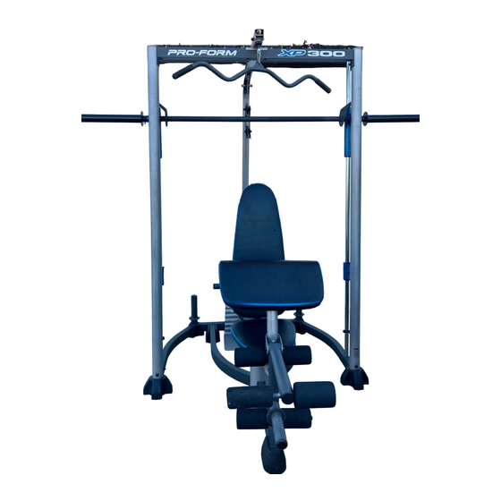
Model No. PFANBE3525.0
Serial No.
Write the serial number in the
space above for reference.
Serial Number Decal (under seat)
QUESTIONS?
As a manufacturer, we are
committed to providing com-
plete customer satisfaction.
If you have questions, or if
there are missing or dam-
aged parts, please call the
telephone number on the
warranty card accompanying
this manual or contact the
establishment where you pur-
chased this product.
CAUTION
Read all precautions and instruc-
tions in this manual before using
this equipment. Save this manu-
al for future reference.
USER'S MANUAL
Advertisement
Table of Contents

Related Manuals for ProForm PFANBE3525.0


Summary of Contents for ProForm PFANBE3525.0
- Page 1 Model No. PFANBE3525.0 Serial No. Write the serial number in the space above for reference. Serial Number Decal (under seat) QUESTIONS? As a manufacturer, we are committed to providing com- plete customer satisfaction. If you have questions, or if there are missing or dam-...
-
Page 2: Table Of Contents
If a decal is missing, call the telephone number on the warranty card accom- panying this manual and order a free replacement decal. Apply the decal in the location shown. PROFORM is a registered trademark of ICON IP, Inc. -
Page 3: Important Precautions
IMPORTANT PRECAUTIONS WARNING: To reduce the risk of serious injury, read the following important precautions before using the weight bench. 1. Read all instructions in this manual and all warnings on the weight bench before using the weight bench. Use the weight bench only as described in this manual. -
Page 4: Before You Begin
To help us assist you, please note the product model number and serial number before calling. The model number is PFANBE3525.0. The serial number can be found on a decal attached to the weight bench (see the front cover of this manual). -
Page 5: Assembly
ASSEMBLY Make Things Easier for Yourself Everything in this manual is designed to ensure that the weight bench can be assembled suc- cessfully by anyone. Most people find that set- ting aside plenty of time helps assembly go smoothly. Before beginning assembly, carefully read the following information and instructions: •... - Page 6 2. Attach the Bench Foot (15) to the Seat Base (1) with two M4 x 16mm Self-tapping Screws (91) and two M4 Washers (84). 3. Insert two M10 x 100mm Screws (26) up through the Base Plate (34), and the Seat Base (1), and the Right and Left Seat Bases (2, 3).
- Page 7 5. Attach the Backrest (11) to the Backrest Frame (8) with four M6 x 15mm Button Screws (17). 6. Grease the M10 x 87mm Button Bolt (94). Attach the Backrest Frame (8) to the Seat Frame (5) with the Bolt and an M10 Nylon Locknut (77). Do not overtighten the Locknut;...
- Page 8 8. Attach the Seat (12) to the Seat Frame (5) with four M6 x 63mm Button Screws (92) and four M6 Washers (81). 9. Insert a Pad Tube (10) into the Leg Lever (6). Slide two Foam Pads (14) onto the Pad Tube. Assemble the other two Pad Tubes (10) to the Leg Lever (6) and the Seat Frame (5) in the same manner.
- Page 9 11. Attach the Left Rack Base (37) to the Center Rack Base (39) with two M10 x 67mm Bolts (86), an M10 Washer (80), and an M10 Nylon Locknut (77). Do not tighten the Bolts. Repeat this step with the Right Rack Base (38). 12.
- Page 10 14. Insert the M10 x 20mm Bolt (89) into the Weight Carriage (42) from the side shown. Slide the Weight Carriage Stop (58) onto the Rear Upright (41). Slide the Weight Carriage (42) onto the Rear Upright. 15. Attach a Guide Rod (46) to the Left Rack Base (37) with an M8 x 53mm Bolt (9), two M8 Washers (83), an 11mm x 8mm Spacer (82), and an M8 Nylon Locknut (78).
- Page 11 17. Attach a Front Upright (43) to the Right Rack Base (38) with two M10 x 82mm Bolts (85), two M10 Washers (80), and an M10 Nylon Locknut (77). Do not tighten the Bolts. Attach the Front Upright (43) to the right Guide Rod (46) with an M10 x 25mm Bolt (88).
- Page 12 20. Orient the Locking Bar (50) as shown. Slide the Barbell (51) through the Left Barbell Guide (52), the Locking Bar, and the Right Barbell Guide (53). Make sure that the Barbell is centered in the Barbell Guides. Engage the Locking Bar into the Uprights (43) at the lowest position.
- Page 13 24. Route the Cable (61) under a Pulley (63). Attach the Pulley, a Cable Trap (66), and two Half Finger Guards (65) to the two Pulley Plates (35) with an M10 x 50mm Bolt (79) and an M10 Nylon Locknut (77).
-
Page 14: Adjustments
29. Attach the Cable (61) to the Rear Rack Base (40) with an M10 x 67mm Bolt (86), two M10 Washers (80), and an M10 Nylon Locknut (77). 30. Make sure that all parts are properly tightened. The use of the remaining parts will be explained in ADJUSTMENTS, starting below. - Page 15 ATTACHING ACCESSORIES The Lat Bar (55) can be attached to a Cable (61) with a Cable Clip (71). For some exercises the Chain (24) should be attached between the Cable and the Lat Bar with two Cable Clips. The other accessories can be attached to the Cables (61) in the same manner.
- Page 16 ADJUSTING THE BARBELL STOPS Hold the handle on the Barbell Stop Hook (48) and disengage the Hook from the Front Upright (43). Move the Barbell Stop (47) to the lowest point you want the Barbell (51) to go during the exercise. Reengage the Hook into the Upright.
-
Page 17: Cable Diagram
CABLE DIAGRAM The cable diagram shows the proper routing of the Cables (61). Use the diagrams to make sure that the cables and the cable traps have been assembled cor- rectly. If the cables have not been correctly routed, the weight bench will not function properly and dam- age may occur. -
Page 18: Exercise Guidelines
EXERCISE GUIDELINES THE FOUR BASIC TYPES OF WORKOUTS Muscle Building To increase the size and strength of your muscles, push them close to their maximum capacity. Your mus- cles will adapt and grow as you progressively increase the intensity of your exercise. You can adjust the inten- sity level of an individual exercise in two ways: •... - Page 19 Rest for a short period of time after each set. The ideal resting periods are: • Rest for three minutes after each set for a muscle building workout. • Rest for one minute after each set for a toning work- out.
-
Page 20: Part Identification Chart
PART IDENTIFICATION CHART Refer to the drawings below to identify small parts used in assembly. The number in parentheses by each draw- ing is the key number of the part, from the PART LIST in the center of this manual. Note: Some small parts may have been pre-attached. - Page 21 PART LIST—Model No. PFANBE3525.0 Key No. Qty. Description Seat Base Right Seat Base Left Seat Base Bumper Seat Frame Leg Lever Curl Post Backrest Frame M8 x 53mm Bolt Pad Tube Backrest Seat Curl Pad Foam Pad Bench Foot M8 x 20mm Button Screw...
- Page 22 EXPLODED DRAWING—Model No. PFANBE3525.0 R0406A...
- Page 23 EXPLODED DRAWING—Model No. PFANBE3525.0 R0406A...
-
Page 24: Ordering Replacement Parts
To help us assist you, be prepared to provide the following information: • the MODEL NUMBER of the product (PFANBE3525.0) • the NAME of the product (PROFORM XP 300 weight bench) • the SERIAL NUMBER of the product (see the front cover of this manual) •...