Advertisement
Quick Links
Advertisement

Related Manuals for Renegade RXA 550


Summary of Contents for Renegade RXA 550
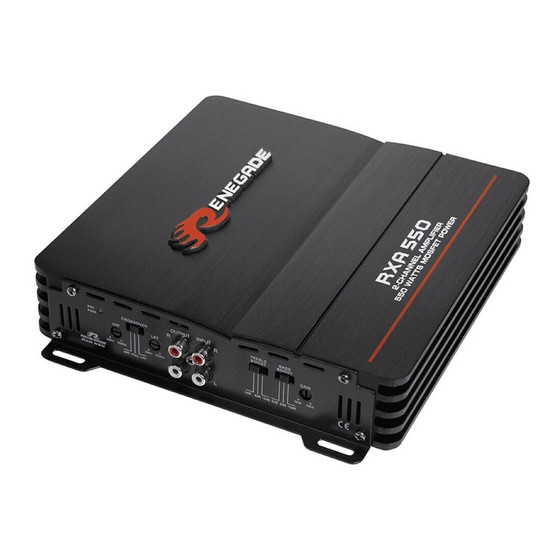
- Page 1 RXA 550 2-CHANNEL AMPLIFIER USER’S MANUAL...
-
Page 2: Specifications
Please read the user‘s manual carefully before the installation and the first operation of the amplifier. SPECIFICATIONS RXA550 Output Power RMS 2 x 75 W @ 4 Ohms 2 x 135 W @ 2 Ohms Output Power Max. 2 x 150 W @ 4 Ohms 2 x 275 W @ 2 Ohms Loudspeaker impedance (stereo) 2 –... - Page 3 IMPORTANT NOTES PRIOR TO INSTALLATION - This device is only suited for a 12 volt system with negative ground. - The radiated heat while operation requires sufficient air circulation at the place of installation. It is very important that the heatsink fins do not have contact with any metal parts or any surfaces which could impair air circulation. The amplifier may not be installed in small closed location or spaces without air circulation (e.g. spare wheel recess or below the vehicle carpeting). We recommend the installation in the vehicle’s trunk. Ensure sufficient protection against vibrations, dust and dirt. - Ensure that the input and output cables are sufficiently separated from the power supply cables. Otherwise interferences may occur.
-
Page 4: Input Sensitivity
AUDIO SIGNAL CABLES When installing the audio cables between the RCA outputs of the headunit and the RCA inputs of the amplifier, the audio and power supply cables should, if possible, not be routed along the same side of the vehicle. We recommend a separated installation, e.g. routing the power cable through the cable channel on the left side and the audio cables through the cable channel of the vehicle on the right side or vice versa. - Page 5 FIGURES (P. 28-30) CONNECTIONS AND CONTROLLERS (FIG. 1) (1) Power-/Protection-LED (2) Highpass filter controller (3) Selector FULL / LPF (Lowpass) / HPF (Highpass) (4) Lowpass filter controller (5) Audio signal outputs to supply additional amplifiers (6) Audio signal inputs (7) Bass Boost selector (8) Treble Boost selector (9) Gain controller POWER SUPPLY AND TURN ON CONNECTION (FIG.
-
Page 6: Troubleshooting
TROUBLESHOOTING If you are having problems after installation follow the Troubleshooting procedures below. Procedure 1: Check Amplifier for proper connections. Verify that PRT/PWR LED lits up green. If If this is the case, skip to Step 3, if not continue. 1. Check in-line fuse on battery positive cable. Replace if necessary. 2. - Page 7 –...
- Page 8 FULL 12dB 12dB 2 - 8 Ω 2 - 8 Ω...
- Page 9 12dB 4 - 8 Ω Learn more about car amplifiers on our website.