Extron electronics SW2 USB User Manual
Usb switchers, sw usb series
Hide thumbs
Also See for SW2 USB:
- Specifications (1 page) ,
- User manual (42 pages) ,
- Setup manual (4 pages)
Table of Contents
Advertisement
Quick Links
Advertisement
Table of Contents

Related Manuals for Extron electronics SW2 USB


Summary of Contents for Extron electronics SW2 USB
- Page 1 User Guide Switchers SW USB Series USB Switchers 68-1517-01 Rev. F 02 12...
- Page 2 Safety Instructions • English Warning Power sources • This equipment should be operated only from the power source indicated on the product. This This symbol is intended to alert the user of important operating and equipment is intended to be used with a main power system with a grounded (neutral) conductor. The third maintenance (servicing) instructions in the literature provided with the (grounding) pin is a safety feature;...
- Page 3 FCC Class A Notice This equipment has been tested and found to comply with the limits for a Class A digital device, pursuant to part 15 of the FCC Rules. Operation is subject to the following two conditions: This device may not cause harmful interference. This device must accept any interference received, including interference that may cause undesired operation.
-
Page 4: Conventions Used In This Guide
Selectable items, such as menu names, menu options, buttons, tabs, and field names are written in the font shown here: From the menu, select File Click the button. Copyright © 2012 Extron Electronics. All rights reserved. Trademarks All trademarks mentioned in this guide are the properties of their respective owners. -
Page 5: Table Of Contents
Contents Introduction SIS Programming and Control ............1 ......23 About this Guide ..........1 Host-to-Switcher Communications ....23 About the SW USB Series ........1 Switcher-initiated Messages ......23 Features .............. 1 Error Responses..........24 Application Diagrams .......... 2 Using the Command and Response Table .. - Page 6 SW USB Series • Contents...
-
Page 7: Introduction
• About this Guide This guide describes the Extron SW2 USB, SW4 USB, and SW4 USB Plus switchers and provides instructions on installing, configuring, and operating them. The terms “SW USB” and “switcher” are used throughout this guide to refer to all models. -
Page 8: Application Diagrams
RS-232 control and pass-through — The SW USB switcher can be controlled by • Simple Instruction Set (SIS ) commands received via an RS-232 interface. These SIS ™ commands can be sent to an RS-232 controllable Extron AV switcher attached to the “SIS Programming and Control”... - Page 9 Control System Extron with RS-232 SW4 USB -2 32 RS-232 -2 32 W IT RS-232 Loop-through A MA Visualizer Projector A rs M OT Laptop VGA Outputs Extron Annotator SW4 VGA Ars VGA/Audio Switcher Figure 2. Connection Diagram for an SW4 USB Switcher with an SW VGA Series Switcher in an Annotator Application Mouse Keyboard...
-
Page 10: Installation
Installation This section gives an overview of the steps to installing the SW USB Series switchers. It also provides a description of the rear panel connectors and instructions for cabling. The following topics are discussed: • Installation Overview • Rear Panel Features Wiring the Power Connector •... -
Page 11: Rear Panel Features
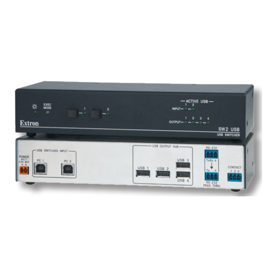
POWER CONTACT 0.7A MAX PC 1 PC 2 USB 1 USB 2 USB 4 RS-232 PASS THRU SW2 USB Rear Panel USB OUTPUT HUB RS-232 USB SWITCHED INPUT Tx Rx USB 3 POWER CONTACT 0.7A MAX PC 1 PC 2... -
Page 12: Wiring The Power Connector
Emulation DIP switches — (SW4 USB Plus only) These DIP switches enable host emulation to a keyboard and mouse connected to output ports 3 and 4. Switch 1 enables host emulation to a mouse; switch 2 enables emulation to a keyboard. When a keyboard or a mouse is connected to port 3 or 4, and the appropriate switch is set to On, the SW USB Plus switches to the connected keyboard or mouse instantly, without the delay that normally occurs while the computer recognizes a new peripheral... - Page 13 Use the supplied tie-wrap to strap the power cord to the extended tail of the connector. The figure below shows how to wire the power connector. Smooth Ridges SECTION A–A Power Supply Output Cord Tie Wrap 3/16” (5 mm) Max. Captive Screw Connector Figure 4.
-
Page 14: Wiring For Rs-232 Communication
Wiring for RS-232 Communication RS-232 Port The 3-pole, 3.5 mm captive screw connector labeled “RS-232” is used for optional RS-232 communication between the SW USB and a computer or control system. The control system plugged into this port can issue commands to the SW USB, which can pass the commands through to an Extron AV switcher that is plugged into the RS-232 Pass Thru port. -
Page 15: Rs-232 Pass Thru Port
RS-232 Pass Thru Port The RS-232 Pass Thru port loops the signal received at the SW USB RS-232 control port, the Contact (closure) port, or the front panel input buttons through the RS-232 Pass Thru port to send SIS commands to another Extron AV switcher. NOTE: Only Extron products can be controlled via this port. - Page 16 Figure 7 App Diagram Contact Closure -2 3 -2 3 RS-232 W IT Loop-through 1. 5A Extron Extron SW4 USB CCR 4BLB USB Switcher Controller Module 0 .2 0 -2 -6 0 Extron SW4 VGA Ars VGA/Audio Switcher Figure 7. Using the SW USB with a Contact Closure Device and an AV Switcher SW USB Series •...
-
Page 17: Connecting Multiple Sw Usbs In A System
Connecting Multiple SW USBs in a System The USB specification states that a maximum of five hubs (or five SW USBs) can be connected in a series. NOTE: Do not exceed five cascaded hubs and a total of 127 peripheral devices in the entire system. -
Page 18: Operation
Updating Firmware Front Panel Features ACTIVE USB EXEC INPUT MODE OUTPUT SW2 USB USB SWITCHER SW2 USB Front Panel ACTIVE USB EXEC INPUT MODE OUTPUT SW4 USB USB SWITCHER SW4 USB and SW 4 USB Plus Front Panel Figure 9. -
Page 19: Operations
Active USB (port status) LEDs: Input LEDs — Each of these green LEDs lights when a host or PC is connected to the corresponding USB input port on the switcher and is detected by the SW USB, whether or not the input is selected. Output LEDs —... -
Page 20: Issuing Commands To An Extron Av Switcher Via The Rs-232 Pass Thru Port
Selecting an input on an AV Switcher via contact closure To make input selections on a connected AV switcher via contact closure, you must place the SW USB in loop 0 mode. When the ground pin of the Contact port is connected to one of its other pins by by one of the methods described on the previous page, the SW USB sends the input selection SIS command X! (where X! is the input number) through... - Page 21 Mode SIS Command Commands Passed Through to an AV Switcher Loop 1 Only SIS commands received via the RS-232 control 1LOOP port Loop 0 • Input selections made via contact closure or the 0LOOP (Default Mode) front panel buttons • SIS commands sent via the RS-232 interface (loop 1 functionality) See the...
-
Page 22: Locking And Unlocking The Front Panel (Executive Mode)
Example: When a control system issues an SIS input selection command (select input 1), (select input 2), (select input 3), or (select input 4), the SW USB switches to the corresponding input.The SW USB also passes the SIS input selection command through the RS-232 Pass Thru port, causing the same input to be selected on the AV switcher. -
Page 23: Resetting
Resetting To reset the switcher to its factory default settings from the front panel: Disconnect power from the SW USB. Press and hold the Input 1 button while reapplying power to the unit. The Input LEDs blink three times to indicate that a reset has occurred. The input selection defaults to input 1, and the Input 1 LED lights. -
Page 24: Supported Peripheral Devices
NOTES: • If two mice or two keyboards are connected to output ports 3 and 4, and the appropriate emulation DIP switch is set to On, the switcher emulates a host to only one port. • When one or both DIP switches are set to On (up), host emulation follows the attached peripheral device: When the Mouse DIP switch (switch 1) is set to On (up), the switcher •... - Page 25 From the Start menu on your computer, select . The All Programs > Extron Electronics > Firmware Loader > Firmware Loader Firmware Loader window opens with the Add Device window in front of it. SW USB Series • Operation...
- Page 26 On the Add Device window, select your SW USB model from the Device Names drop-down menu. Figure 11. Device Name Drop-down Menu on the Add Device Window From the Connection Method drop-down menu, select RS-232 (the only option). Select the appropriate options from the menus (this Com Port Baud Rate...
- Page 27 NOTES: • The original factory-installed firmware is permanently available on the SW USB. If the attempted firmware upload fails for any reason, the switcher reverts to the factory-installed firmware. • When downloaded from the Extron website, the firmware is placed in a folder at C:\Program Files\Extron\Firmware\SW USB C:\Program Files (x86)\Extron\Firmware\SW USB...
- Page 28 Click Begin. The following indicators on the Firmware Loader window show the progress of the update: The Transfer Time section shows the amounts of remaining and elapsed time for the • update. The Total Progress section displays a progress bar with above it.
-
Page 29: Sis Programming And Control
The switcher sends the following copyright message when it first powers on. © Copyright 20nn, Extron Electronics SWn USB [Plus], Vn.nn where is the switcher model number as well as the number of inputs, and is the Vn.nn... -
Page 30: Error Responses
Error Responses If the switcher is unable to execute a command it receives because the command is invalid or contains invalid parameters, the SW USB returns an error response to the host. Error response codes and their descriptions are: – Invalid input channel number (out of range) –... -
Page 31: Command And Response Table For Sis Commands
Command and Response Table for SIS Commands ASCII Command Response Command Additional Description (Host to Unit) (Unit to Host) Input Selection X! ] Select input Select input for both the SW USB and the attached AV switcher (if any). = 1, 2, 3, or 4. X! ] Select SW USB input Select input... - Page 32 ASCII Command Response Command Additional Description (Host to Unit) (Unit to Host) Upload Firmware Upl appears after the upload is complete Upload firmware Upload ...go (see “Updating Firmware” in the “Operation” section for information on the firmware updating process). SW USB Series • SIS Programming and Control...
-
Page 33: Reference Information
Contact closure pin configuration SW2 USB ......... 1 = input 1, 2 = input 2, 3 = GND SW4 USB, SW4 USB Plus ..1 = input 1, 2 = input 2, 3 = input 3, 4 = input 4, 5 = GND Program control ...... - Page 34 Temperature/humidity ....Storage: -40 to +158 °F (-40 to +70 °C) / 10% to 90%, noncondensing Operating: +32 to +122 °F (0 to +50 °C) / 10% to 90%, noncondensing Cooling .......... Convection, no vents Thermal dissipation Device ........29.4 BTU/hr Device and power supply ..
-
Page 35: Part Numbers And Accessories
SW4 USB Plus 60-954-02 3.5 mm, 3-pole captive screw connector with strain relief 100-456-01 (3 for SW2 USB, 2 for SW4 USB and SW4 USB Plus) 3.5 mm, 5-pole captive screw connector with strain relief 100-457-01 (SW4 USB and SW4 USB Plus) -
Page 36: Mounting The Sw Usb Series Switcher
Mounting the SW USB Series Switcher The SW USB Series switcher can be set on a table, mounted on a rack shelf, or mounted under a desk, podium, or table. Tabletop Use Four adhesive rubber feet are included with the SW USB switcher. For tabletop use, attach one foot at each corner on the bottom of the unit, and place the switcher in the desired location. -
Page 37: Furniture Mounting
HalfRackVersaToolsShelf Diagrams VersaTools Rack Shelf 1/2 Rack Width Front False Faceplate Use 2 mounting holes on (2) 4-40 x 3/16" opposite corners. Screws Figure 17. Mounting an SW USB Switcher on a 3.5-inch Deep Rack Shelf 1U Universal Rack Shelf 1/2 Rack Width Front False Faceplate Front false... - Page 38 Insert #8 wood screws into the four pilot holes. Tighten each screw into the mounting surface until slightly less than 1/4 inch of the screw head protrudes. Align the mounting screws with the slots in the brackets and place the unit against the surface, with the screws through the bracket slots.
-
Page 39: Extron Warranty
Extron Electronics makes no further warranties either expressed or implied with respect to the product and its quality, performance, merchantability, or fitness for any particular use. In no event will Extron Electronics be liable for direct, indirect, or consequential damages resulting from any defect in this product even if Extron Electronics has been advised of such damage.