Table of Contents
Advertisement
Advertisement
Table of Contents

Related Manuals for FUTABA Mega Tech 3PK


Summary of Contents for FUTABA Mega Tech 3PK
- Page 1 1M23N11002 Digital Proportional R/C System...
-
Page 2: Application, Export And Reconstruction
Trade Control Regulations. An application for export approval must be submit- ted. 3. Modification, adjustment and replacement of parts. Futaba is not responsible for unauthorized modification, adjustment and re- placement of parts of this product. THE FOLLOWING STATEMENT APPLIES TO THE RECEIVER (FOR U.S.A.) - Page 3 -No part of this manual may be reproduced in any form without prior permission. -The contents of this manual are subject to change without prior notice. -This manual has been carefully written, please write to Futaba if you feel that any corrections or clarifica- tions should be made.
- Page 4 Table Of Contents For Your Safety As Well As That Of Others ..Explanation of Symbols ................... High Response System (H.R.S) Precautions ..........Operation Precautions ..................Nicad Battery Handling Precautions .............. Storage and Disposal Precautions ..............Other Precautions ..................Before Using ............Features ......................
- Page 5 Subtrim ....................Channel Reverse .................. Fail Safe/Battery Fail Safe (HRS/PCM Mode Only) ......Model Select ..................Model Reset ..................For Your Safety As Well As Model Copy ................... That Of Others Model Name ..................Function Select Dial ................Function Select Switch ................ Dual Rate/Second Dual Rate ..............
-
Page 6: Explanation Of Symbols
For Your Safety As Well As That Of Others Use this product in a safe manner. Please observe the following safety precautions at all times. Explanation of Symbols The parts of this manual indicated by the following symbols are extremely important and must be observed. -
Page 7: Operation Precautions
Operation Precautions Warning Prohibited Procedures Do not operate two or more models Do not operate in the following on the same frequency at the same places. time. -Near other sites where other radio control activity may occur. Operating two or more models at same time on the same frequency will cause interference and loss of -Near people or roads. - Page 8 Caution Prohibited Procedures Do not touch the engine, motor, speed control or any part of the model that will generate heat while the model is operating or immediately after its use. These parts may be very hot and can cause serious burns. Mandatory Procedures Turning on the power switches.
-
Page 9: Nicad Battery Handling Precautions
Nicad Battery Handling Precautions (Only when Nicad batteries are used) Warning Mandatory Procedures Always check to be sure your batter- To recharge the transmitter Nicad , ies have been charged prior to oper- use the special charger made for this ating the model. -
Page 10: Storage And Disposal Precautions
Storage and Disposal Precautions Warning Prohibited Procedures Mandatory Procedures Do not leave the radio system or When the system will not be used for models within the reach of small chil- any length of time store the system dren. with batteries in a discharged state. Be sure to recharge the batteries prior A small child may accidentally operate the system, to the next time the system is used. -
Page 11: Other Precautions
The fuel, motor spray, waste oil and exhaust will pen- Futaba will not be responsible for problems caused by etrate and damage the plastic. the use of other than Futaba genuine parts. Use the parts specified in the instruction manual and catalog. -
Page 12: Before Using
- High Response System (H.R.S. system) When used with the H.R.S. system, a speed of triple that of an FM system at average response is realized. (Comparison with other Futaba products) The T3PK transmitter compatible with the H.R.S. system, PCM1024 system, and PPM (FM) system. - Page 13 - Start function (AT-START) When the throttle trigger is set to full throttle simultaneously with starting on slippery roads, the wheels spin and the vehicle does not accelerate (start). Setup the start function allows smooth starting. - Steering speed (ST-SPEED) "When you sense that the steering servo is too fast, etc., the servo operating speed (direction that suppresses the maximum speed) can be adjusted.
-
Page 14: Set Contents
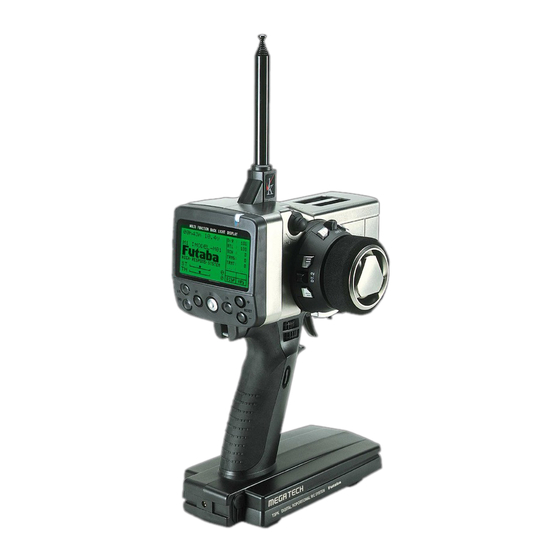
Always use only genuine Futaba transmitter, receiver, FET amp, Ni-cad battery and other optional parts. Futaba will not be responsible for damage caused by other than genuine Futaba parts and components. Use only the genuine Futaba parts and components listed in the instruction manual and catalog. - Page 15 Transmitter T3PK Nomenclature Antenna LCD screen Pilot lamp (See page 16 for the operating instructions.) Steering trim (DT1) Digital trim 3 (DT3) CH3 knob ( DL3) (See page 16 for the operating instructions.) Edit buttons (See page 16 for the operating instructions.) Throttle trim Power...
-
Page 16: Digital Trim Operation
Digital Trim Operation (Initial settings: DT1: Steering trim, DT2: Throttle trim, DT3: -------) Operating by the lever: Push the lever to the left or right (up or down). Operating by push button switch: Press the push button switch in the desired direc- tion. -
Page 17: Mechanical Atl Adjustment
Mechanical ATL Adjustment Make this adjustment when you want to make the throttle trigger brake (back) side stroke narrower. Adjustment Using a Phillips screwdriver, adjust the trigger brake (back) side stroke by turning the screw through the adjusting hole indi- cated by the arrow in the figure. -
Page 18: Battery Replacement
Battery Replacement Battery cover 1. Slide the transmitter battery cover in the arrow direction while pressing the part shown in the figure. 2. Replace the Ni-cad battery pack or Dry cell batteries. 3. Slide the battery cover back onto the transmitter. While pressing this part. -
Page 19: Charging The Ni-Cad Battery
AC outlet Charging the Ni-cad Battery Charging Charger 1. Plug the transmitter cord of the special charger into the charg- ing jack on the rear of the trans- Transmitter charging mitter. 2. Plug the charger into an AC out- Cord to transmit- let. -
Page 20: Handling The Rf Module
Handling the RF module RF module cover Removing the RF module 1 Remove the RF module cover by slid- ing it in the arrow direction. 2.Pull the module upward while pushing the left and right claws to the inside. Inserting the RD module 1 Insert the module while being careful that the transmitter side connector pins are not bent. -
Page 21: Set Data Backup
When inserting and removing the data pack Always turn off the transmitter power before removing or inserting the data pack. Data pack initialization When using the data pack, initialization is necessary so MEMORY MODULE that the data pack can be used with this transmitter. When INITIALIZE ? "INITIALIZE?"... -
Page 22: Display When Power Switch Turned On
User name display When the (END) button is held down for 1 second or longer at the initial screen, the Futaba logo and user name are displayed for about 2 seconds. Total timer The total timer shows the accumulated time from last reset. -
Page 23: Lcd Screen Contrast
LCD Screen Contrast The LCD screen contrast can be adjusted. (For more information, see page .) Caution Do not adjust the contrast so that the LCD is too bright or too dark. When the display cannot be read due to a temperature change, data cannot be set. LCD Screen Temperature Change In the following cases, the LCD may become difficult to read due to a temperature change. -
Page 24: Steering Wheel
Removing the steering wheel unit 1. After removing the wheel cap, 4. Remove the wheel unit cover. carefully remove the screw Be very careful the wheel holding the steering wheel. shaft will fall out. 2. Remove the steering wheel. 5. Remove the 4 screws from the wheel unit. - Page 25 Changing wheel position 2. Reinstall the wheel unit, 1. Connect the wheel unit con- wheel unit cover, wheel, and nector through the offset wheel cap in same position adapter. Install the adapter as they were removed. using four 2.5mm hex bolts at- tached.
- Page 26 Receiver Nomenclature Crystal When changing the frequency, use the Antenna specified Futaba crystal set. Connectors 1: Steering servo (CH1) 2: Throttle servo (CH2) 3: CH3 servo (CH3) R113iP B/C: Power connector/DSC connector receiver Crystal Antenna When changing the frequency, use the specified Futaba crystal set.
-
Page 27: Receiver And Servo Connections
Installation Receiver and Servo Connections When connecting and installing the receiver and servos, read the “Installation Safety Precautions” on the next page. Installation When An FET Amp Is Used (MC800CFET Amp) Installation For Gas Powered Models... -
Page 28: Installation Safety Precautions
Installation Safety Precautions Warning Connector Connections Electronic speed control Be sure the receiver, servo, crystal Install the heat sinks where they will and connectors are fully and firmly not come in contact with aluminum, connected. carbon fiber or other parts that con- duct electricity. -
Page 29: Initial Setup
If signals are output normally, RF output monitor "RF" will be displayed on the screen. If RF is not displayed, check if the transmitter crystal and RF module are installed. If the transmitter is abnormal or faulty, contact your Futaba dealer. "RF"... -
Page 30: Trims Initial Set-Up
2. Modulation Mode Check The T3PK transmitter output signal format can be changed to match the type of receiver. Check if the modulation mode is set to match the receiver used. When using an FM receiver (e.g., R133F), the modula- tion mode must be set to PPM. - Page 31 - Steering dual rate (DL1) check At initial set-up, steering dual rate is assigned to grip dial DL1 (upper) at the grip of the transmitter. Operate the DL1 dial and check if the D/R value displayed on the screen changes. After checking D/R, set the steer- ing dual rate to 100%.
-
Page 32: Function Map
Function Map Menu Selection The function set-up screen can be easily selected from the function menu displayed on the LCD screen. The function menu can be selected from among the following 3 levels to match the level of use. To select the level, use the Level Select function (page ). -Level 3 (LV3): All functions can be selected. -
Page 33: Direct Selection
Direct Selection The Direct Selection allows instant access to the six functions most frequently used. The function set-up screen can be directly and quickly called with the special buttons for each function of the six functions, they can be freely selected as the Direct Selec- tion Button function. - Page 34 Functions End point adjuster/EPA (All channels) Use this when performing steering left and right steering angle adjustments, throttle high side/brake side operation amount adjustment, and channel 3 servo up side/down side operation amount adjustment during linkage. - Corrects the maximum steering angle and left and right steering angles when there is a difference in the turning radius due to the characteristics, etc.
- Page 35 Calling the setup screen Use the button to * Calling from menu screen select the setup item. (Initial screen) blinks at the current setup item. Use the Setup items button to select the ST-LFT : Steering (left side) MENU menu screen. ST-RGT : Steering (right side) TH-FWD : Throttle (forward side) Press the...
- Page 36 Throttle steering angle (EPA) adjustment (Preparation) - Before setting the throttle steering angle, set the throttle 100% ATL dial (initial setup: DL2) to the maximum steering angle position 100%. - Select setup item "TH-FWD" and make the following adjustments: 1 Throttle (forward side) adjustment Setup item switching Pull the throttle trigger fully to the high side and use - Use the (DN) and (UP) buttons to...
- Page 37 Steering EXP/ST-EXP (Steering system) This function is used to change the sensitivity of the steering servo around the neutral position. It has no effect on the maximum servo travel. Racers Tip When the setting is not determined, or the characteristics of the model are unknown, start with 0%.
-
Page 38: Operation
Steering Speed/ST-SPEED (Steering system) Quick steering operation will cause momentary understeering, loss of speed, or spin- ning. This function is effective in such cases. Smooth cornering Spin Understeering Steering speed not set Steering speed set Operation - This function limits the maximum speed of TURN direction the steering servo. - Page 39 Steering Speed (ST-SPEED) adjustment (Preparation) - Select setup item "TURN" and make the following ad- justments: 1 "TURN" direction adjustment Setup item switching - Use the (DN) or (UP) button to switch Use the (+) and (-) buttons to adjust the delay the setup item.
- Page 40 Throttle EXP/TH-EXP (Throttle system) This function makes throttle trigger high side and brake side direction servo opera- tion quicker or milder. It has no effect on the servo maximum operation amount. For the high side, selection from among three kinds of curves (EXP/VTR/CRV) is also possible.
- Page 41 when you want to quicker the rise and use the (- ) button to adjust the - side when you want to make the rise milder. 3 When ending adjustment, return to the initial screen by pressing the (END) button 3 times. Adjustment method for VTR curve (Preparation) - Select "VTR"...
- Page 42 TG.P=50% TG.P=20% TG.P=80% 100% 100% 100% +1%∼+100% +1%∼+100% +1%∼+100% -1%∼ -100% -1%∼ -100% -1%∼ -100% Adjustment method for CRV curve (Preparation) Adjustment range 1: ~ 5: 0 ~ 100% - Select "CRV" at setup item "FWD-TYP". FWD-TYP : EXP, VTR, CRV BRK-EXP : -100 ~ 0 ~ +100% Setup items Adjustment buttons...
-
Page 43: Throttle Curve
Throttle curve 100% Initial value 初期値 (ノーマルカーブ) (normal curve) Initial values P1 : 17% 設 P2 : 33% 定 P3 : 50% 値 P4 : 67% P5 : 83% 設定例 Example スティックポイント Trigger point... -
Page 44: Switch Setting
Throttle speed/TH-SPEED (Throttle system) Sudden trigger operation on a slippery road only causes the wheels to spin and the vehicle cannot ac- celerate smoothly. Setting the throttle speed func- TH-SPEED/Smooth, quick starts possible tion reduces wasteful battery consumption while at the same time permitting smooth, enjoyable opera- tion. - Page 45 Throttle speed adjustment (Preparation) - Select setup item "MODE" and make the following ad- justments: 1 (Function ON/OFF) Set the throttle speed function to the "ACT" state Function ON/OFF: INH(OFF), ACT(ON), ACT(OFF) by pressing the (+) or (-) button. "INH(OFF)" : Function OFF "ACT(ON)"...
- Page 46 When the A.B.S. function is activated, the LED flashes. Fail Safe Unit When the 3PK is used with the Futaba fail safe unit (FSU-1), it will operate as de- scribed below. - When the FSU-1 is connected to the throttle channel, and the A.B.S. function has been activated, the FSU-1 LED will flash each time the servo operates.
- Page 47 Calling the setup screen Setup items Use the button to ABP : Brake return amount * Calling from menu screen select the setup item. (Initial screen) DLY : Delay amount blinks at the current CYC : Cycle speed setup item. Use the MODE : Function ON/Off button to select the...
- Page 48 4 (Cycle speed adjustment) Select setup item "CYC" by pressing the (DN) Cycle speed 1 ~ 30 button once and use the (+) and (-) buttons to Initial value; 10 adjust the speed. - The lower the set value, the faster the cycle speed. 5 (Operation point setup) Select set item "TGP"...
- Page 49 Example of A.B.S. function setting when S9402 used (There will be a slight difference depending on the state of the linkage.) - Basic setting AB.P: Approx. 30% (If this value is too high, the braking distance will increase.) CYCL: 5~7 DUTY: 0 (When grip is low: - side, when grip is high: + side) DLY: 10~15% TG.P: Approx.