
Related Manuals for FUTABA 6EX-2.4GHZ


Summary of Contents for FUTABA 6EX-2.4GHZ
- Page 1 6EX-2.4GHz INSTRUCTION MANUAL for Futaba 6EX-2.4GHz 6-channel, FASST Radio control system for Airplanes/Helicopters Futaba Corporation Technical updates available at: http://www.futaba-rc.com Entire Contents © Copyright 2007 1M23N12014...
-
Page 2: Table Of Contents
HOLD Throttle hold function ........25 Glossary................4 REVO Pitch - rudder mixing function ......26 GYRO Gyro mixing function.........26 Introduction to the 6EX-2.4GHz system ......5 SW-T Swash to throttle mixing........28 Transmitter controls and descriptions ......5 SWSH Swashplate types selection & Swash AFR..28 Radio installation ..............7... -
Page 3: Introduction
“non-computer” radio. Although this is a beginner or sport system with the requirements of those flyers in mind, in order to make the best use of your Futaba 6EX-2.4GHz and to operate it safely, you must carefully read all of the instructions. -
Page 4: Contents And Specifications
Throw can also refer to the distance a servo arm (or wheel) travels. Dual rate (D/R) - On the 6EX-2.4GHz the dual rate switch allows you to instantly switch, in flight, between two different control throws for the aileron, elevator and rudder. Often, different control throws are required for different types of flying. -
Page 5: Introduction To The 6Ex-2.4Ghz System
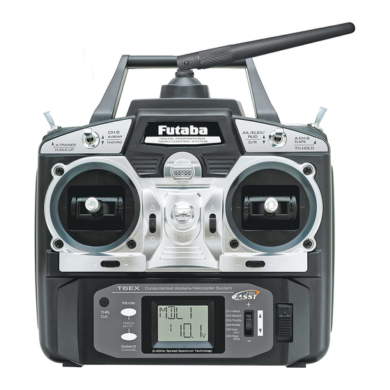
HELI mode: Dual rate (D/R), Idle up, Throttle hold, and Gyro sense can be operated by switch. Two different gyro senses can be set with Futaba GY401/502/611 Gyro on gyro function of this transmitter. Programming features include servo reversing and E.P.A on all channels, dual rates, exponentials, throttle curve, pitch curve, throttle hold, and pit to rudder mixing(REVO). - Page 6 H:Gyro switch/Channel 5 - You can connect the sense adjust connector to channel 5 of the receiver to operate the gyro, which has two different senses. Also if you use the Futaba GY401/502/611 Gyro, two different gyro sense settings on the gyro function in this transmitter can be called by this switch.
-
Page 7: Radio Installation
• Note the small numbers (1, 2, 3, 4) molded into each arm on the Futaba 4-arm servo arms. The numbers indicate how many degrees each arm is “off” from 90 degrees to correct for minute manufacturing deviations from servo to servo. - Page 8 • IMPORTANT: Since the 2.4GHz have different characteristics than that of the conventional 27MHz and 72MHz frequencies, please read this section carefully to enjoy safe flight with the 2.4GHz system. Receiver's Antenna Installation: • The R606FS has two antennas. These antennas have a diversity function to decrease the chance of a receiving error.
- Page 9 Transmitter Antenna 1. The transmitter antenna is adjustable so please make sure that the antenna is never pointed directly at the model when flying as this creates a weak signal for the receiver. 2. Keep the antenna perpendicular to the transmitter's face to create a better RF condition for the receiver.
-
Page 10: Receiver And Servo Connections
RECEIVER AND SERVO CONNECTIONS Connect the servos to the receiver to perform the functions indicated: Receiver Function output Aircraft (ACRO) Helicopter (HELI) channel Aileron -or-right flaperon -or-right elevon (for tail- Aileron less models) Elevator -or-left ruddervator (for V-tail models) Elevator -or-left elevon (for tailless models) Throttle Throttle... -
Page 11: Charging The Nicd Batteries
If there is a noticeable drop in capacity the batteries should be replaced. Note: Charging your batteries with the included Futaba A/C battery charger is always safe. However, fast-charging with an aftermarket charger is acceptable as long as you know how to properly operate the charger. NEVER charge at a rate... -
Page 12: Lcd And Programming Controls
Model name The Futaba T6EX-2.4GHz stores model memories for six models. This means all the data (control throws, trims, end points, etc.) for up to six different models can be stored in the transmitter and activated at any time (depending upon which model you choose to fly that day). - Page 13 NOT turn off the power during the initialization; otherwise initialization will restart when you turn on the power. Do not fly when this message is displayed: all programming has been erased and is not available. Return your transmitter to Futaba service.
-
Page 14: Programming The T6Ex-2.4Ghz Radio
PROGRAMMING THE 6EX-2.4GHz RADIO Anytime you wish to view or change any of the current settings in the transmitter, the programming mode must first be entered by, of course, turning on the power, then by pressing the “MODE” and “SELECT” keys simultaneously and holding them down for one second. -
Page 15: Acro/Heli Model Type Select Function
ACRO/HELI Model type select function The Model type select function is used to select the ACRO or HELI mode of model type. ACRO: Powered aircraft memory type (with multiple wing and tail configurations. See Wing mixing type selection for further information, p20.) HELI: Helicopter memory type (with three helicopter swashplate type. -
Page 16: Model Name Settings
Model name function Assign a name to the model memory. By giving each model a name that is immediately recognizable, you can quickly select the correct model, and minimize the chance of flying wrong model memory that could lead to a crash. To assign a name 1. -
Page 17: Expo Exponentials
the throw. 5. Repeat the procedure for the other dual rate (channel 2-elevator, 4-rudder). EXPO Exponential Settings The “exponentials” are in the same function as the dual rates. (Pressing the MODE key will take you to the next function which is End Point Adjustments). -
Page 18: Trim Trim Settings
TRIM Trim Settings There are four trim levers (“trims”) on the front of the transmitter. Three of the trims are for adjusting the neutral position of the aileron, elevator and rudder servos. The fourth trim is for setting the idle r.p.m. of the engine when the throttle stick is all the way down. -
Page 19: (Acro Functions) Pmx1 Programmable Mixer #1
PMIX1/2 Programmable Mixer 1/2 (ACRO only) Unlike the “wing mixing” function (explained later) where the channels to be mixed are factory-set, the T6EX-2.4GHz also contains two programmable mix where you, the pilot determine the channels to be mixed. This could be used to correct unwanted flight tendencies (by mixing rudder to aileron, or aileron to rudder for example). -
Page 20: Flpr Flaperon Mixing
Wing Mixing Type Selection (ACRO only) With the programmable mix (previously described) the user determines the two channels to be mixed. The wing mixing function is another mix that may be used, but the channels mixed are predetermined. There are three different wing mixing functions to select from: FLPR Flaperon mixing (ACRO only) This function allows the ailerons to be used both as ailerons and as flaps. -
Page 21: V-Tl V-Tail Mixing
To activate flap trim: 1. Enter the programming mode. Access the “FLTR” screen with the MODE key. 2. If “INH” is blinking, push DATA INPUT lever upward for 0.5 seconds. Then you will see that the blinking “INH” changes to “ON”. Your flap trim is now turned on. 3. -
Page 22: Elvn Elevon Mixing
4. Next you may set the elevator. Press the SELECT key to display the “CH2” and flashing “%” sign. Use the DATA INPUT lever to set the percentage of elevator travel rate from -100% to +100% 5. Next you may set the rudder. Press the SELECT key to display the “CH4” and flashing “%” sign. - Page 23 3. Push the DATA INPUT lever upward for 0.5 seconds. This will cause the flashing “INH” display to change to a flashing “ON” display. Now the mixing is on. 4. Next you set the left wing to channel 1 (aileron) setting. Press the SELECT key to display the “CH1”...
-
Page 24: N-Th Normal Throttle Curve
N-TH Normal throttle curve function (HELI only) Used to set throttle curve for normal flight. 5-point throttle curve is utilized to best match the blade collective pitch to the engine RPM for consistent load on the engine. Throttle curve can be adjusted from 0-100% each point. This normal throttle curve creates a basic curve for hovering. -
Page 25: I-Pi Idle-Up Pitch Curve Function
3. Use SELECT key to select the desired curve point. Point 1 is shown initially which is throttle stick’s all the way downward (slow) position. Point 5 is throttle stick’s all the way upward (hi) position. 4. Push up or down DATA INPUT lever to set the servo position. 5. -
Page 26: Revo Pitch - Rudder Mixing Function
REVO Pitch-rudder mixing function (HELI only) This mix adds rudder in conjunction with pitch. This helps compensate for rotation of the helicopter caused by the increased engine torque. (Never use revo. mixing with a heading-hold/AVCS gyro which is in heading hold/AVCS mode. However, revo. mixing is still used when a heading-hold/AVCS gyro is in normal mode.) To set the REVO mixing: 1. - Page 27 specialized digital servos. Examples: • GY401: Simpler set up. Ideal for learning aerobatics through 3D. • GY502: Better centering than 401 for more advanced aerobatics. Ideal through Class III competition. • GY611: Exceptional center. Extremely fast response time. Requires specialized servo. Gyro mixing function is used for adjusting the gain of the gyro.
-
Page 28: Sw-T Swash To Throttle Mixing
SW-T Swash to throttle mixing (HELI only) This function corrects slowing of engine speed caused by swashplate operation at aileron or elevator operation. To activate swash to throttle mixing: 1. Enter the programming mode. Access the “SW-T” screen with the MODE key. 2. - Page 29 To select the swashplate types: 1. Enter the programming mode and use the MODE key to access the “SWSH” function. 2. To select swashplate type press the DATA INPUT lever upward or downward for about two seconds. When you are changing swashplate type to 1-S, 3-S or 3-E, the 1-S, 3-S or 3-E on the display flashes slow, becomes rapid, and then returns slow flashing with confirmation sound.
-
Page 30: Fs Fail Safe (Throttle Channel Only)
F/S Fail Safe (Throttle channel <ch 3> only) The Fail Safe function is recommended to use for safety reasons in the event of radio interference. In this menu, you may select from one of two options. The “NOR”(normal) setting holds the servo in its last commanded position, while the “F/S”(Fail Safe) function moves the servo to a predetermined position. -
Page 31: Flow Chart (Acro)
FLOW CHART ACRO MODE FUNCTIONS Stick Mode To change the Stick Mode, turn on the transmitter and hold the (Screen at Startup) MODE and SELECT keys down To enter or leave Programming Mode, simultaneously. press MODE and SELECT keys simultaneously for one second. Use the DATA INPUT lever to display the desired stick mode. -
Page 32: Flow Chart (Heli)
FLOW CHART HELI MODE FUNCTIONS Stick Mode To change the Stick Mode, turn on the transmitter and hold the (Screen at Startup) MODE and SELECT keys down To enter or leave Programming Mode, simultaneously. press MODE and SELECT keys simultaneously for one second. Use the DATA INPUT lever to display the desired stick mode. -
Page 33: Othert6Ex-2.4Ghz Functions
(29-72MHz) 5. With the transmitters off, connect the trainer cord to both radios. (On the 6EX-2.4GHz the trainer jack is in the center of the rear of the case.) Do not force the plug into the transmitter and note that the plug is “keyed” so it can go in only one way. -
Page 34: Adjustable-Length Control Sticks
When the length is suitable, lock the stick in position by turning locking piece B counterclockwise. Changing the 6EX-2.4GHz stick mode The transmitter may be operated in four different stick “modes” (1, 2, 3 & 4). The modes determine the functions that will be operated by control sticks. -
Page 35: Flight Preparation
FLIGHT PREPARATION Flight preparation is to be done at the flying field. If you are an inexperienced pilot, be certain your flight instructor performs these following checks with you. Check the controls 1. Get the frequency clip from the frequency control board at your flying site if the site has a clip for 2.4GHz. 2. -
Page 36: Model Data Recording Sheets (Acro)
MODEL DATA RECORDING SHEET (ACRO) (Make copies before using) Model name: Model No. 1• 2 • 3 • 4 • 5 • 6 Model Type: ACRO MENU FUNCTION CH 1 CH 2 CH 3 CH 4 CH 5 CH 6 REVR •... -
Page 37: Model Data Recording Sheets (Heli)
MODEL DATA RECORDING SHEET (HELI) (Make copies before using) Model name: Model No. 1• 2 • 3 • 4 • 5 • 6 Model Type: HELI MENU FUNCTION CH 1 CH 2 CH 3 CH 4 CH 5 CH 6 REVR •... - Page 38 FUTABA CORPORATION Makuhari Techno Garden Bldg., B6F 1-3 Nakase, Mihama-ku, Chiba 261-8555, Japan Phone: (043) 296-5119 Facsimile: (043) 296-5124 ©FUTABA CORPORATION 2007, 02...