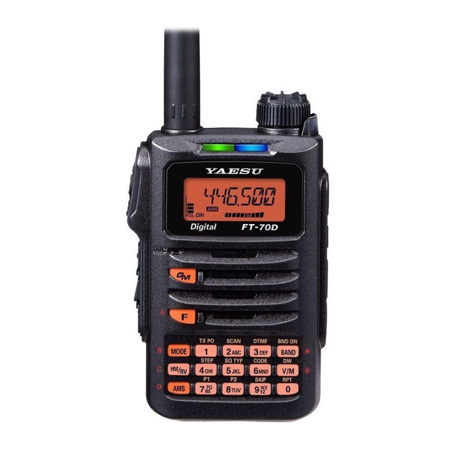
Yaesu FT-70DR Operating Manual
C4fm/fm 144/430mhz
digital/analog transceiver
Hide thumbs
Also See for FT-70DR:
- Advance manual (47 pages) ,
- Operating manual (6 pages) ,
- Instruction manual (32 pages)
Table of Contents
Advertisement
Quick Links
Advertisement
Table of Contents

Related Manuals for Yaesu FT-70DR


Summary of Contents for Yaesu FT-70DR
- Page 1 C4FM/FM 144/430MHz DIGITAL/ANALOG TRANSCEIVER FT-70D FT-70D Operating Manual...
-
Page 2: Table Of Contents
Contents Introduction .............. 1 VFO Scan ..............27 Memory Channel Scanning ........27 Quick Guide ............. 2 Setting the Receive Operation When Scanning Stops ... 28 Controls & Connections ......... 3 Weather Alert Scan ..........28 Transceiver ............... 3 Skip Memory Channel and Specified Memory Channel ... 29 The Keypad Functions .......... -
Page 3: Introduction
We urge you to read this manual in its entirety, and also the Advance Manual ( available for down- load on the Yaesu website ) , to gain a full understanding of the amazing capability of the exciting new FT-70DR/FT-70DE Transceiver. -
Page 4: Quick Guide
) switch to conclude z Transmitting inputting. While pressing and holding the PTT ( Normal operation ( VFO Mode ) screen switch, speak into the microphone. will be displayed z Receiving Release the to return to receive mode. FT-70DR/FT-70DE Operating Manual... -
Page 5: Controls & Connections
When the power is ON, press and hold the switch again to turn the Power OFF. • When the power is ON, press this button briefly to engage, or release the key lock. Battery pack* ( 12 ) FT-70DR/FT-70DE Operating Manual... - Page 6 12 ) *: When the included antenna and battery pack are installed and the MIC/SP jack, DATA terminal, and EXT DC IN jack are securely covered with rubber caps, the FT-70DR/DE meets the water- proofing performance conforming to IP54. FT-70DR/FT-70DE Operating Manual...
-
Page 7: The Keypad Functions
“?”, or “!” on inputting the frequency. during repeater operation. *: VW icon is displayed when Set Mode [ 16 DIG VW ] ( 36 ) is set to “ON” ( the default setting is “OFF” ) . FT-70DR/FT-70DE Operating Manual... -
Page 8: Display
Appears when the PAGER function is enabled. The battery condition is displayed in 4 steps. ( No display ) ׃Full battery power ׃Enough battery power ׃Battery is depleted. Charge battery. ( ׃When blinking ) Charge battery immediately. FT-70DR/FT-70DE Operating Manual... - Page 9 Appears when the bell function in the analog FM mode is enabled. Appears when the lock function is enabled. V/D mode ( Normal digital mode ) Voice FR mode ( Voice wide mode ) Analog FM mode AM mode ( Receive only ) DTMF Autodialer Active – FT-70DR/FT-70DE Operating Manual...
-
Page 10: Safety Precautions ( Be Sure To Read )
Be sure to read these important precautions, and use this product safely. Yaesu is not liable for any failures or problems caused by the use or misuse of this product by the pur- chaser or any third party. Also, Yaesu is not liable for damages caused through the use of this product by the purchaser or any third party, except in cases where ordered to pay damages under the laws. - Page 11 Do not use DC power cords other than the product or Yaesu Amateur Customer Support. one enclosed or specified. Do not bend, twist, pull, heat and modify This may result in fire, electric shock and the power cord and connection cables in equipment malfunctions.
- Page 12 DATA terminal when water drops have accumulated on the transceiver, or when it is placed in a wet environment. This may result in water penetrating the transceiver, and caus- ing equipment failure. This product is not totally waterproof, and must never be immersed in water. FT-70DR/FT-70DE Operating Manual...
-
Page 13: About This Manual
Availability of accessories may vary. Some accessories are supplied as standard to meet local re- quirements, while others may be unavailable in some regions. Consult your Yaesu Dealer for de- tails regarding these and any newly-available options. Connection of any accessory not approved by Yaesu, should it cause damage, may void the Limited Warranty on this apparatus. -
Page 14: Preparation
Removing the Battery Pack 1. Slide the battery pack lock plate to the “UNLOCK” position. Unlock 2. Push the release button ( PUSH ) and tilt the Belt Clip outward, and then remove the battery pack. FT-70DR/FT-70DE Operating Manual... -
Page 15: Charging The Battery Pack
Connecting to an External Power Supply Using a Power Cable The optional DC cable ( E-DC-6 ) allows the transceiver to be connected to an external DC power supply. FT-70DR/FT-70DE Operating Manual... -
Page 16: Operation
Characters that may be inputted for the call sign are the numbers 0-9, letters ”A – Z” in upper case, the hyphen and the slash. Adjusting the Volume Level 1. While pressing and holding the VOL knob, rotate the DIAL knob to adjust the volume to a comfortable level. FT-70DR/FT-70DE Operating Manual... -
Page 17: Adjusting The Squelch Setting
2. Press the PTT switch to save the setting and return to normal operation. In the default setting, of the frequency step is set to “AUTO”, which automatically provides a suitable frequency step according to the frequency band. FT-70DR/FT-70DE Operating Manual... -
Page 18: Selecting The Communication Mode
Selecting the Communication Mode Using AMS ( Automatic Mode Select ) function The FT-70DR/DE transceiver is equipped with the AMS ( Automatic Mode Select ) func- tion which automatically selects the communication mode corresponding to the received signal. 1. Press and hold the [ AMS ] key to turn the AMS function ON or OFF. -
Page 19: Fixing The Communication Mode
As a result, the transmitting power level is automatically set to Low Power. If transmission continues while the high temperature protection function is active, the transceiver will be forcibly returned to the receive mode. FT-70DR/FT-70DE Operating Manual... -
Page 20: Changing The Transmission Power Level
The [ 7 ] ( P1 ) is [ 12 DC VLT ] ( 36 ) and [ 8 ] ( P2 ) key is [ 47 RX MOD ] ( 37 ) as a default assignment. FT-70DR/FT-70DE Operating Manual... -
Page 21: Using The Convenient Digital C4Fm Feature
2. When accessing the C4FM digital repeater controlled by the DG-ID number, set the transmit DG-ID number of the FT-70DR/DE to that of the repeater input. Even in that case, if the receive DG-ID number of the FT-70DR/DE is set to “00”, all the downlink signals from the repeater may be received. -
Page 22: Communicating Only With The Specific Members By Setting The Dg-Id Number Except For "00
If the receive DG-ID is set to a number other than “00”, only signals with that DG-ID will be received. Normally, set the receive DG-ID number to “00” except when communication is desired only with group members. FT-70DR/FT-70DE Operating Manual... -
Page 23: About The Gm ( Group Monitor ) Feature
GM information screen (Automatically switching display) Group Mode Display Own DG-ID Number Display Memory Tag Display Frequency Display :Memory tag display is displayed in the case of the memory channel or the home channel setting the memory tag. FT-70DR/FT-70DE Operating Manual... -
Page 24: Displaying The Information Of The Other Station Received By Gm ( Group Monitor ) Function
LCD. • Up to 24 stations may be displayed in order of their reception. z The FT-70DR/DE may not send its own location information because the FT-70DR/DE is not equipped with the GPS function. -
Page 25: Repeater Operation
T-CALL switch, and use the PTT switch to activate the transmitter thereafter. If needed, the FT-70DR ( USA/Asian version ) , may be set to access repeaters which re- quire a 1750 Hz burst tone by setting the MONI/T-CALL switch to serve as a “Tone Call”... -
Page 26: Using The Memory
For additional details on the Skip Search Memory, PMS memory channel and Memory Bank, refer to the Advanced Manual which may be downloaded from the Yaesu website. CAUTIONS! The information registered to memory channels can be corrupted by incorrect operation, static electricity, or electrical noise. -
Page 27: Registering To Memory Channels
10 memory channels. z The transceiver may be placed into a Memory Channel Only mode, ( which restricts the FT-70DR/DE to operate only on the memory channels ) , by pressing the [ V/M ] key, while pressing the Power ( Lock ) switch to turn the transceiver ON. -
Page 28: Clearing Memories
The beep sounds and the home channel frequency is changed. For additional details on the following functions, refer to the Advanced Manual which may be downloaded from the Yaesu website. Split Memory Two different frequencies, one for receive and another for transmit, can be registered to a memory channel. -
Page 29: Scanning Function
• Weather Alert Scan For additional details on the Programmable Memory Scan ( PMS ) and Memory Bank Scan, refer to the Advanced Manual which may be downloaded from the Yaesu website. VFO Scan VFO scan function scans the frequencies, and detects signals. -
Page 30: Setting The Receive Operation When Scanning Stops
NOAA Alert Tone while operating using VFO scan or Memory channel scan. When the Weather Alert Scan feature is engaged, the FT-70DR/DE will check the Weather Broadcast Channels for activity every five seconds while scanning. If you watch... -
Page 31: Skip Memory Channel And Specified Memory Channel
163.275 MHz For additional details on the following functions, refer to the Advanced Manual which may be downloaded from the Yaesu website. Skip Memory Channel and Specified Memory Channel Two types of memory channels may be designated, “skip memory channels” and “speci- fied memory channels”... -
Page 32: Using The Wires-X Function
You may employ Internet communications by connecting from your transceiver to a WIRES-X local node station. FT-70DR/DE does not accommodate the transmission/reception of messages, images, audio messages, or location information. Connecting to a WIRES-X node in the C4FM mode (*Recommended) z Ascertain the DSQ code or the DG-ID setting of the WIRES-X node station. - Page 33 (the C0 screen) Most recent connected node ID or room ID is dis- played. A single press of the [AMS] key or PTT switch while this screen is displayed, will connect to the most recent node/room. FT-70DR/FT-70DE Operating Manual...
- Page 34 (C0 / C1 - C5 / En screen*) (*The PTT switch is disabled on the En screen) Press and hold the [BAND] key Disconnect from the connected node or room. (Lc / Cn / C0 / C1 - C5 / En Screen) FT-70DR/FT-70DE Operating Manual...
-
Page 35: Connect And Communicate With Wires-X In Analog Mode
8. When communication is completed, press and hold the [MODE] key to exit WIRES-X mode. z About WIRES-X open node stations A listing of the WIRES-X open node stations, with their location, operation mode, etc. is posted on the Yaesu WIRES-X website. https://www.yaesu.com/jp/en/wires-x/index.php Connect and communicate with WIRES-X in analog mode Confirm that the node station setting is in analog mode. -
Page 36: Convenient Functions
Convenient Functions For additional details on the following functions, refer to the Advanced Manual which may be downloaded from the Yaesu website. Tone squelch feature The tone squelch opens the speaker audio only when a signal containing the specified CTCSS tone is received. By matching the tone frequency with the partner station in ad- vance, a quiet standby is possible. -
Page 37: Using Set Mode
On some setting screens, key operation is different than described in the above steps ( For example, inputting the characters, etc. ) . Refer to the Advance manual. For additional details, refer to the Advanced Manual which may be downloaded from the Yaesu website. Display and Key Lamp Dimmer The illumination level of the display and keys may be adjusted from the six levels. -
Page 38: Tables Of Set Mode Operations
OFF / 2 SEC – 5 SEC – 10 SEC / CONT keys to be lit. ( LED lights up ) LED.LGT Turn ON the LED light. LOCK Configure the lock mode setting. KEY / DIAL / K+D / PTT / K+P / D+P / ALL FT-70DR/FT-70DE Operating Manual... - Page 39 Turn the weather alert scan on/off. OFF / ON WIDE / NARROW W/N.DEV Set the Transmit Modulation Level. W-DGID Setting of the WIRES-X DGID AUTO / DGID01 – DGID99 ( up to 10 characters ) MYCALL Set the call sign. FT-70DR/FT-70DE Operating Manual...
-
Page 40: Restoring To Defaults ( Reset )
38 PAG.CDR 39 PAG.CDT 41 PSWDWT 44 RF SQL 46 RPT.FRQ 47 RX MOD 49 SCM.WTH 50 SCV.WTH 54 SQL.EXP 62 W/N.DEV 64 MYCALL To cancel the resetting, press any key except the [ F ] key. FT-70DR/FT-70DE Operating Manual... -
Page 41: Specifications
At least 50 dB below ( @TX Power Low ) European version At least 60 dB below ( @TX Power High, Middle ) At least 55 dB below ( @TX Power Low ) Microphone Impedance: 2 kΩ FT-70DR/FT-70DE Operating Manual... -
Page 42: Eu Declaration Of Conformity
Frequency ranges will vary according to transceiver version; check with your dealer. EU Declaration of Conformity We, Yaesu Musen Co. Ltd of Tokyo, Japan, hereby declare that this radio equipment FT-70DE is in full compliance with EU Radio Equipment Directive 2014/53/EU. The full text of the Declaration of Conformity for this product is available to view at http://www. - Page 43 Changes or modifications to this device that are not expressly approved by YAESU MUSEN could void the user’s authorization to operate this device. z This device complies with part 15 of the FCC Rules. Operation is subject to the following two conditions: ( 1 ) This device may not cause harmful interference, and ( 2 ) this device must accept any interference including received, interference that may cause undesired operation.