
Related Manuals for Danfoss AKD 5001


Summary of Contents for Danfoss AKD 5001
- Page 1 Refrigeration and Air Conditioning Controls Catalogue Electronic controls AKD 5000 ® ADAP-KOOL Refrigeration control systems...
-
Page 2: Table Of Contents
AKD 5000 Contents Safety ........................3 Safety regulations ..................... 4 Warning against unintended start ................4 Quick Setup ......................6 AKD Lon card ......................8 Introduction ....................... 10 Ordering form AKD 5000 Series - Typecode ............11 Technical data ....................12 General technical data .................... - Page 3 AKD 5000 PID for process control ................... 54 Quick discharge ..................... 55 Flying start ......................56 Normal/high overload torque control, open loop ............. 57 Programming of Torque limit and stop ..............58 Programming ....................59 Operation and Display .................... 59 Parameters —...
-
Page 4: Safety
AKD 5000 AKD 5000 Series Operating instructions Software version: 1.6x These operating instructions can be used for all AKD 5000 Series frequency converters with software version 1.6x. The software version number can be seen from parameter 624. MG.50.R3.02 -... -
Page 5: Safety Regulations
AKD 5000 The voltage of the frequency converter is dangerous whenever the equipment Warning against unintended start is connected to mains. Incorrect 1. The motor can be brought to a stop by installation of the motor or the frequency converter means of digital commands, bus commands, may cause damage to the equipment, serious references or a local stop, while the frequency... - Page 6 AKD 5000 Warning: It can be extremely dangerous to touch the electrical parts even when the mains supply has been disconnected. Also ensure that other voltage inputs are disconnected from load sharing through the DC bus. Wait at least 4 minutes after the input power has been removed before servicing the drive.
-
Page 7: Quick Setup
AKD 5000 Quick Setup Introduction to Quick Setup This Quick Setup will guide you through EMC correct installation of the frequency converter by connecting power, motor and control wiring (fig. 1). Start/stop of motor is to be done with the switch. Fig. - Page 8 AKD 5000 2. Electrical Installation, power NOTE: The terminals are detachable on AKD 5001-5006, 200-240 V and AKD 5001-5011, 380-500 V Connect the mains supply to the mains terminals L1, L2, L3 of the frequency converter and to the earth connection (fig.
-
Page 9: Akd Lon Card
AKD 5000 3. Electrical installation, control leads Use a screw driver to remove the front cover under the control panel. NOTE: The terminals are detachable. Connect a jumber between terminals 12 and 27 (Fig. 10) Mount screened cable to external start/stop of control terminals 12 and 18. - Page 10 AKD 5000 AKD Lon connections: A 6-pole connector (only 1-4 is used) that connects The Lon card has two connections. to the AKD. Connections are as follows: AKD-Connections: Lon card terminals (Red +24V) (White or Yellow (Black Com) (Green TX+, RX+) TX-, RX-) AKD terminals 39 or 20...
-
Page 11: Introduction
AKD 5000 Introduction These Operating Instructions are a tool intended for persons who are to install, operate and program the AKD 5000 Series. When reading these Operating Instructions, you will come across different symbols that require special attention. The symbols used are the following: Indicates a general warning NB!: Indicates something to be noted by the reader... -
Page 12: Ordering Form Akd 5000 Series - Typecode
AKD 5000 Ordering form AKD 5000 Series - Typecode MG.50.R3.02 -... -
Page 13: Technical Data
Switching on output ..........................Unlimited Ramp times ............................ 0.05-3600 sec. Torque characteristics: Starting torque, AKD 5001-5027, 200-240 V and AKD 5001-5062, 380-500 V ......160% for 1 min. Starting torque ..........................180% for 0.5 sec. Acceleration torque ............................100% Overload torque, AKD 5001-5027, 200-240 V and AKD 5001-5062, 380-500 V .......... 160% Arresting torque at 0 rpm (closed loop) ...................... - Page 14 AKD 5000 Accuracy on input ......................Max. error 1% of full scale Scanning time per input ..........................3 msec. Terminal no. ground ............................55 Reliable galvanic isolation: All analogue inputs are galvanically isolated from the supply voltage (PELV) as well as other inputs and outputs. Control card, pulse/encoder input: No.
- Page 15 /16 AWG If UL/cUL is to be complied with, cable with temperature class 60/75°C must be used (AKD 5001-5062 380-500 V and AKD 5001-5027 200-240 V). Accuracy of display readout (parameters 009-012): Motor current [6] 0-140% load ............... Max. error: ±2.0% of rated output current Torque % [7], -100 - 140% load ..............
- Page 16 AKD 5000 Externals: Enclosure ............................. IP 20, IP 54 Vibration test ........0.7 g RMS 18-1000 Hz random. 3 directions for 2 hours (IEC 68-2-34/35/36) Max. relative humidity ................93 % (IEC 68-2-3) for storage/transport Max. relative humidity ..........95 % non condensing (IEC 721-3-3; class 3K3) for operation Aggresive environment (IEC 721 - 3 - 3) ..................
-
Page 17: Electrical Data
AKD 5000 Electrical data Compact, Mains supply 3 x 200 - 240 V According to international requirements A A A A K K K K D D D D t t t t y y y y p p p p e e e e 5 5 5 5 0 0 0 0 0 0 0 0 1 1 1 1 5 5 5 5 0 0 0 0 0 0 0 0 2 2 2 2 5 5 5 5 0 0 0 0 0 0 0 0 3 3 3 3... - Page 18 Always comply with national and local regulations on min. cable cross-section. 5. Aluminium cables with cross-section above 35 mm must be connected by use of a AI-Cu connector. 6. If UL/cUL is to be complied with, Ferraz Shawmut type Y85443, Danfoss ordering no. 612Z1182 must be used. MG.50.R3.02 -...
- Page 19 AKD 5000 Compact, Mains supply 3 x 380 - 500 V According to international requirements A A A A K K K K D D D D t t t t y y y y p p p p e e e e 5 5 5 5 0 0 0 0 0 0 0 0 1 1 1 1 5 5 5 5 0 0 0 0 0 0 0 0 2 2 2 2 5 5 5 5 0 0 0 0 0 0 0 0 3 3 3 3...
- Page 20 AKD 5000 Compact, Mains supply 3 x 380 - 500 V According to international requirements A A A A K K K K D D D D t t t t y y y y p p p p e e e e 5 5 5 5 0 0 0 0 0 0 0 0 5 5 5 5 5 5 5 5 0 0 0 0 0 0 0 0 6 6 6 6 5 5 5 5 0 0 0 0 0 0 0 0 8 8 8 8...
- Page 21 4. Min. cable cross-section is the smallest cable cross-section allowed to be fitted on the terminals to comply with IP 20. Always comply with national and local regulations on min. cable cross-section. 5. If UL/cUL is to be complied with, Ferraz shawmut type FA Y85443, Danfoss ordering no. 612Z1182 must be used. MG.50.R3.02 -...
- Page 22 Always comply with national and local regulations on min. cable cross-section. 5. Aluminium cables with cross-section above 35 mm must be connected by use of a AI-Cu connector. 6. If UL/cUL is to be complied with, Ferraz shawmut type FA Y85443, Danfoss ordering no. 612Z1182 must be used. MG.50.R3.02 -...
-
Page 23: Fuses
A6KR fuses from FERRAZ SHAWMUT may substitute A2KR for 240 V drives. A50X fuses from FERRAZ SHAWMUT may substitute A25X for 240 V drives. Non UL compliance If UL/cUL is not to be complied with, we recommend the above mentioned fuses or: AKD 5001-5027 200-240 V type gG AKD 5001-5062... -
Page 24: Mechanical Dimensions
AKD 5000 Mechanical dimensions All the below listed measurements are in mm. ab/be Type Compact IP 20 5001 - 5003 200 - 240 V 5001 - 5005 380 - 500 V 5004 - 5006 200 - 240 V 5006 - 5011 380 - 500 V 5008 200 - 240 V 5016 - 5022 380 - 500 V 5011 - 5016 200 - 240 V... - Page 25 AKD 5000 Type F, IP54 MG.50.R3.02 -...
-
Page 26: Installation
For the unit to be able to release its cooling Compact w/IP 4x top cover air, the minimum distance over and below the unit AKD 5001-5006 200 V must be as shown in the illustration below. AKD 5001-5011 500 V... - Page 27 AKD 5000 Installation of AKD 5001-5062 All frequency converters must be installed in a Side by side/flange by flange way that ensures proper cooling. All frequency converters can be mounted side Cooling by side/flange by flange. All units require a minimum space above and below the enclosure.
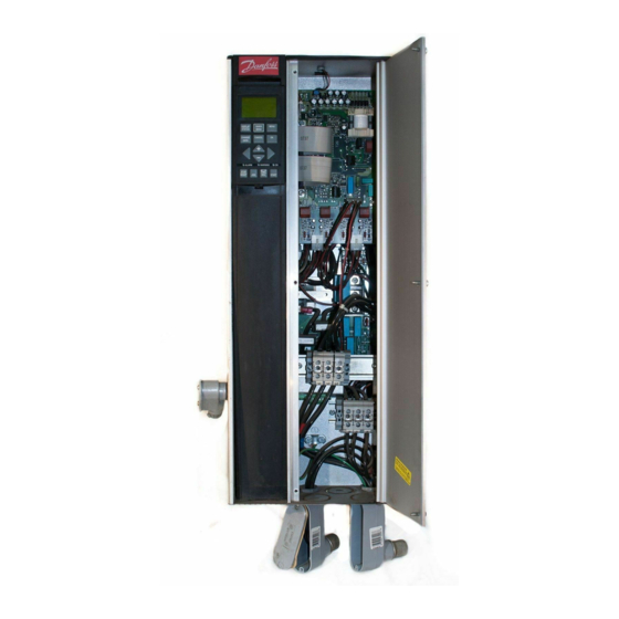
- Page 28 Touching the electrical parts may be fatal, even after the mains supply has been disconnected. Using AKD 5001-5006, 200-240 V and 380-500 V: wait at least 4 minutes. Using AKD 5008-5052, 200-240 V: wait at least 15 minutes.
- Page 29 AKD 5000 Compact IP 54 AKD 5001-5006, 200-240 V AKD 5001-5011, 380-500 V MG.50.R3.02 -...
- Page 30 AKD 5000 Compact IP 20 / IP 54 AKD 5001-5006 200-240 V AKD 5001-5011 380-500 V Compact IP 20 AKD 5008-5027 200-240 V AKD 5016-5062 380-500 V MG.50.R3.02 -...
- Page 31 AKD 5000 Compact IP 20 AKD 5008-5027 200-240 V AKD 5016-5062 380-500 V Compact IP 54 AKD 5008-5027 200-240 V AKD 5016-5062 380-500 V Compact IP 54 AKD 5008-5027 200-240 V AKD 5016-5062 380-500 V MG.50.R3.02 -...
-
Page 32: Electrical Installation - Emc Precautions
AKD 5000 Electrical installation - EMC precautions The illustration shows an example of an EMC-correct The following is a guideline to good engineering electrical installation of an IP 20 frequency converter; practice, when installing drives. Following these the frequency converter has been fitted in an installation guidelines is advised, where compliance with EN cabinet with an output contactor and connected 50081, EN 55011 or EN 61800-3 First environment is... - Page 33 AKD 5000 MG.50.R3.02 -...
-
Page 34: Electrical Installation, Selection Of Emc-Correct Cables
Twisted copper wire or armoured steel wire cable. Single-layer braided copper wire with varying percentage screen coverage. This is the typical Danfoss reference cable. Double-layer braided copper wire. Twin layer of braided copper wire with a magnetic, screened/armoured intermediate layer. -
Page 35: Electrical Installation - Earthing Of Control Cables
AKD 5000 Electrical installation - earthing of control cables Generally speaking, control cables must be braided Correct earthing screened/armoured and the screen must be Control cables and cables for serial communication connected by means of a cable clamp at both must be fitted with cable clamps at both ends to ends to the metal cabinet of the unit. -
Page 36: Electrical Installation - Mains Supply
NB!: terminals to the frequency converter. For AKD The frequency converter has a high leakage 5001-5027 200-240 V, AKD 5001-5062 380-500 V current and must be earthed appropriately the cables must be fastened with screws. for safety reasons. Use earth terminal... - Page 37 AKD 5008 200 - 240 V AKD 5016 - 5022 380 - 500 V Compact IP 20/NEMA 1 AKD 5001 - 5006 200 - 240 V AKD 5001 - 5011 380 - 500 V Compact IP 20/NEMA 1 AKD 5011 - 5016 200 - 240 V AKD 5027 - 5032 380 - 500 V MG.50.R3.02 -...
- Page 38 Compact IP 54 Compact IP 54 AKD 5016 - 5027 200 - 240 V AKD 5001 - 5006 200 - 240 V AKD 5032 - 5062 380 - 500 V AKD 5001 - 5011 380 - 500 V MG.50.R3.02 -...
-
Page 39: Electrical Installation - Motor Cables
AKD 5000 Electrical installation - motor cables Direction of motor rotation NB!: If an unscreened cable is used, some EMC requirements are not complied with, see the Design Guide. If the EMC specifications regarding emission are to be complied with, the motor cable must be screened, unless otherwise stated for the RFI filter in question. -
Page 40: Electrical Installation - Brake Cable
AKD 5000 In systems with motors connected in parallel, the electronic thermal relay (ETR) of the frequency converter cannot be used as motor protection for the individual motor. Consequently, additional motor protection is required, such as thermistors in each motor (or individual thermal relays) suitable for frequency converter use. -
Page 41: Electrical Installation - Bus Connection
AKD 5000 Electrical installation - external fan supply Torque 0,5-0,6 Nm DIP Switches 1-4 Screwsize: M3 The dipswitch is located on the control card. It is used for serial communication, terminals 68 and 69. The switching position shown is the factory setting. Switch 1 has no function. - Page 42 AKD 5000 Function 1 1 1 1 2 2 2 2 , , , , 1 1 1 1 3 3 3 3 Voltage supply to digital inputs Tightening-up torque: 0.5-0.6 Nm For the 24 V DC to be usable Screw size: M3 for the digital inputs, switch 4 on See section earthing of braided screened/armoured...
- Page 43 AKD 5000 Electrical installation Conversion of analogue inputs Current input signal to voltage input 0-20 mA ⇒ 0-10 V Connect 510 ohms resistor between input terminal 4-20 mA ⇒ 2-10 V 53 and 55 (terminal 54 and 55) and adjust minimum and maximum values in parameters 309 and 310 (parameters 312 and 313).
-
Page 44: Operation Of The Akd
AKD 5000 Control panel (LCP) The front of the frequency converter features a control panel - LCP (Local Control Panel), which makes up a complete interface for operation and monitoring of the AKD 5000 Series. The control panel is detachable and can - as an alternative - be installed up to 3 metres away from the frequency converter, e.g. -
Page 45: Control Panel - Control Keys
AKD 5000 If certain threshold values are exceeded, the alarm and/or warning LED lights up together with a status [OK] is used for confirming a change of the and alarm text on the control panel. parameter selected. The voltage LED is activated when the frequency converter receives voltage, or 24 V external supply;... - Page 46 AKD 5000 Display mode O O O O p p p p e e e e r r r r a a a a t t t t i i i i n n n n g g g g v v v v a a a a r r r r i i i i a a a a b b b b l l l l e e e e : : : : U U U U n n n n i i i i t t t t : : : : In normal operation, up to 4 different operating Reference...
-
Page 47: Quick Setup
AKD 5000 a choice between two programming modes - a Menu mode and a Quick menu mode. 24.3% 30.2% 13.8A The former provides access to all parameters. The 50.0 Hz latter takes the user through a few parameters which make it possible in most cases to start operating the frequency converter. -
Page 48: Parameter Selection
AKD 5000 Parameter selection G G G G r r r r o o o o u u u u p p p p n n n n o o o o ..P P P P a a a a r r r r a a a a m m m m e e e e t t t t e e e e r r r r g g g g r r r r o o o o u u u u p p p p : : : : The selection of parameter is effected by means of the Operation &... -
Page 49: Initialisation To Factory Setting
AKD 5000 Changing of data value, step-by-step The bottom display line shows the text value that will be entered (saved) when acknowledgement is given [OK]. Certain parameters can be changed step by step or infinitely variably. This applies to Motor power (parameter 102), Motor voltage (parameter 103) and Motor frequency (parameter 104). - Page 50 AKD 5000 • Press the following keys at the same time: [Display/status] [Change data] [OK] • Reconnecting the mains supply while pressing the keys. • Release the keys • The frequency converter has now been programmed for the factory setting. This parameter initialises all except: 600-605 Operating data...
- Page 51 AKD 5000 Menu structure DISPLAY MODE VAR 1.1 VAR 1.2 VAR 1.3 VAR 2 STATUS MENU MODE QUICK MENU MODE FREQUENCY QUICK MENU 1 OF 13 50.0 HZ 50.0 HZ KEYB.&DISPLAY 001 LANGUAGE ENGLISH Choice of Choice of parameter group DATA MODE FREQUENCY 50.0 HZ...
-
Page 52: Application Configuration
AKD 5000 Application configuration There is a choice of the following configurations: Using this parameter enables the choice of a - Speed control, open loop configuration (setting) of the frequency converter - Speed control, closed loop that fits the application in which the frequency - Process control, closed loop converter is to be active. -
Page 53: Special Functions
AKD 5000 Automatic Motor Adaptation, AMA Automatic motor adaptation is a test algorithm How to perform an AMA that measures the electrical motor parameters at 1. Press the [STOP/RESET] key a motor standstill. This means that AMA itself 2. Set motor nameplate data in parameters 102 to 106 does not supply any torque. - Page 54 ‘Continue’ or ‘Stop’. INTERNAL FAULT [7] An internal fault has occurred in the frequency converter. Contact your Danfoss supplier. LIMIT VALUE FAULT [8] The parameter values found for the motor are outside the acceptable range within which the frequency converter is able to work.
-
Page 55: Pid For Process Control
AKD 5000 PID for process control Relative references can be programmed. A relative Feedback reference is a percentage value (Y) of the sum of The feedback signal must be connected to a terminal the external references (X). This percentage value on the frequency converter. -
Page 56: Quick Discharge
AKD 5000 less than 1.6 Hz. Choose a suitable time constant in intermediate circuit voltage has dropped to a given parameter 444, Process PID Lowpass filter. value and the rectifier has stopped. In order to obtain the possibility of a quick discharge, Optimisation of the process controller the frequency converter requires an external 24 V DC The basic settings have now been made;... - Page 57 AKD 5000 a quick discharge of the intermediate circuit voltage NB!: will be carried out after the motor has stopped. The frequency converter can be completely damaged if the Quick-discharge function Using a digital input, it is possible to activate mains is repeated, using the digital input while failure and/or quick discharge.
-
Page 58: Flying Start
AKD 5000 Flying start the DC brake is active via parameters 125 and 126. If This function makes it possible to "catch" a motor Both directions is selected, the frequency converter will that is spinning freely and for the frequency converter first find out in which direction the motor rotates and to take control of the motor speed. -
Page 59: Programming Of Torque Limit And Stop
AKD 5000 to 1 min. in both CT and VT. This function is used mainly for pumps and fans, since these applications Description: do not require an overload torque. If a stop command is active via terminal 18 and the frequency converter is not at the torque limit, The advantage of choosing a normal torque the motor will ramp down to 0 Hz. -
Page 60: Programming
AKD 5000 Operation and Display 5. An external control command that can be connected to terminal 16, 17, 19, 27, 29, 32 or 33. However, [2] or [4] must be selected in parameter 013. 001 Language (LANGUAGE) See also section Shift between local and remote control. Value: English (ENGLISH) German (DEUTSCH) - Page 61 AKD 5000 Setup 3 (SETUP 3) NB!: Setup 4 (SETUP 4) If a general change of data or a copying to MultiSetup (MULTI SETUP) the active Setup is effected, this immediately affects the functioning of the unit. Function: This parameter defines the Setup number to control the functions of the frequency converter.
- Page 62 AKD 5000 Select Download all parameters [2] if all transmitted Analogue input 53 [V] (ANALOG INPUT 53 [V]) [17] parameter values are to be copied to the frequency Analogue input 54 [V] (ANALOG INPUT 54 [V]) [18] converter on which the control panel has been mounted. Analogue input 60 [mA] Select Download power-independent par.
- Page 63 AKD 5000 Output energy [kWh] states the energy Warning word 1. [Hex] indicates one or consumed by the motor since the latest reset more warnings in a Hex code. See page 160 was made in parameter 618. for further information. Motor voltage [V] states the voltage supplied Warning word 2.
- Page 64 AKD 5000 LCP digital control/as parameter 100. Shift from Remote control to LCP control/as parameter (LCP+DIG CTRL/AS P100) 100 or LCP digital control/as parameter 100. The present reference will be maintained. If the reference Function: signal is negative, the local reference will be set at 0. This is where the desired function is to be selected if Local control has been chosen in parameter 002.
- Page 65 AKD 5000 018 Lock for data change (DATA CHANGE LOCK) Value: Not locked (NOT LOCKED) Locked (LOCKED) Function: In this parameter, the software can "lock" the control, which means that data changes cannot be made via LCP (however, this is still possible via the serial communication port).
-
Page 66: Parameters - Load And Motor
AKD 5000 Parameters — Load and motor Normal-variable torque with high constant starting torque (N-VT HIGH W. CT-START) 100 Configuration Function: (CONFIG. MODE) In this parameter, the principle for adjusting the U/f Value: characteristics of the frequency converter to the Speed control, open loop torque characteristics of the load is selected. - Page 67 AKD 5000 Function: 5.5 kW (5.50 KW) [550] 7.5 kW (7.50 KW) Select a value that equals the nameplate [750] 11 kW (11.00 KW) data on the motor. [1100] 15 kW (15.00 KW) [1500] NB!: 18.5 kW (18.50 KW) [1850] The motor will always see the peak voltage, 22 kW (22.00 KW) [2200]...
- Page 68 AKD 5000 Description of choice: For 87 Hz operation with 230/400 V motors, set the nameplate data for 230 V. Adapt parameter The rated motor speed n is used i.a. for calculating 202 Output frequency high limit and parameter 205 the optimal slip compensation.
- Page 69 AKD 5000 NB!: NB!: It is important to set motor parameters If the setting in parameter 102-109 is changed, 102-106 correctly, since these form part of the parameters 110-118 will return to factory the AMA algorithm. In most applications, setting. If using special motor characteristics a correct entering of motor parameters 102-106 is change in parameter 102-109 affects parameter 422.
- Page 70 AKD 5000 113 Load compensation at low speed Motor size Change-over (LO SPD LOAD COMP) 0.5 kW - 7.5 kW >10 Hz Value: 11 kW - 45 kW >5 Hz 0 - 300 % 100 % 55 kW - 355 kW >3-4 Hz Function: This parameter enables compensation of voltage in...
- Page 71 AKD 5000 Function: 125 DC braking current Here it is possible to select the function of the frequency (DC BRAKE CURRENT) converter after a stop command or when the frequency Value: has been ramped down to 0 Hz. See parameter 123 50 % with respect to activation of this parameter regardless of whether the stop command is active.
- Page 72 AKD 5000 Description of choice: Select ETR Trip 1-4 if tripping is desired when the motor is overloaded according to the calculations. Set the desired frequency. The frequency converter can also be programmed to give off a warning signal via one of the digital outputs, in which case the signal is given both for 128 Motor thermal protection warning and for trip (thermal warning).
-
Page 73: Parameters - References And Limits
Set the desired value. which the motor is to run. The factory setting is 60 The unit follows the choice of configuration Hz for AKD 5001-5062 380-500 V, AKD 5001-5062 in parameter 100. 550-600 V and 5001-5027 200-240 V. Speed control, open loop: Speed control, closed loop: See also parameter 205. - Page 74 AKD 5000 the rated motor speed n (if Speed control, closed External/preset (EXTERNAL/PRESET) [ 2] loop has been selected in parameter 100). This Function: presupposes that the output current does not reach It is possible to define how the preset references the torque limit (to be set in parameter 221).
- Page 75 AKD 5000 See drawings in section Handling of multi-references. 221 Torque limit for motor mode (TORQ LIMIT MOTOR) Value: 0.0 % - xxx.x % of T 160 % of T Function: This function is relevant for all application configurations; speed, process and torque control. This is where to set the torque limit for motor operation.
- Page 76 AKD 5000 Description of choice: If a setting in parameters 101-106 is changed, parameter 221 is not automatically reversed The upper signal limit of the motor current, I , must HIGH to the factory setting. be programmed within the normal working range of the frequency converter.
- Page 77 AKD 5000 230 Frequency bypass 1 (FREQ. BYPASS 1) terminal 42 or 45 and via relay output 01 or 04 (parameter 319, 321, 323 or 326). 231 Frequency bypass 2 (FREQ. BYPASS 2) 232 Frequency bypass 3 (FREQ. BYPASS 3) Description of choice: 233 Frequency bypass 4 (FREQ.
-
Page 78: Parameters - Inputs And Outputs
AKD 5000 Parameters — Inputs and outputs Digital inputs Terminal no. parameter 300 301 302 303 304 305 306 307 Value: No function (NO OPERATION) Reset (RESET) [1]* Coasting stop, inverse (COAST INVERSE) [0]* Reset and coasting stop, inverse (COAST & RESET INVERS) Quick-stop, inverse (QSTOP INVERSE) DC-braking, inverse... - Page 79 AKD 5000 300 Terminal 16, input Start, is selected if a start/stop (operating command, group 2) command is desired. Logic (DIGITAL INPUT 16) ’1’ = start, logic ’0’ = stop. Function: In this and the following parameters it is possible to choose between the different possible functions related to the inputs on terminals 16-33.
- Page 80 AKD 5000 If speed up/down is used, the speed change always follows ramp 2 (depends on unit) in the range 0 - Ref Example: Freeze output - freezes the actual motor Terminal Freeze ref./ frequency (Hz). The frozen motor frequency is (16) (17) Freeze output...
- Page 81 AKD 5000 message "external fault" on the display when the unit; however, it will still be possible to carry selected terminal is logic "0". The alarm message will out data changes via the bus. also be active via digital outputs 42/45 and relay outputs 01/04 if programmed for Safety interlock.
- Page 82 AKD 5000 Max. torque frequency. This is only used in Torque Scaling of the input signal is effected in control, open loop (parameter 100) for limiting the parameters 312 and 313. output frequency. Selected if the max. output Description of choice: frequency is to be controlled by an analogue input See description of parameter 308.
- Page 83 AKD 5000 315 Terminal 60, min. scaling Stop (STOP) Jog (JOGGING) (AI 60 SCALE LOW) Max. speed (MAX SPEED) Value: Stop and trip (STOP AND TRIP) 0.0 - 20.0 mA 0.0 mA Function: Function: This parameter allows a choice of the function to This parameter determines the value of the reference be activated if the input signal on terminal 60 drops signal that is to correspond to the minimum...
- Page 84 AKD 5000 O O O O u u u u t t t t p p p p u u u u t t t t s s s s t t t t e e e e r r r r m m m m i i i i n n n n a a a a l l l l n n n n o o o o ..4 4 4 4 2 2 2 2 4 4 4 4 5 5 5 5 0 0 0 0 1 1 1 1 ( ( ( ( r r r r e e e e - - - -...
- Page 85 AKD 5000 O O O O u u u u t t t t p p p p u u u u t t t t s s s s t t t t e e e e r r r r m m m m i i i i n n n n a a a a l l l l n n n n o o o o ..4 4 4 4 2 2 2 2 4 4 4 4 5 5 5 5 0 0 0 0 1 1 1 1 ( ( ( ( r r r r e e e e l l l l a a a a y y y y ) ) ) )
- Page 86 AKD 5000 Function: Under f high, the output frequency is lower than This output can act both as a digital and an analogue the value set in parameter 226. output. If used as a digital output (data value [0]-[65]), a 24 V DC signal is transmitted; if used as Out of feedback range, the feedback signal is outside an analogue output either a 0-20 mA signal, a 4-20 the range programmed in parameters 227 and 228.
- Page 87 AKD 5000 bit 12 to relay 04. If parameter 514 Bus time interval 0 - P ⇒ 0-32000 p, 0 - P ⇒ 0-32000 p, function is active, relays 01 and 04 will be voltage-free. an output signal proportional to the rated motor output is obtained.
-
Page 88: Parameters - Special Functions
AKD 5000 Parameters — Special functions 409 Trip delay torque (TRIP DELAY TORQ.) 405 Reset function (RESET MODE) Value: Value: 0 - 60 sec. (OFF) Manual reset (MANUAL RESET) Function: Automatic reset x 1 (AUTOMATIC X 1) When the frequency converter registers that the Automatic reset x 2 (AUTOMATIC X 2) output torque has increased up to the torque limits Automatic reset x 3 (AUTOMATIC X 3) - Page 89 AKD 5000 Function: 415 Maximum feedback This function makes it possible to increase the (MAX. FEEDBACK) switching frequency at a falling output frequency. Used Value: in applications with square torque characteristics Min. feedback - 100,000.000 1,500.000 (centrifugal pumps and fans) in which the load Function: declines depending on the output frequency.
- Page 90 AKD 5000 [34] control/as par. 100, the unit will be as described lb/s above under parameter 002, Remote-control. [35] lb/min [36] NB!: lb/h [37] The above applies to display of Reference lb ft [38] [unit] and Feedback [unit]. If Reference [%] or ft/s [39] Feedback [%] is selected, the value displayed will...
- Page 91 AKD 5000 424 F 1 frequency See drawing for parameter 422. (F1 FREQUENCY) Value: 0.0 - par. 426 Factory setting of par. 104 428 F 3 frequency (F3 FREQUENCY) Function: Value: This parameter sets the X-value of the 1st break point. par.
- Page 92 AKD 5000 Description of choice: Used together with Process control, closed loop (parameter 100). Set the voltage desired at the F5 frequency set in parameter 432. Description of choice: The factory setting is Enable [1], which means that the integration link is adjusted in relation to the 432 F 5 frequency actual output frequency if either the current limit or (F5 FREQUENCY)
- Page 93 AKD 5000 440 Process PID proportional gain Used together with Process control, closed loop (parameter 100). (PROC. PROP. GAIN) Value: Description of choice: 0.00 - 10.00 0.01 Select the desired time constant (τ). If a time constant (τ) of 100 ms is programmed, the break frequency Function: for the lowpass filter will be 1/0.1 = 10 RAD/sec., The proportional gain indicates the number of...
-
Page 94: Parameters - Serial Communication
AKD 5000 Parameters — Serial communication is transmitted (active signal = 1) via both a control word and a digital input. 500 Address (BUS ADDRESS) Value: Logic or [3] is selected if the control command in 1 - 126 question is to be activated when a signal is given (active signal = 1) either via a control word or via a digital input. - Page 95 AKD 5000 (parameter 213), go to max. output frequency (parameter 202) or stop and activate a trip. Parameter Description Display Unit Updating text interval Reference % (REFERENCE) 80 msec. Reference Unit (REFERENCE [UNIT]) Hz, Nm or rpm 80 msec. Feedback (FEEDBACK) To be selected 80 msec.
- Page 96 AKD 5000 The scaling (parameters 312 and 313) does not NB!: influence the read-out. Min. and max. are determined If the setting of the motor parameters does by the offset and gain adjustment of the AD-converter. not match the motor applied, the read-out values will be inaccurate and may become Terminal 60, analogue input, parameter 531: negative, even if the motor is not running or is...
- Page 97 AKD 5000 The displayed value corresponds to the actual motor RPM. In open loop or closed loop process control, the motor RPM is estimated. In speed closed loop modes, it is measured. Motor RPM x scaling, parameter 558: The displayed value corresponds to the actual motor RPM multiplied by a factor (scaling) set in parameter 008.
-
Page 98: Parameters - Technical Functions And
AKD 5000 Parameters — Technical functions and Parameter no. Description Display text Unit Range Operating data Operating hours (OPERATING Hours 0 - 130,000.0 HOURS) Hours run (RUNNING HOURS) Hours 0 - 130,000.0 kWh counter (KWH COUNTER) 0 - 9999 No. of cut-ins (POWER UP’s) Nos. - Page 99 AKD 5000 10 (0-10) log values are stored. Free a data-log if there is a trip and release it when The lowest log number (1) contains the latest/most resetting the frequency converter. Data-logging recently saved data value; the highest log number is active when the motor is running.
- Page 100 AKD 5000 Function: Description of choice: Reset to zero of kWh hour counter (parameter 602). Normal function [0] is selected for normal operation with the motor in the selected application. Description of choice: Function with deactivated inverter [1] is selected if If Reset [1] has been selected and when the [OK] control is desired over the influence of the control key is pressed, the kWh counter of the frequency...
- Page 101 AKD 5000 2. Press the [OK] key. 1. Disconnect the mains voltage and wait for the 3. Cut off the mains supply and wait for the light in the display to disappear. light in the display to go out. 2. Hold down [DISPLAY/STATUS]+[MENU]+[OK] while 4.
-
Page 102: Miscellaneous
Adjust the motor data settings. Contact Danfoss if the new setting does not make the motor run evenly. 2 2 2 2 ..M M M M o o o o t t t t o o o o r r r r d d d d o o o o e e e e s s s s n n n n o o o o t t t t r r r r u u u u n n n n Check if there is a backlight in the display. -
Page 103: Display - Status Messages
AKD 5000 Display - Status messages Status messages appear in the 4th line of the display, Output current low (CURRENT LOW): see the below example. The status message will The output current is lower than the value set be on the display for approx. 3 seconds. in parameter 223. - Page 104 AKD 5000 Remote control has been selected in parameter Quick Discharge finished (QUICK 002 and the frequency converter has stopped DISCHARGE OK): via the control panel or a digital input (or possibly Quick discharge has been completed successfully. via the serial communication port). Exceptions XXXX (EXCEPTIONS XXXX): Stop, local (LOCAL/ STOP): The microprocessor of the control card has stopped and...
-
Page 105: Warnings And Alarms
AKD 5000 Warnings and alarms The table gives the different warnings and alarms Wherever a cross is placed under both Warning and indicates whether the fault locks the frequency and Alarm, this can mean that a warning precedes converter. After Trip locked, the mains supply the alarm. -
Page 106: Warnings
AKD 5000 Warnings Alarm messages The display flashes between normal state and warning. The alarm comes up in the 2. and 3. line of A warning comes up on the first and second line of the display, see example below: the display. - Page 107 AKD 5000 If no 24 V power supply is connected, the If extended mechanical brake control is selected, frequency converter will trip after a given time trip can be reset externally. that depends on the unit. Furthermore, the voltage will be stated in the display. Check whether the supply voltage matches the frequency converter, see technical data.
- Page 108 ALARM: 14 function, but is likely to fail at the next power-up. Earth fault (Earth fault): Contact your Danfoss supplier. There is a discharge from the output phases to earth, either in the cable between the frequency converter ALARM 21 and the motor or in the motor itself.
- Page 109 AKD 5000 If the enclosure is IP 00 or IP 20/NEMA 1, the cut-out than Process control, closed loop, bit 008000 Out of temperature of the heat-sink is 90°C. If IP 54 is frequency range in extended status word will be active, used, the cut-out temperature is 80°C.
- Page 110 Check the fuses to the frequency converter. ALARM: 37 Inverter fault (Inverter fault): IGBT or the power card is defective. Contact your Danfoss supplier. Auto-optimisation warnings Automatic motor adaptation has stopped, since some parameters have probably been set wrongly, or the motor used is too big/small for AMA to be carried out.
- Page 111 AKD 5000 Warning word 1, Extended status word B B B B i i i i t t t t ( ( ( ( H H H H e e e e x x x x ) ) ) ) A A A A l l l l a a a a r r r r m m m m w w w w o o o o r r r r d d d d 1 1 1 1 ( ( ( ( p p p p a a a a r r r r a a a a m m m m e e e e t t t t e e e e r r r r 5 5 5 5 3 3 3 3 8 8 8 8 ) ) ) ) 000001 Brake test failed and Alarm word 000002 Trip locked...
- Page 112 AKD 5000 Definitions Group 1 Reset, Coasting stop, Reset and AKD: Coasting stop, Quick-stop, DC braking, Stop and the "Stop" key. AKD,MAX Group 2 Start, Pulse start, Reversing, The maximum output current. Start reversing, Jog and Freeze output AKD,N The rated output current supplied by the frequency converter.
- Page 113 AKD 5000 pulse ref. LCP: A signal transmitted to the digital inputs The control panel, which makes up a complete (terminal 17 or 29). interface for control and programming of AKD 5000 Series. The control panel is detachable and may, binary ref.
- Page 114 AKD 5000 AWG: Means American Wire Gauge, i.e. the American measuring unit for cable cross-section. Manual initialisation: Press the [CHANGE DATA] + [MENU] + [OK] keys at the same time to carry out manual initialisation. 60° AVM Switching pattern called 60° A synchronous V ector M odulation.
- Page 115 AKD 5000 Factory Settings Parameter Factory setting Range Changes 4-Setup Conversion Data description during operation index type L L L L a a a a n n n n g g g g u u u u a a a a g g g g e e e e English L L L L o o o o c c c c a a a a l l l l / / / / r r r r e e e e m m m m o o o o t t t t e e e e c c c c o o o o n n n n t t t t r r r r o o o o l l l l Remote control...
- Page 116 AKD 5000 Parameter Factory setting Range Changes 4-Setup Conversion Data description during operation index type C C C C o o o o n n n n f f f f i i i i g g g g u u u u r r r r a a a a t t t t i i i i o o o o n n n n Speed control, open loop T T T T o o o o r r r r q q q q u u u u e e e e c c c c h h h h a a a a r r r r a a a a c c c c t t t t e e e e r r r r i i i i s s s s t t t t i i i i c c c c s s s s High - constant torque...
- Page 117 AKD 5000 Parameter Factory setting Range Changes 4-Setup Conversion Data description during operation index type O O O O u u u u t t t t p p p p u u u u t t t t f f f f r r r r e e e e q q q q u u u u e e e e n n n n c c c c y y y y l l l l o o o o w w w w l l l l i i i i m m m m i i i i t t t t 30.0 Hz 0.0 - f O O O O u u u u t t t t p p p p u u u u t t t t f f f f r r r r e e e e q q q q u u u u e e e e n n n n c c c c y y y y h h h h i i i i g g g g h h h h l l l l i i i i m m m m i i i i t t t t...
- Page 118 AKD 5000 PNU Parameter Factory setting Range Changes 4-Setup Conversion Data description during operation index type 300 T T T T e e e e r r r r m m m m i i i i n n n n a a a a l l l l 1 1 1 1 6 6 6 6 , , , , i i i i n n n n p p p p u u u u t t t t Reset 301 T T T T e e e e r r r r m m m m i i i i n n n n a a a a l l l l 1 1 1 1 7 7 7 7 , , , , i i i i n n n n p p p p u u u u t t t t Freeze reference...
- Page 119 AKD 5000 Conver- PNU Parameter Factory setting Range Changes 4-Setup sion Data description during operation index type 405 R R R R e e e e s s s s e e e e t t t t f f f f u u u u n n n n c c c c t t t t i i i i o o o o n n n n Manual reset 406 A A A A u u u u t t t t o o o o m m m m a a a a t t t t i i i i c c c c r r r r e e e e s s s s t t t t a a a a r r r r t t t t t t t t i i i i m m m m e e e e 5 sec.
- Page 120 AKD 5000 Parameter Factory setting Range Changes 4-Setup Conversion Data description during operation index type A A A A d d d d d d d d r r r r e e e e s s s s s s s s 0 - 126 Selection of setup Logic or...
- Page 121 AKD 5000 Parameter Factory setting Range Changes 4-Setup Conversion Data description during operation index O O O O p p p p e e e e r r r r a a a a t t t t i i i i n n n n g g g g d d d d a a a a t t t t a a a a : : : : O O O O p p p p e e e e r r r r a a a a t t t t i i i i n n n n g g g g h h h h o o o o u u u u r r r r s s s s O O O O p p p p e e e e r r r r a a a a t t t t i i i i n n n n g g g g d d d d a a a a t t t t a a a a : : : : H H H H o o o o u u u u r r r r s s s s r r r r u u u u n n n n O O O O p p p p e e e e r r r r a a a a t t t t i i i i n n n n g g g g d d d d a a a a t t t t a a a a : : : : k k k k W W W W h h h h c c c c o o o o u u u u n n n n t t t t e e e e r r r r O O O O p p p p e e e e r r r r a a a a t t t t i i i i n n n n g g g g d d d d a a a a t t t t a a a a : : : : N N N N u u u u m m m m b b b b e e e e r r r r o o o o f f f f p p p p o o o o w w w w e e e e r r r r - - - - u u u u p p p p ’s s s s...
- Page 122 AKD 5000 .............................. data-logs ........................acceleration time deceleration time ........................alarms direction of motor rotation ..........................analogue inputs Data change ................ Accuracy of display readout (parameters 009-012) Data change lock ........................Address Data value, step-by-step ...........
- Page 123 AKD 5000 ............Motor protection ....................Galvanically isolated Motor thermal protection 35, 71 ........... General technical data ............. General warning ....Normal/high overload torque control, open loop ..............High current .............. High feedback ............Operating hours, ............. High frequency ..............
- Page 124 AKD 5000 ............. serial communication ............. Safety earthing ............. Safety interlock ............Safety regulations ............Selection of Setup ............Selection of Setup, ............ Setting of parameters ................. Setup ............. single references. 81, 82 ............Software version ..............Speed down ..........Speed control, open loop ..............