Table of Contents
Advertisement
Advertisement
Table of Contents

Related Manuals for Emerson XC1008D


Summary of Contents for Emerson XC1008D
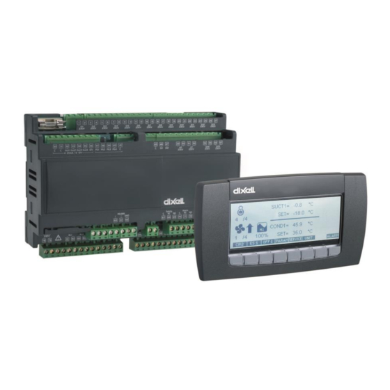
- Page 1 XC1008D-XC1011D- XC1015D and VGC810 (rel. 1.5A)
- Page 2 INDEX GENERAL WARNING LEASE READ BEFORE USING THIS MANUAL AFETY RECAUTIONS WIRING CONNECTIONS XC1008D XC1011D XC1015D ESCRIPTIONS OF THE WIRING CONNECTIONS USER INTERFACE HAT IS DISPLAYED WHEN THE KEYBOARD IS CONNECTED ISPLAY VISUALIZATION ROGRAMMING SERVICE MENU OW TO ENTER THE...
-
Page 3: Electrical Connections
– 1 ANS MANAGEMENT WITH INVERTER FANS GROUP WITH INVERTER MODE OTHERS OFF MODE – ANAGEMENT OF ALL FANS WITH INVERTER PROPORTIONAL INVERTER ALARM LIST 10.1 – LARM CONDITIONS SUMMARY TABLE CONFIGURATION ERRORS MOUNTING & INSTALLATION 12.1 XC1000D DIMENSIONS 12.2 VG810 DIMENSIONS AND MOUNTING ELECTRICAL CONNECTIONS... -
Page 4: Safety Precautions
1. GENERAL WARNING Please read before using this manual This manual is part of the product and should be kept near the instrument for easy and quick reference. The instrument shall not be used for purposes different from those described hereunder. It cannot be used as a safety device. - Page 5 2. Wiring connections 2.1 XC1008D NOTE: according to the models the digital inputs: (3-18) and (52-55) can operates at 230V/120V or 24V. Verify on the controller which is the right voltage that can be applied. ATTENTION Configurable digital inputs (term. 36-43) are free voltage.
- Page 6 2.2 XC1011D NOTE: according to the models the digital inputs: (3-24) and (52-59) can operates at 230V/120V or 24V. Verify on the controller which is the right voltage that can be applied. ATTENTION Configurable digital inputs (term. 36-43) are free voltage. 1592021021 XC1008-1011-1015D GB A5 r.1.5A 12.10.2009 XC1008-1011-1015D 6/66...
- Page 7 2.3 XC1015D NOTE: according to the models the digital inputs: (3-26) and (46-59) can operates at 230V/120V or 24V. Verify on the controller which is the right voltage that can be applied. ATTENTION Configurable digital inputs (term. 36-43) are free voltage. 2.4 Descriptions of the wiring connections 1 - 2 Power supply: WARNING: THE SUPPLY IS 24Vac/dc 3 –26 Digital inputs for safeties of compressors and fans –...
- Page 8 31-32 Analog output 3 (0-10V or 4-20mA depends on the parameter 3Q1) 34-35 Analog output 1 (0-10V or 4-20mA depends on the parameter 1Q1) 33-34 Analog output 2 (0-10V or 4-20mA depends on the parameter 1Q1) 36-37 Configurable digital input 1 (free voltage) 38-39 Configurable digital input 2 (free voltage) 40-41 Configurable digital input 3 (free voltage) 42-43Configurable digital input 4 (free voltage)
- Page 9 88 - 103 and 106 - 119 Relay configurable outputs for compressors, fans, alarms and aux. The functioning of the relays depends on the setting of the correspondent C(i). 3. User interface 3.1 What is displayed when the keyboard is connected Where: release: Rel Firmware XC1000D / release OS Visograph / release Program Visograph Push the ENTER key to enter the standard visualization...
- Page 10 3.2 Display visualization Symbol of compressor: it’s present for the following configuration of the parameter C0. C0 = 1A0D; 1A1D, 2A0D, 2A1D, “2A2D Status of the suction section: The pressure (temperature) is below the regulation band and the capacity of the plant is decreasing The pressure (temperature) is above the regulation band and the capacity of the plant is increasing...
- Page 11 (10) Analog output status for inverter for fan: it’s present only if an inverter for fan is used. It displays the percentage of the analog output driving the inverter. Not present if the “free” analog output is used. (11) Status of the delivery section: The condenser pressure (temperature) is below the regulation band and the number of fans is decreasing The condenser pressure (temperature) is above the regulation band and the number...
- Page 12 3.3 Programming Push the key and the programming menu is entered. Parameters are collected in two menu: Pr1: menu of parameters without password. Press the Pr1 key to enter. Pr2: menu of parameters with password. If the password is enabled, use the following procedure to put it.
-
Page 13: Table Of Contents
Push the ENTER key to enter in Pr2 menu 3.3.2 Parameters grouping The parameters are collected in sub-menu according to the following interface. The parameters sub menu are the following: Set Point (SETC1-SETF2) Compressor Rack setup (C0-C18, C34-C36) Regulation (C37-C44) Display (C45-C46) Analog Inputs of regulation (Ai1-Ai15) Analog Inputs of auxiliary (Ai16-Ai28) - Page 14 Fan Alarms (AF1-AF17) Dynamic Setpoint Suction (o1-o8) Condenser Set point (O9-O14) Analog outputs configuration (1Q1, 3Q1) Analog Outputs 1 (1Q1-1Q26) Analog Outputs 2 (2Q1-2Q25) Analog outputs 3 (3Q2-3Q26) Analog outputs 4 (4Q1-4Q25) Auxiliary Outputs (AR1-AR12) Other (oT1-OT9) NOTE: some sub menu could be absent depending on the model. Push the SET key to enter a menu and the parameter with their value will be displayed: see below picture.
- Page 15 4. SERVICE MENU The service menu collect the main functions of the controller. From the Service menu is possible to: see the values of analog outputs see the status of compressor relay operate a maintenance section see the status of safety and configurable digital inputs see the values of the probes set the real time clock use the HOT KEY to program the instrument or to program the HOT KEY...
- Page 16 4.2 How to program an instrument using a HOT KEY The XC1000D uses a standard Dixell HOT KEY (cod. DK00000100). 4.2.1 How to program the HOT KEY. Program one controller with the front keypad. When the controller is ON, insert the “Hot key”. Enter the SERVICE menu and push the UPL key.
- Page 17 This outputs can be used to drive an external inverter or to repeat a main probe, by means of a signal 4-20mA or 0-10V. 4.4 How to see the status of the relays Procedure: Enter the SERVICE menu Select LOADS STATUS Push the SET key.
- Page 18 4.5.2 How to disabled/enabled an output during a maintenance section. To disabled an output during a maintenance session means to exclude the output from the regulation: To do it act as in the following Enter the COMPRESSOR SERVICE sub-menu, as described in the previous paragraph. Select the load by means of the UP and DOWN keys.
- Page 19 4.5.5 How to erase the running hours of a load After a maintenance session usually is useful to erase the running our of a load. To do it act as in the following Enter the COMPRESSOR SERVICE sub-menu, as described in the paragraph. 4.5.1. Select the load by means of the UP and DOWN keys.
- Page 20 HP, LP and configurable inputs 4.7 How to see the values of the probes Procedure: Enter the SERVICE menu Select PROBES sub-menu Push the SET key. The PROBES sub-menu displays the probe values, with the following layout: To change the measurement unit for the probe PB1, PB2, PB3, PB4, push UNIT button. 4.8 How to set time and date Procedure: Enter the SERVICE menu...
- Page 21 Set the day by means of the UP and DOWN keys. Push the SET key, to confirm and pass to the setting of time. Use the same procedure for the date. Then confirm the selection by means of the SET key. NOTE: to memorise the alarms and to enable the automatic energy saving cycle the real time clock has to be set.
- Page 22 Premere il tasto ENTER per entrare nel menu allarmi The alarm menu displays the active alarm with the following layout: (1) = alarm code (2) = alarm description Push the LOG button to enter the ALARM ACTIVE log, as shown in the following picture 5.2 Active alarm log menu This menu contains all the information concerning the active alarms.
-
Page 23: Compressor Rack Setup (C0-C18, C34-C)
5.3 Active alarm log menu Push the LOG button to enter the ALARM LOG. This menu contains all the memorised alarms. For each alarm the starting time and date and the finish time and date are recorded. Push the ERASE button to delete the whole archive of alarms. The following display is shown: Push the CONFIRM button to confirm the operation and delete the archive. - Page 24 Kind of plant Only condenser fan 0A1d Delivery 1 Only compressors 1A0d Suction 1 Compressors and 1A1d Suction 1 Delivery 1 fans 1 circuit Fans of circuit 1 0A2d Delivery 1 Delivery 2 and 2 2A0d Compressors of Suction 1 Suction 2 circuit 1 and 2 2A1d...
- Page 25 C8 = FAn1; C9 = FAn1; C10 = FAn1; C11 = FAn1; C12 = nu C13 = nu C14 = nu C15 = nu PLANT CONFIGURATION EXAMPLE: Plant with 1 circuit with 6 compressors e 5 fans: C0 = 1A1d; C1 = CPr1;...
-
Page 26: Regulation (C37-C)
C1 = Frq1; C2 = CPr1; C3 = CPr1, C4 = Stp, C5 = Fan1; C6 = FAn1; C7 = FAn1; C8 = Frq2; C9 = Cpr2; C10 = Cpr2; C11 = Frq2F; C12 = Fan2; C13 = Fan2; C14 = nu C15 = nu Kind of compressors: to set the kind of compressors. - Page 27 CINT: °C with decimal point (bar); F: °F (PSI); BAR: bar (°C); PSI: PSI (°F); KPA: KPA (°C) CKPA: °C (KPA) NOTE1: changing the measurement unit, the instrument will update parameter values that refer to pressure or temperature. NOTE2: parameters with probe calibration, are reset during the measurement unit change. Pressure display: it indicates if the range of the probes are related to relative or absolute pressure.
- Page 28 nu = not used Au1 = thermostat probe for AUX1 relay; Au2 = thermostat probe for AUX2 relay; Au3 = thermostat probe for AUX3 relay; Au4 = thermostat probe for AUX4 relay; otC1 = for the optimization of the delivery pressure/temperature, circuit 1 (dynamic set of delivery circuit 1);...
-
Page 29: Safety Digital Inputs (Di2-Di)
otA2 = for the optimization of the suction pressure/temperature, (dynamic set point) circuit 2 (dynamic set of suction circuit 2) AI27 Probe 4 AUX calibration: -12.0 ÷ 12.0 °C; -120 ÷ 120 °F AI28 Alarm relay on with auxiliary probe fault: nu = relay not present;... - Page 30 noCRO = it disables the set point coming from the supervising system, and it restores SETC1 and SETC2 set. noSTD1 = it disables the dynamic set point on the circuit 1, and it restores SETC1 and SETF1 set. noSTD2 = it disables the dynamic set point on the circuit 2, and it restores SETC2 and SETF2 set. DI16 Delay of configurable d.i.
-
Page 31: Compressor Action (Cp1-Cp)
6.1.8 Compressor Action (CP1-CP8) Regulation band width for compressors- circuit 1 (0.10÷10.00 bar; 0.1÷25.0°C, 1÷80PSI, 1÷50°F; 10÷1000 KPA) The band is symmetrical compared to the target set point, with extremes: SETC1+(CP1)/2 ... SETC1-(CP1)/2. The measurement unit depends on the C45 par. NOTE: If the circuit 1 has 1 relay set as a frequency compressor (Frq1), the 1Q19 parameter is used instead of the CP1 parameter: regulation band width that is added to the set point 1. -
Page 32: Fan Action (F1-F)
6.1.10 Fan Action (F1-F8) Regulation band width for fans – circuit 1 (0.10÷10.00 bar; 0.1÷30.0°C, 1÷80PSI, 1÷50°F; 10÷1000 KPA) Set the C45 par. and the target set point for fans before setting this parameter. The band is symmetrical compared to the fan target set point, with extremes: SETF1-(F1)/2 ... SETF1+(F1)/2. - Page 33 Low pressure (temperature) alarm for compressors – circuit 1: (0.10 ÷ 30.00bar; 0.0 ÷ 100.0°C; 1÷430 PSI; 1÷200.0°F; 10 ÷ 3000KPA) The measurement unit depends on C45 parameter. AC3 is always subtracted to the set point SETC1. When the value SETC1-AC3 is reached the “Low alarm - Suction 1” is enabled, (possibly after the AC5 delay time) High pressure (temperature) alarm for compressors –...
- Page 34 The measurement unit depends on C45 parameter. AF2 is always added to the set point SETF1. When the value SETF1+AF2 is reached the “High alarm – Condenser 1” is enabled, (possibly after the AF3 delay time) Low and High fan pressure (temperature) alarms delay – circuit 1 (0÷255 min) time interval between the detection of a pressure (temperature) alarm condition and alarm signalling.
- Page 35 with AUX temper. < O3 ==> “Real SEtC1” = O2 with AUX temper. > O4 ==> “Real SEtC1” = SEtC1 with O3 < AUX temper < O4 ==> SEtC1 < “Real SEtC1” < O2 Suction 1 Set point SEtC1 Temperature Dynamic compressor set point function enabled - circuit 2 no = standard regulation yES = the SETC2 varies according to the setting of O6, O7, O8.
- Page 36 Example With the external temperature (otc1) > SETF1-O11 ==> “real SEtF1” = SETF1 With the external temperature (otc1) < O10-O11 ==> “real SetF1”= O10 With O10-O11 < external temperature (otc1) < SETF1-O11 ==> O10 <“real SEtF1”< SEtF1 where external temperature (otc1) is the temperature detected by the auxiliary probe set as otC1 Fan 1 Set point SEtF1...
- Page 37 Pbc1= Suction Probe, circuit 1 (term. 62-63 or 62 -68) Pbc2 = Suction Probe, circuit 2 (term. 64-63 or 64 -68) Adjustment of read out for the analog output 1 (-1.00÷100.00 bar; -15÷750PSI; -50÷150°C; - 58÷302°F; -100÷10000 KPA). It’s used only when 1Q2 = FREE Adjustment of read out for the analog output 1 at 20mA/10V (-1.00÷100.00 bar;...
- Page 38 FAN2 = output for inverter fans – circuit 2 (only some fans driven by inverter, others enabled by on/off); INVF1 = not used INVF2 = not used nu = not used Reference probe for analogue output 2, it’s used only when 2Q1 = FREE Pbc1= Suction Probe, circuit 1 (term.
- Page 39 6.1.20 Analog Output 3 (3Q2-3Q26) Analog output 3 function (term. 31-32) FREE = pure analogue output CPR = output for inverter frequency compressor – circuit 1 CPR2 = output for inverter frequency compressor – circuit 2 FAN = output for inverter fans – circuit 1 (only some fans driven by inverter, others enabled by on/off); FAN2 = output for inverter fans –...
- Page 40 3Q24 Minimum inverter capacity with poor lubrication (0÷99%; with 0 function excluded) If the frequency compressor works for the 3Q25 time with a frequency (in percentage) equal or lower than 3Q24, it is forsed to work at 100% for the 3Q26 time in order to make the right lubrication. 3Q25 Time of lower inverter time (1÷255min) 3Q26...
- Page 41 4Q20 Band offset (-12.0÷12.0°C -12.00 ÷ 12.00BAR, -120÷120°F, -120÷120PSI; -1200÷1200KPA). Used to move the regulation band across to the set point. 4Q21 Integral action limitation (0.0÷99.0 °C; 0÷180°F; 0.00÷50,00bar; 0÷725PSI; 0÷5000kPA) to stop the increasing of integral action when the pressure reaches the SET + 1Q22 value. 4Q23 Minimum inverter capacity with poor lubrication (0÷99%;...
- Page 42 OP = alarm conditions 84-85 closed CL = alarm conditions 84-85 open Alarm relay 1 off by keyboard It’s referred to the relays configured as ALr1 no = alarm relay remains on for all the duration of the alarm yES = the alarm relay is switched off by pushing a key Alarm relay 1 polarity OP = the alarm relay terminals are open during an alarm CL = the alarm relay terminals are closed during an alarm...
- Page 43 7.2 Proportional band adjustment – for compressors and fans This kind of regulation is available for compressors and fans. It is used by compressors if the parameter C37 = Pb (C38 = Pb for circuit 2). The following observations are availables only for adjustment without inverter.
- Page 44 1592021021 XC1008-1011-1015D GB A5 r.1.5A 12.10.2009 XC1008-1011-1015D 44/66...
- Page 45 8. SCREW COMPRESSORS Loads activation is managed by the neutral zone. They follows general rules of step compressors: a. C1..C14 = screw1 or screw2 have to be present, following C2..C15 that are set as Stp, are linked to C1..C14 = screw The relay group is activated depending on the kind of screw compressors that has been selected on the C16 parameter.
- Page 46 ES. Compressor with 4 steps: C1 = Scrw1; C2 = Stp; C3 = Stp; C4 = Stp; C16 = Frtz a. Activation with valves ON due to voltage presence. (C17=cL) C1 = Screw1 C2 = stp C3 = stp C4 = stp C1 = Screw1 C1 = Screw1 C1 = Screw1...
- Page 47 9. ANALOG OUTPUTS FOR INVERTER 9.1 Compressor management The analog outputs can be used in a rack with frequency compressor, driven by an inverter. The regulation of the compressors in this case is changed as described in the following graph: The following examples shows the behaviour of the analog output with proportional regulation.
- Page 48 3 compressors, 1 frequency compressor, C1 = FRQ1 C37 = db 1Q8 = 100 C2 = CPR1 1Q2 = CPR C3 = CPR1 1Q7 = 100 where Minimum value for analog out.1 0 ÷ 100 % 0 ÷ 255 (sec) 1Q12 Regulation delay after entering the regulation band 0 ÷...
- Page 49 9.2 Fans management with inverter– 1 fans group with inverter mode, others ON in on/off mode With this configuration, one analog output can be used to drive the inverter (1Q2 or 2Q1 or 3Q2 or 4Q1 = FAN or FAN2). Set the first fans relay as inverter (FRQ1F or FRQ2F), and other relays as fans (FAN1 or FAN2).
- Page 50 Below the SETF the output is OFF, above the SETF the output works at 100%. If the delivery pressure/temperature is higher than the SETF1(2) value, the relay set as inverter is ON; if the delivery pressure is lower than the SETF1(2) value the relay is OFF. 9.3.1 Use of fans thermal protection With this configuration it’s possible to use XC1000D digital inputs to monitor the fans functioning.
- Page 51 10.1 Alarm conditions – summary table Code Description Cause Action Reset E0L1 Low pressure- Low pressure All compressors Automatically if the number of activation are less (E0L2) switch alarm switch input 1 (2) than Ac12 (Ac16) in the Ac13 (Ac17) time when of circuit 1 (2) are for circuit 1 (2) enabled,...
- Page 52 Code Description Cause Action Reset LAC1 Minimum Suction pressure Automatically: as soon as the pressure or signalling only (LAC) pressure or temperature temperature reaches the SETC1-AC3 (SETC2 – (temperature) lower than AC6) + differential value. alarm SETC1-AC3 (differential = 0.3bar or 1°C) compressors (SETC2 –AC6) for circuit 1...
- Page 53 11. Configuration errors Error N. Parameters Alarm description Action C1-C15 different from Screw1 or Compressors configuration alarm. Machine stop (all relays Screw2 Set properly par. C16 configured as compr. or C16 = Btz or Frsc fans OFF) One of C1-C15 parameters= Compressors configuration alarm.
- Page 54 12.1 XC1000D dimensions 1592021021 XC1008-1011-1015D GB A5 r.1.5A 12.10.2009 XC1008-1011-1015D 54/66...
- Page 55 12.2 VG810 dimensions and mounting 1592021021 XC1008-1011-1015D GB A5 r.1.5A 12.10.2009 XC1008-1011-1015D 55/66...
- Page 56 13. Electrical connections The instruments are provided with disconnectable screw terminal blocks to connect cables with a cross section up to 2,5 mm Before connecting cables make sure the power supply complies with the instrument’s requirements. Separate the input connection cables from the power supply cables, from the outputs and the power connections.
- Page 57 XC1008D: 8 (relè 7A 250Vac) Analog inputs: XC1011D, XC1015D: 4 x 4-20mA o 0÷5V o NTC configurable probe. XC1008D: 2 x 4-20mA o 0÷5V o NTC configurable probe. Safety alarm inputs – main voltage: XC1008D: 8, main voltage, connected to the loads...
- Page 58 16. Default setting Nome Level Description Range 1008 1011 1015 -18.0 -18,0 -18,0 Compressor set point circuit 1 SETC1 35.0 35,0 35,0 Fan set point circuit 1 SETF1 SETC2 -18.0 -18,0 -18,0 Compressor set point circuit 2 35.0 35,0 35,0 Fan set point circuit 2 SETF2 1A1d...
- Page 59 Nome Level Description Range 1008 1011 1015 Kind of gas 0 ÷ 255 Screw compressors' second step 0 ÷ 255 activation delay Screw compressors' first step used in 0 ÷ 255 regulation Regulation for compressor circuit 1 0 ÷ 255 Regulation for compressor circuit 2 0 ÷...
- Page 60 Nome Level Description Range 1008 1011 1015 Probe 7 action type nu = not used ; AI23 Au1 = Probe for AUX1 thermostat; Au2 = Probe for AUX2 thermostat; Au3 = Probe for AUX3 thermostat; Au4 = Probe for AUX4 thermostat; otC1 = dynamic set point for delivery –...
- Page 61 Nome Level Description Range 1008 1011 1015 -40,0 -40.0 -40.0 Minimum set point circuit 1 BAR: (AI2 ÷ SETC1); °C: (-50.0 ÷ SETC1); PSI : (AI2 ÷ SETC1); °F : (-58.0 ÷ SETC1) 10,0 10.0 10.0 Maximum set point circuit 1 BAR: (SETC1÷AI3);...
- Page 62 Nome Level Description Range 1008 1011 1015 Energy Saving start time on Sunday 0:0÷23.5h; nu HS13 00,00 00:00 00:00 Sunday Energy Saving duration 0:0÷23.5h; HS14 Probe 1 alarm delay at power on 0 ÷ 255 (min) Probe 2 alarm delay at power on 0 ÷...
- Page 63 Nome Level Description Range 1008 1011 1015 300÷300 (°F) -90÷90 Dynamic set enabled - circuit 2 no - YES 25.0 25.0 Minimum condens. set - circuit 2 F6÷SETF2 15.0 15.0 Differential dynamic set-circuit 2 (BAR) -20.00÷20.00 (°C) -50.0÷50.0 (PSI) - 300÷300 (°F) -90÷90 4.20mA 4.20mA 4.20mA Analog outputs 1-2 setting...
- Page 64 Nome Level Description Range 1008 1011 1015 Safety value for Analog output 2 0 ÷ 100 (%) 2Q10 Regulation delay after exit from neutral 0 ÷ 255 (sec) 2Q11 zone Analog output 2 rise time 0 ÷ 255 (sec) 2Q12 Analog output 2 permanency before 0 ÷...
- Page 65 Nome Level Description Range 1008 1011 1015 Maximum time at minimum capacity of 1÷255min 3Q25 inverter 3 3Q26 Time at maximum capacity of inverter 3 1÷255min Analog output 4 function FREE – CPR - CPR2 - FAN - FAN2 - INVF1 - INVF2 - nu Pbc4 Pbc4...
- Page 66 Nome Level Description Range 1008 1011 1015 Off function enabling no - YES 1592021021 XC1008-1011-1015D GB A5 r.1.5A 12.10.2009 XC1008-1011-1015D 66/66...