Table of Contents
Advertisement
Instruction
Manual
To learn more about Porter-Cable
visit our website at:
http://www.porter-cable.com
Copyright © 2004 PORTER-CABLE Corporation
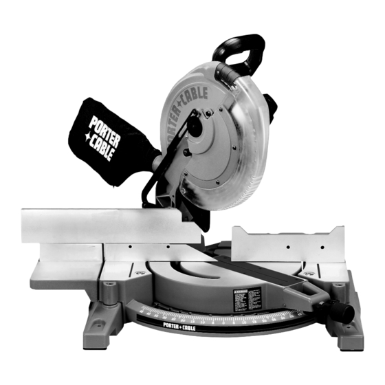
12" Compound Laser Miter Saw
Please make certain that the person who is to use
this equipment carefully reads and understands
these instructions before starting operations.
The Model and Serial No. plate is located on the main
housing of the tool. Record these numbers in the
spaces below and retain for future reference.
Model No. _____________________________________
Type __________________________________________
Serial No.______________________________________
ESPAÑOL: PÁGINA 23
FRANÇAISE : PAGE 43
MODEL 3802L
IMPORTANT
Part No. 906984 - 07-20-04
Advertisement
Table of Contents

Related Manuals for Porter-Cable 3802L


Summary of Contents for Porter-Cable 3802L
- Page 1 Instruction Manual To learn more about Porter-Cable visit our website at: http://www.porter-cable.com Copyright © 2004 PORTER-CABLE Corporation ESPAÑOL: PÁGINA 23 FRANÇAISE : PAGE 43 12" Compound Laser Miter Saw MODEL 3802L Please make certain that the person who is to use this equipment carefully reads and understands these instructions before starting operations.
-
Page 2: Table Of Contents
NOT be modified and/or used for any application other than for which it was designed. If you have any questions relative to its application DO NOT use the product until you have written Porter Cable and we have advised you. Online contact form at http://www.porter-cable.com Postal Mail: Technical Service Manager Porter Cable... -
Page 3: Safety Guidelines
SAFETY GUIDELINES - DEFINITIONS It is important for you to read and understand this manual. The information it contains relates to protecting YOUR SAFETY and PREVENTING PROBLEMS. The symbols below are used to help you recognize this information. Indicates an imminently hazardous situation which, if not avoided, will result in death or serious injury. Indicates a potentially hazardous situation which, if not avoided, could result in death or serious injury. -
Page 4: General Safety Rules
Porter-Cable may cause hazards or risk of injury to persons. REDUCE THE RISK OF UNINTENTIONAL STARTING. Make sure switch is in “OFF” position before plugging in power cord. -
Page 5: Additional Specific Safety Rules
15. NEVER START THE TOOL with the workpiece against the blade. 16. KEEP HANDS out of path of saw blade. Clamp all workpieces that would require your hand to be in the “Table Hazard Zone” (within the red lines). -
Page 6: Functional Description
MOTOR Many Porter-Cable tools will operate on either D.C., or single phase 25 to 60 cycle A.C. current and voltage within plus or minus 5 percent of that shown on the specification plate of the tool. Several models, however, are designed for A.C. -
Page 7: Carton Contents
7/16"Open end wrench (supplied) ASSEMBLY TIME ESTIMATE Assembly time for this unit is approximately 30 minutes. CARTON CONTENTS Fig. 2 Fig. 3 Miter Saw Extension table Fence slide Fence slide support Dust bag 1/2" Arbor and fence wrench 1/4" hex wrench Open end 7/16"... -
Page 8: Moving Cuttinghead To The Up Position
“ADJUSTING SLIDING FIT BETWEEN MOVABLE TABLE AND BASE.” ATTACHING EXTENSION TABLE AND FENCE SLIDE Attach flat washers to the two 5/16-18 x 3/4” screws (A) Fig. 8. Thread the screws into the holes on left side of the saw (Figs. 8 & 9). - Page 9 Use a straight edge (C) Fig. 12 to align the fence slide support (E) with the saw fence (J), and tighten the two screws. Position the fence slide (K) Fig. 13 on top of the saw fence (J) and the fence slide support (E). Move the fence slide (K) back and forth several times to check the alignment of the fence slide support (E).
-
Page 10: Operation
To start the machine, depress the switch trigger (A) Fig. 19. To stop the machine, release the switch trigger. This saw is equipped with an automatic electric blade brake. As soon as the switch trigger (A) Fig. 19 is released, the electric brake is activated and stops the blade in seconds. -
Page 11: Adjusting Sliding Fit Between Movable Table And Base
(opposite to decrease the fit). This adjustment should not be so tight that it restricts the rotating movement of the table, or so loose that it affects the accuracy of the saw. ADJUSTING FENCE 90° TO BLADE IMPORTANT: Before making this adjustment, set the blade at 0° to the table. See section “ADJUSTING 0° AND 45° BEVEL POSITIVE STOPS.”... -
Page 12: Tilting Cuttinghead For Bevel Cutting
The sliding fence (Fig. 29) provides support for extra large workpieces used with your saw and should always be set as close as possible to the saw blade. When miter cutting (blade 90° to the table and at an angle to the right or left), set the fence all the way toward the blade (Fig. -
Page 13: Adjusting Chip Deflector
ADJUSTING 0° AND 45° BEVEL POSITIVE STOPS DISCONNECT THE MACHINE FROM THE POWER SOURCE. Adjust the saw so that both the bevel and miter pointers are set at 0°. Tighten the bevel lock handle and lock the cuttinghead in the down position. -
Page 14: Adjusting Sliding Fit Between Trunnion And Bevel Bracket
To adjust, tighten the nut (D). This adjustment should not be so tight that it restricts the sliding movement of the cuttinghead arm (B) or so loose that it affects the accuracy of the saw cut. ADJUSTING DOWNWARD TRAVEL OF SAW BLADE DISCONNECT THE MACHINE FROM THE POWER SOURCE. - Page 15 HOW TO CHECK LASER ALIGNMENT Make sure the saw is set to 0 degrees, miter and bevel, and clamp a 2"x 6" board on the saw. Create a partial test cut in the workpiece (Fig. C). Turn the laser “ON/OFF” switch (Fig. B) to the “ON” position. Leave the workpiece clamped in place for the remainder of the adjustment.
- Page 16 (Fig. A). Use the 1/8" hex wrench to turn the left or right vertical alignment set screws. If, as the saw head goes from a raised to a lowered position, the laser line moves horizontally away from the blade, turn the vertical alignment set screw clockwise to correct.
-
Page 17: Typical Operations And Helpful Hints
Aluminum extrusions (aluminum screens and storm windows) can easily be cut with your miter saw. When cutting aluminum extrusions, or other sections that can be cut with a saw blade and are within the capacity of the machine, position the material so that the blade is cutting through the smallest cross-section (Fig. -
Page 18: Cutting Bowed Material
2. If the material is positioned the wrong way (Fig. 44), the workpiece will pinch the blade near the completion of the cut. CORRECT One of the many features of the saw is the ease of cutting crown moulding. The following is an example of cutting both inside and outside corners on 52°/38° wall angle crown moulding. -
Page 19: Troubleshooting
2 x 4’s (C) can used. If these are too high, cut the 2 x 4s (C) to provide this height or use other properly-sized wood For assistance with your tool, visit our website at www.porter-cable.com for a list of service centers or call the Porter-Cable help line at 1-800-487-8665. TROUBLESHOOTING... -
Page 20: Maintenance
Remove the arbor screw (E) Fig. 51 by turning the screw clockwise with the supplied wrench, while at the same time, pressing in on the arbor lock (F) Fig. 52. Remove the outside blade flange (G) Fig. 51, and saw blade. Do not remove the inside blade flange. -
Page 21: Service
(model number, type, serial number, etc.). A complete line of accessories is available from your Porter-Cable Porter-Cable Authorized Service Stations. Please visit our Web Site www.porter-cable.com for a catalog or for the name of your nearest supplier. -
Page 22: Warranty
ONE YEAR WARRANTY Porter-Cable warrants its Professional Power Tools for a period of one year from the date of original purchase. We will repair or replace at our option, any part or parts of the product and accessories covered under this warranty which, after examination, proves to be defective in workmanship or material during the warranty period. -
Page 23: Español
Phone: (604) 420-0102 Fax: (604) 420-3522 The following are trademarks of PORTER-CABLE • DELTA (Las siguientes son marcas registradas de PORTER-CABLE • DELTA S.A.) (Les marques suivantes sont des marques de fabriquant de la PORTER-CABLE • DELTA): Auto-Set Contractor’s Saw II™, Delta ®...