Table of Contents
Advertisement
Instruction
Manual
To learn more about Porter-Cable
visit our website at:
http://www.porter-cable.com
Copyright © 2004 PORTER-CABLE Corporation
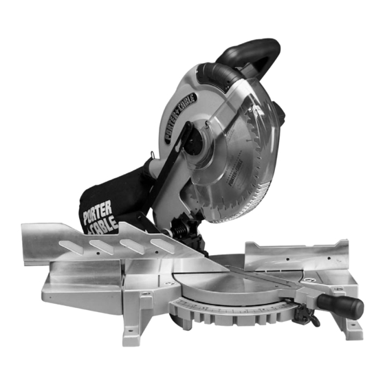
10" Compound Laser Miter Saw
Please make certain that the person who is to use
this equipment carefully reads and understands
these instructions before starting operations.
The Model and Serial No. plate is located on the main
housing of the tool. Record these numbers in the
spaces below and retain for future reference.
Model No. _____________________________________
Type __________________________________________
Serial No.______________________________________
ESPAÑOL: PÁGINA 23
FRANÇAISE : PAGE 45
MODEL 3700L
IMPORTANT
Part No. A05636 - 08-06-04
Advertisement
Table of Contents

Related Manuals for Porter-Cable 3700L


Summary of Contents for Porter-Cable 3700L
- Page 1 Instruction Manual To learn more about Porter-Cable visit our website at: http://www.porter-cable.com Copyright © 2004 PORTER-CABLE Corporation ESPAÑOL: PÁGINA 23 FRANÇAISE : PAGE 45 10" Compound Laser Miter Saw Please make certain that the person who is to use this equipment carefully reads and understands these instructions before starting operations.
-
Page 2: Table Of Contents
NOT be modified and/or used for any application other than for which it was designed. If you have any questions relative to its application DO NOT use the product until you have written Porter Cable and we have advised you. Online contact form at http://www.porter-cable.com Postal Mail: Technical Service Manager Porter Cable... - Page 3 SAFETY GUIDELINES - DEFINITIONS It is important for you to read and understand this manual. The information it contains relates to protecting YOUR SAFETY and PREVENTING PROBLEMS. The symbols below are used to help you recognize this information. Indicates an imminently hazardous situation which, if not avoided, will result in death or serious injury. Indicates a potentially hazardous situation which, if not avoided, could result in death or serious injury.
-
Page 4: Important Safety Instructions
Porter-Cable may cause hazards or risk of injury to persons. REDUCE THE RISK OF UNINTENTIONAL STARTING. Make sure switch is in “OFF” position before plugging in power cord. -
Page 5: Additional Safety Rules For Miter Saws
15. NEVER START THE TOOL with the workpiece against the blade. 16. KEEP HANDS out of path of saw blade. Clamp all workpieces that would require your hand to be in the “Table Hazard Zone” (within the red lines). -
Page 6: Power Connections
POWER CONNECTIONS A separate electrical circuit should be used for your machines. This circuit should not be less than #12 wire and should be protected with a 20 Amp time lag fuse. If an extension cord is used, use only 3-wire extension cords which have 3- prong grounding type plugs and matching receptacle which will accept the machine’s plug. -
Page 7: Functional Description
FUNCTIONAL DESCRIPTION FOREWORD Porter-Cable Model 3700L is a high capacity, 10" compound laser miter saw designed to cut wood and non-ferrous metals. This unit incorporates the latest technology TwinLaser™ line-of-cut indicator feature. It can crosscut 5-1/2" x 2-3/8" and 3-1/2" x 3-1/16", miter at 45° right 3-3/8" x 3-1/16", miter at 45° left 2-5/8" x 3-7/16", bevel at 45° left 5-1/2"... -
Page 8: Assembly
UNPACKING AND CLEANING 1. Carefully remove the machine from the carton. Retain all packing materials until you have inspected and satisfactorily operated the machine. Do not operate this machine until you read and understand the entire instruction manual. 2. Place the machine on a firm, level surface with extra room for handling and proper support of the workpiece. 3. - Page 9 Use a straight edge to align the fence slide support with the saw fence, and tighten the two screws. Position the fence slide (K) Fig. 8 in the valley on the top of the saw fence (J) and the fence slide support (E). Move the fence slide (K) back and forth several times to check the alignment of the fence slide support (E).
-
Page 10: Operation
To start the machine, depress the switch trigger (A) Fig. 13. To stop the machine, release the switch trigger. This saw is equipped with an automatic electric blade brake. As soon as the switch trigger (A) Fig. 13 is released, the electric brake is activated and stops the blade in seconds. - Page 11 ROTATING THE TABLE FOR MITER CUTTING This miter saw will cut any angle from 0° to 47° right and left. Turn the locking knob (A) Fig. 15 counter-clockwise, lift the miter detent trigger (B), and rotate the table. The compound miter saw is equipped with positive stops at 0°, 15°, 22.5°, 30°, and 45° left and right.
-
Page 12: Tilting Cuttinghead For Bevel Cutting
The sliding fence (A) Fig. 23 provides support for extra large workpieces used with your saw. Set it as close as possible to the saw blade. When miter cutting (blade 90° to the table and at an angle to the right or left), set the fence all the way toward the blade (Fig. -
Page 13: Adjusting Sliding Fit Between Cuttinghead Arm And Trunnion
ADJUSTING 0° AND 45° BEVEL POSITIVE STOPS DISCONNECT THE MACHINE FROM THE POWER SOURCE. Adjust the saw so that both the bevel and miter pointers are set at 0°. Tighten the bevel lock handle (A) Fig. 25 and lock the cuttinghead in the down position. -
Page 14: Adjusting Downward Travel Of Saw Blade
HOW TO CHECK LASER ALIGNMENT Make sure the saw is set to 0 degrees, miter and bevel, and clamp a 2"x 6" board on the saw. Create a partial test cut in the workpiece (Fig. C). Turn the laser “ON/OFF” switch (Fig. B) to the “ON” position. Leave the workpiece clamped in place for the remainder of the adjustment. - Page 15 (Fig. A). Use the 1/8" hex wrench to turn the left or right vertical alignment set screws. If, as the saw head goes from a raised to a lowered position, the laser line moves horizontally away from the blade, turn the vertical alignment set screw clockwise to correct.
-
Page 16: Typical Operations And Helpful Hints
Remove the blade from the saw and clean pitch build-up from the blade (Fig. K) Pitch build-up can block the laser and prevent it from accurately indicating the line-of-cut. -
Page 17: Auxiliary Wood Fence
Fig. 34. This auxiliary fence is constructed of straight wood approximately 1/2" thick by 3" high by 20" long. NOTE: The auxiliary fence (A) is used ONLY with the saw blade in the 0 degree bevel position (90 degrees to the table). When bevel cutting (blade tilted), remove the auxiliary fence. -
Page 18: Cutting Aluminum
NOTE: Ensure that the top of the support 2 x 4’s (C) are level with the miter saw table. This is critical because the distance from the top of the 2 x 4’s (A) to the miter saw table varies from saw to saw. In most cases, standard 2 x 4’s (C) can used. -
Page 19: Cutting Crown Moulding
CUTTING CROWN MOULDING One of the many features of the saw is the ease of cutting crown moulding. The following is an example of cutting both inside and outside corners on 52°/38° wall angle crown moulding. 1. Move the table to the 31.62° right miter position and lock the table in position. -
Page 20: Troubleshooting
For assistance with your tool, visit our website at www.porter-cable.com for a list of service centers or call the Porter-Cable help line at 1-800-487-8665. CHANGING THE BLADE Use only cross-cutting saw blades. When using carbide-tipped blades, do not use blades with deep gullets as they can deflect and contact the guard. -
Page 21: Service
AUTHORIZED PORTER-CABLE SERVICE STATION or a PORTER-CABLE•DELTA FACTORY SERVICE CENTER. At approximately 100 hours of use, take or send your tool to your nearest authorized Porter-Cable Service Station to be thoroughly cleaned and inspected. Have worn parts replaced and lubricated with fresh lubricant. Have new brushes installed, and test the tool for performance. -
Page 22: Warranty
Porter-Cable warrants its Professional Power Tools for a period of one year from the date of original purchase. We will repair or replace at our option, any part or parts of the product and accessories covered under this warranty which, after examination, proves to be defective in workmanship or material during the warranty period. - Page 23 Phone: (604) 420-0102 Fax: (604) 420-3522 The following are trademarks of PORTER-CABLE • DELTA (Las siguientes son marcas registradas de PORTER-CABLE • DELTA S.A.) (Les marques suivantes sont des marques de fabriquant de la PORTER-CABLE • DELTA): Auto-Set Contractor’s Saw II™, Delta ®...