Table of Contents
Advertisement
Instruction
Manual
To learn more about Porter-Cable
visit our website at:
http://www.porter-cable.com
Copyright © 2000 PORTER-CABLE Corporation
ESPAÑOL: PÁGINA 21
FRANÇAISE : PAGE 41
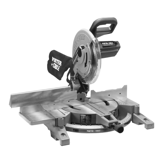
12" Compound
Miter Saw
MODEL 3802
IMPORTANT
Please make certain that the person who is to
use
this
equipment
understands these instructions before starting
operations.
The Model and Serial No. plate is located on the main
housing of the tool. Record these numbers in the
spaces below and retain for future reference.
Model No. _____________________________________
Type __________________________________________
Serial No.______________________________________
carefully
reads
and
Part No. 900988 - 11-30-00
Advertisement
Table of Contents

Related Manuals for Porter-Cable 3802


Summary of Contents for Porter-Cable 3802
- Page 1 Instruction Manual To learn more about Porter-Cable visit our website at: http://www.porter-cable.com Copyright © 2000 PORTER-CABLE Corporation ESPAÑOL: PÁGINA 21 FRANÇAISE : PAGE 41 12" Compound Miter Saw MODEL 3802 IMPORTANT Please make certain that the person who is to...
-
Page 2: Important Safety Instructions
This tool was designed for certain applications.DO NOT modify or use it for any application other than for which it was designed. If you have any questions relative to its application do not use the tool until you have written Porter-Cable and we have advised you. WARNING: FAILURE TO FOLLOW THESE RULES MAY RESULT IN SERIOUS PERSONAL INJURY. -
Page 3: Additional Safety Rules For Compound Miter Saws
Do not allow anyone in this area while saw is in operation. 31. WHEN THE MITER SAW IS NOT IN USE, the switch should be locked in the OFF position to prevent unauthorized use of the saw. -
Page 4: Replacement Parts
FOREWORD Porter-Cable Model 3802 Type 2 is a high capacity 12" compound miter saw designed to cut wood and non- ferrous metals. It can crosscut 8" x 2¼" and 7" x 3¼", miter at 45 both left and right 5¼" x 2¼", bevel at 45 left 6¼"... -
Page 5: Moving Cuttinghead To The Up Position
THE UP POSITION” and “MOVING THE TABLE TO THE 90 DEGREE CUT-OFF POSITION” in this section. 5. Unassembled items are shown in Fig. 3 for identification and use in assembling the saw. 1 Extension table 2 Fence slide 3 Fence slide support... - Page 6 NOTE: Turn the screws only a few threads into the holes at this time. 2. Attach the table extension (B) Figs. 7A and 7B, to left side of saw table, making sure groove of table extension (B) is inside flat washers (C) as shown in Fig. 7B.
- Page 7 Fig. 7C 3. Use a straight edge (C) Fig. 7C, to make the extension table (B) even with saw table (D), and tighten the two screws (A) Fig. 7B. 4. Attach the fence slide support (E) Fig. 7D, to the extension table (B) by using the two 1 1/4” long hex head screws, 5/16”...
- Page 8 When frequently moving the saw from place to place, mount the saw to a 3/4” piece of plywood. The saw can then be easily moved from place to place and the plywood can be clamped to the supporting surface using “C”...
-
Page 9: Locking Switch In The "Off" Position
DANGER: A TURNING SAW BLADE CAN BE DANGEROUS. AFTER COMPLETING CUT, RELEASE SWITCH TRIGGER (A) FIG. 12, TO ACTIVATE BLADE BRAKE. KEEP CUTTINGHEAD DOWN UNTIL BLADE HAS COME TO A COMPLETE STOP. WARNING: THE TORQUE DEVELOPED DURING BRAKING MAY LOOSEN THE ARBOR SCREW. THE ARBOR SCREW SHOULD BE CHECKED PERIODICALLY AND TIGHTENED IF NECESSARY. -
Page 10: Adjusting Fence 90 Degrees To Blade
(opposite to decrease the fit). This adjustment should not be so tight that it restricts the rotating movement of the table, or so loose that it affects the accuracy of the saw. ADJUSTING FENCE 90 DEGREES TO BLADE IMPORTANT: BEFORE MAKING THIS ADJUSTMENT, SET THE BLADE AT 0 DEGREES TO THE TABLE. -
Page 11: Tilting Cuttinghead For Bevel Cutting
Fig. 18 ATTACHING OPTIONAL WORK CLAMP The work clamp is an important accessory. After purchase, the work clamp can be attached to any one of the four holes (A) Fig. 18, provided on the base of the machine, (three of which are shown). 1. -
Page 12: Adjusting Sliding Fence
(A). 2. Positive stops are provided to rapidly position the saw blade at 90 and 45 degrees to the table. Refer to the section of this manual titled “Adjusting 90 and 45 degree bevel positive stops.” The bevel angle of the cutting arm is determined by the position of the pointer (C) Fig. -
Page 13: Adjusting Sliding Fit Between Trunnion And Bevel Bracket
POSITIVE STOPS 1. DISCONNECT THE SAW FROM THE POWER SOURCE. 2. Adjust saw so that both bevel and miter pointers are set at 0 degrees. Tighten bevel lock handle and lock cuttinghead in down position. 3. Place one end of a square (A) Fig. 27 on the table and the other end against the blade. -
Page 14: Adjusting Sliding Fit Between Cuttinghead Arm And Trunnion
This adjustment is made by loosening locknut (A) Fig. 33, and turning adjusting screw (B) in or out until other end of screw (B) contacts stop (C) at the full downward travel of the saw blade. -
Page 15: Typical Operations And Helpful Hints
When cutting aluminum extrusions, or other sections that can be cut with a saw blade and are within the capacity of the machine, position the material so the blade is cutting through the smallest cross-section, as shown in Fig. -
Page 16: Cutting Bowed Material
One of the unique features of the miter saw is the ease of constructing work supports. Fig. 41 illustrates the miter saw mounted to two standard 2 x 4’s (A). Fasten the grooves in the two mounting legs (B), to the 2 x 4’s, using four screws through the four holes in the mounting legs. -
Page 17: Cutting Crown Moulding
Fig. 42 Fig. 43 NOTE: A positive stop is provided to find this angle quickly. The saw blade is already tilted to the 33-7/8 degree bevel position from the previous cut. 5. Place the crown moulding on the table with the WALL EDGE of the crown moulding against the fence and make the cut. -
Page 18: Maintenance
7. Thread arbor screw (E) Fig. 47, into saw arbor by turning screw (E) counterclockwise as far as possible by hand. Then tighten arbor screw (E) with wrench supplied while at the same time pressing in on arbor lock (F) Fig. -
Page 19: Brush Inspection And Replacement
PORTER-CABLE LIMITED ONE YEAR WARRANTY Porter-Cable warrants its Professional Power Tools for a period of one year from the date of original purchase. We will repair or replace, at our option, any part or parts of the product and accessories covered under this warranty which, after examination, proves to be defective in workmanship or material during the warranty period. - Page 20 NOTES...
- Page 21 Porter-Cable products should be obtained by contacting any Porter-Cable Distributor, Authorized Service Center, or Porter-Cable Factory Service Center. If you do not have access to any of these, call 888-848-5175 and you will be directed to the nearest Porter-Cable Factory Service Center. Las Estaciones de Servicio Autorizadas están ubicadas en muchas grandes ciudades.