
Related Manuals for Emerson Rosemount5081


Summary of Contents for Emerson Rosemount5081
- Page 1 Instruction Manual LIQ-MAN-5081, Rev A September 2017 ™ Rosemount 5081 Explosion-Proof Transmitter...
- Page 2 Essential instructions Read this page before proceeding! Emerson designs, manufactures, and tests its Rosemount products to meet many national and international standards. Because these instruments are sophisticated technical products, you must properly install, use, and maintain them to ensure they continue to operate within their normal specifications.
- Page 3 WARRANTIES OF ANY KIND, EXPRESSED OR IMPLIED, AS TO MERCHANTABILITY, FITNESS FOR PARTICULAR PURPOSE, OR ANY OTHER MATTER WITH RESPECT TO ANY OF THE GOODS OR SERVICES. It is understood that corrosion or erosion of materials is not covered by our guarantee. LIMITATION OF REMEDY AND LIABILITY: SELLER SHALL NOT BE LIABLE FOR DAMAGES CAUSED BY DELAY IN PERFORMANCE.
-
Page 5: Table Of Contents
Contents Contents Chapter 1 Startup procedure ......................1 Chapter 2 Description and specifications ..................3 Features and applications .......................3 General specifications ........................3 Hazardous area certifications ......................5 Functional specifications ........................ 7 Ordering information ........................10 Chapter 3 Installation ........................11 Unpacking and inspection ......................11 Installation ........................... - Page 6 Contents 7.1.3 Auto-calibration procedure ................... 41 7.1.4 Manual calibration ......................43 7.1.5 Standardization for pH ....................44 7.1.5.1 Standardization overview ...................44 7.1.5.2 Standardization procedure ................44 Calibrating ORP sensors ....................... 45 7.2.1 ORP overview ........................ 45 7.2.2 Calibrating temperature with an ORP sensor ..............45 7.2.3 Standardization ......................
- Page 7 Contents 8.1.5.3 SLOPE Err LO or SLOPE Err Hi appear after calibration attempt ......69 8.1.5.4 bF1 or bF2 continuously flashes during auto calibration ........69 8.1.5.5 pH reading in buffer drifts during manual calibration ......... 70 8.1.5.6 Buffer calibration is acceptable; process pH is slightly different from expected value ........................
- Page 8 Contents 8.3.2 Diagnostic messages for dissolved oxygen ..............92 8.3.3 Diagnostic messages for ozone and total chlorine ............93 8.3.4 Diagnostic messages for free chlorine ................93 5081-A troubleshooting .......................93 8.4.1 5081-A warning and fault messages ................93 8.4.2 Troubleshooting fault or warning messages ..............94 8.4.2.1 bAd SEnSor ......................
- Page 9 Contents 8.4.8.6 Process pH reading changes with flow ............. 110 8.4.8.7 Process pH grossly wrong or noisy ..............110 8.4.8.8 Process readings noisy ..................111 8.4.9 Simulating input currents - dissolved oxygen ...............112 8.4.10 Simulating input currents - chlorine and ozone ............113 8.4.11 Simulating inputs - pH ....................
- Page 10 Contents Rosemount 5081...
-
Page 11: Chapter 1 Startup Procedure
Startup procedure Startup procedure Complete the following steps to start the 5081 transmitter. Using the infrared remote control (IRC), press PROG, NEXT, NEXT, and ENTER in this order. Select the measurement type and unit of measurement if using a 5081-P or 5081-C. Use the arrow keys to toggle between Celsius and Fahrenheit. - Page 12 Startup procedure Rosemount 5081...
-
Page 13: Description And Specifications
Description and specifications Description and specifications Features and applications The 5081 includes the following features: General: The Rosemount 5081 Explosion-Proof Transmitter is a loop powered device with a robust design that serves several industrial, commercial, and municipal applications. It offers a local operator interface (LOI) that can display values from a single measurement input. - Page 14 Description and specifications Table 2-1: General specifications (continued) RFI/EMI EN-61326 Diagnostics (may slightly vary based • Calibration error on measurement type) • Low temperature error • High temperature error • Sensor failure • Line failure • CPU failure • Calibration error •...
-
Page 15: Hazardous Area Certifications
Description and specifications Table 2-3: FOUNDATION FIELDBUS Power and load requirements A power supply voltage of 9-32 Vdc at 22 mA is required. AI blocks assignable to pH, Temperature, mV, Glass impedance, Reference impedance, RTD resistance, ORP, Conductivity, Resistivity, Concentration, Raw conductivity, Chlorine, Dissolved oxygen, and Ozone Hazardous area certifications IECEx... - Page 16 Description and specifications Explosion proof certification Class I, Division 1, Groups A, B, C, D Class II, Division 1, Groups E, F, G Class III T6 T max. 70 °C 4X enclosure type Certification conditions Seal required at each conduit entry Intrinsic safety certification Class I, Division 1, Groups A, B, C, D Class II, Division 1, Groups E, F, G...
-
Page 17: Functional Specifications
Description and specifications Certification conditions Connect per control drawings 1400676 or 1400677 for Intrinsically Safe Installations. Non incendive certification Class I, Division 2, Groups A, B, C, D T4 T max. 70 °C 4X enclosure type Certification conditions For non-incendive field wiring, see installation drawings 1400676 or 1400677. - Page 18 Description and specifications Table 2-5: Contacting conductivity Measured range 0-20,000 µS/cm Calibration Calibration is easily accomplished by immersing the sensor in a known solution and entering its value or entering the cell constant for ultra-pure applications. Automatic temperature compensation 3-wire Pt 100 or Pt 1000 RTd Conductivity: 32 to 392 °F (0 to 200 °C) Resistivity: 32 to 212 °F (0 to 100 °C) Low conductivity: 32 to 212 °F (0 to 100 °C)
- Page 19 Description and specifications Table 2-7: Dissolved oxygen (continued) Calibration Air calibration (user must enter barometric pressure) or calibration against a standard instrument Table 2-8: Free chlorine Measurement range 0-20 ppm (mg/L) as Cl Resolution 0.001 ppm (auto-ranges at 0.999 to 1.00 and 9.99 to 10.0) Temperature correction for membrane permeability Automatic between 0 and 50 °C (can be disabled) pH correction...
-
Page 20: Ordering Information
Description and specifications Ordering information The Model 5081 Two-Wire Transmitter is intended for the determination of pH/ORP, conductivity (both contacting and toroidal), and for measurements using membrane- covered amperometric sensors (oxygen, ozone, and chlorine). For free chlorine measurements, which often require continuous pH correction, a second input for a pH sensor is available. -
Page 21: Chapter 3 Installation
Installation Installation Unpacking and inspection Complete the following steps when you unpack your instrument. Inspect the shipping container. If there is damage, contact the shipper immediately for instructions. If there is no apparent damage, remove the transmitter. Ensure that all items shown on the packing list are present. If items are missing, contact your local Customer Care representative. -
Page 22: Orienting The Display Board
Installation 3.2.2 Orienting the display board The display board can be rotated 90 degrees, clockwise or counterclockwise, from the original position. To reposition the display: Loosen the cover lock nut until the tab disengages from the circuit end cap. Unscrew the cap. - Page 23 Installation Figure 3-2: Mounting 5081 on a pipe Instruction Manual...
- Page 24 Installation Rosemount 5081...
-
Page 25: Chapter 4 Wiring
Wiring Wiring Wiring overview Wiring diagrams for specific sensors can be found in the wiring sections of manuals of those particular sensors. Power supply/current loop 4.2.1 Power supply overview The tables below display the minimum and maximum voltages needed to operate the 5081. -
Page 26: Hart And Foundation Fieldbus
Wiring Figure 4-1: Power supply voltage for HART or without HART communication configurations 4.2.2 HART and Foundation Fieldbus Run the power/signal wiring through the opening nearest terminals 15 and 16. Use shielded cable and ground the shield to the power supply. To ground the transmitter, attach the shield to the grounding screw on the inside of the transmitter case. - Page 27 Wiring Figure 4-2: General wiring architecture A. Filter B. Terminators C. Trunk D. Spur The power supply, filter, first terminator, and configuration device are typically located in the control room. Instruction Manual...
- Page 28 Wiring Rosemount 5081...
-
Page 29: Display And Operation
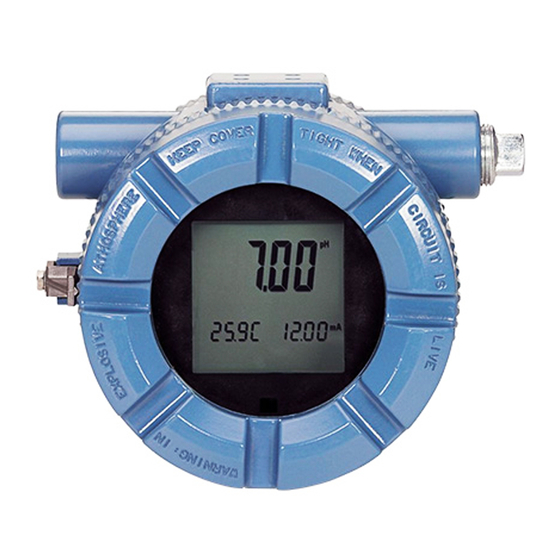
Display and operation Display and operation User interface and main display The following are examples of the main (process) display screen (Figure 5-1) and the program display screen (Figure 5-2). Figure 5-1: Main display screen Conductivity value Temperature in °C or °F Instruction Manual... -
Page 30: Infrared Remote Control (Irc)
Display and operation Figure 5-2: Program display screen Indicates HART or FOUNDATION Fieldbus digital communiciations Conductivity value Units of display Active menu: CALIBRATE, PROGRAM, or DIAGNOSE Sub-menus, prompts, and diagnostic messages appear here. Available commands for sub-menus, prompts, or diagnostic messages Appears when transmitter is in hold Appears when a disabling condition has occurred Infrared remote control (IRC) -
Page 31: Menu System
Display and operation Figure 5-3: Infrared remote control (IRC) functions 1. RESET 6. HOLD • End current operation and return to • Access to turn hold readings on or the main display. off. • Changes are not saved. • Does not return the transmitter to factory default settings. - Page 32 Display and operation Table 5-1: Program menu (continued) Displayed item Definition 4 mA current output (setpoint) 20MA 20 mA current output (setpoint) HoLd Current output on hold FAULt Fault condition current output setting Current output dampening time tESt Current output test value tAUtO Automatic temperature compensation tMAn...
- Page 33 Display and operation Instruction Manual...
- Page 34 Display and operation Rosemount 5081...
- Page 35 Display and operation Figure 5-6: HART contacting conductivity menu tree HART Contacting conductivity menu tree CALIbrAtE Process display screen SEnSOr 0 tEMP AdJ 5000 µS/cm CALIBRATION Mtr CAL 25.0C 12.00mA CELL COnSt CAL key PROG key tEMP SLOPE DIAG key HOLD key OUtPUt CAL OutPut...
- Page 36 Display and operation Figure 5-7: HART toroidal conductivity menu tree HART toroidal conductivity menu tree Model 5081T-HT CALIbrAtE Process Display Screen SEnSOr 0 5000 µS/cm tEMP AdJ CALIBRATION 25.0C 12.00mA CELL COnSt CAL key PROG key tEMP SLOPE DIAG key HOLD key OUtPUt CAL OutPut...
- Page 37 Display and operation Instruction Manual...
- Page 38 Display and operation Rosemount 5081...
- Page 39 Display and operation Instruction Manual...
- Page 40 Display and operation Figure 5-11: FOUNDATION Fieldbus contacting conductivity menu tree Foundation Fieldbus contacting conductivity menu tree CALIbrAtE Process display screen SEnSOr 0 tEMP AdJ 5000 µS/cm CALIBRATION 25.0 C Mtr CAL CAL key PROG key CELL COnSt DIAG key HOLD key tEMP SLOPE tEMP...
- Page 41 Display and operation Figure 5-12: FOUNDATION Fieldbus toroidal conductivity menu tree Foundation Fieldbus toroidal conductivity menu tree CALIbrAtE SEnSOr 0 5000 µS/cm tEMP AdJ CALIBRATION 25.0C 12.00mA CELL COnSt CAL key PROG key tEMP SLOPE DIAG key HOLD key tEMP dISPLAY Process Display PROGRAM...
- Page 42 Display and operation Rosemount 5081...
-
Page 43: Chapter 6 Programming - Basics
Programming - basics Programming - basics 5081 programming The following can be programmed in the 5081: 4-20 mA outputs Current generated by the transmitter during hold Current generated by the transmitter when fault is detected Automatic temperature correction (enable or disable) Type of measurement Measurement range Factory default setting... - Page 44 Programming - basics Use the arrow keys to change the setting. Press ENTER to save. The screen displays the HOLD prompt. Use the arrow keys to change the setting to the output desired when the transmitter is in hold mode. The range is 3.80 to 22.0 mA.
-
Page 45: Temperature Correction
Programming - basics Use the arrow keys to change the setting. The range is 0 to 225. Press ENTER to save. The screen displays the TEST prompt. Use the arrow keys to enter the desired test current. Press ENTER to start the test. Press EXIT to end the test. -
Page 46: Set Up Custom Curves (Conductivity Measurements Only)
Programming - basics Use the arrow keys to change to the desired temperature. To enter negative numbers, press the left or the right arrow key until no digit is flashing. then press the up or down arrow keys to display the negative sign. The range is -5.0 to 130 °C. -
Page 47: Restore To Default Factory Settings
Programming - basics Press ENTER. T REF appears. If needed, change the reference temperature from the factory default 77 °F (25 °C) to a different reference temperature for the process. Press ENTER. UNIT appears. Press the up or down arrow to select the desired measurement units: uS (microsiemens), mS (millisiemens), none (no units displayed), % (percent), or ppm (parts per million);... -
Page 48: Setting Access (Security) Code
Programming - basics Setting access (security) code 6.6.1 Security overview The access (security) code prevents program and calibration settings from accidental changes. The transmitter is shipped with the access (security) code disabled. 6.6.2 Entering the access (security) code If calibration and program settings are protected with a security code, press PROG or CAL on the infrared remote controller. -
Page 49: Activating Or Deactivating Hold
Programming - basics 6.7.2 Activating or deactivating HOLD Press HOLD on the remote controller. The HOLD prompt appears in the display. Press 3 (up) or 5 (down) to toggle HOLD between ON and OFF. Press ENTER to save. Instruction Manual... - Page 50 Programming - basics Rosemount 5081...
-
Page 51: Chapter 7 Measurements
Measurements Measurements Calibrating pH sensors 7.1.1 Calibration overview The calibration menu allows you to calibrate the pH and temperature response of the sensor. Calibrations can be performed using the manual or the auto-calibration option. In both cases, the transmitter does a two-point calibration for pH and one-point standardization against a reference thermometer for temperature. - Page 52 Measurements Procedure Press CAL on the IRC to enter the CALIBRATE menu. The CALIBRATE sub-menu appears. At the CALIBRATE sub-menu, press ENTER. The CAL bF1 prompt appears. Rinse the sensor and place it in the first buffer. Be sure the glass bulb and the temperature element are completely submerged.
-
Page 53: Manual Calibration
Measurements 7.1.4 Manual calibration Prerequisites Ensure that auto-calibration is OFF and the appropriate buffers are used. Procedure Enter the CALIBRATE menu by pressing CAL on IRC. The CALIBRATE sub-menu appears. At the CALIBRATE sub-menu, press ENTER. The CAL BF1 prompt appears. Rinse the sensor with DI water and place it in the first buffer along with a calibrated thermometer. -
Page 54: Standardization For Ph
Measurements 7.1.5 Standardization for pH Standardization overview Standardization is used to match the transmitter values with that of another transmitter. The difference between the two pH values is converted into an equivalent voltage, called the reference offset. Note If a sensor that has been calibrated with buffers is standardized, then placing it back in the buffer will show a different measured pH than that of the buffer due to the standardization offset. -
Page 55: Calibrating Orp Sensors
Measurements Calibrating ORP sensors 7.2.1 ORP overview ORP is a function of temperature. The accuracy of a sensor/transmitter loop is about ± 1 °C. A new sensor does not need to be calibrated often. Only calibrate the loop when: ± 1 °C is not acceptable. Suspected error in temperature measurement 7.2.2 Calibrating temperature with an ORP sensor... -
Page 56: Standardization
Measurements 7.2.3 Standardization Preparation of ORP standard solutions ASTM d 1498-93 gives procedures for making iron (ii) - iron (iii) and quinhydrone ORP standards. The iron (ii) - iron (iii) standard is recommended. It is fairly easy to make and has a shelf life of approximately one year;... -
Page 57: Zeroing The Sensor
Measurements The CALIBRATE submenu appears. Place the sensor in a standard solution of known conductivity and allow the measurement reading to become relatively stable. Press ENTER to access the CAL segment with the flashing prompt. Use the IRC editing keys to enter the conductivity value of the standard solution. Press ENTER. -
Page 58: Output Calibration
Measurements b. Bases: 1.8% to 2.2% per °C c. Salts: 2.2% to 3.0% per °C d. Water: 2.0% per °C Press ENTER to proceed to the T SLOPE submenu with the flashing prompt. Use the IRC keys to generate the desired slope value. Press ENTER. Press EXIT to return to the main screen. -
Page 59: Air Calibration Procedure (Dissolved Oxygen)
Measurements Place the sensor in a solution of 5% sodium sulfite (Na ) in water. Ensure that air bubbles are not trapped against the membrane. Go to the main display; press DIAG and then NEXT. The SENSOR CUR prompt appears. Press ENTER to view the sensor current. -
Page 60: In-Process Calibration Procedure (Dissolved Oxygen)
Measurements The SENSOR CAL submenu appears. Press ENTER. The AIR CAL prompt appears. Press ENTER. Select the units. Then press NEXT. Use the arrow keys to enter the barometric pressure. Press ENTER when done. The TIME DELAY message appears and remains until the sensor reading is relatively stable. -
Page 61: Full Scale Calibration Procedure (Free Chlorine, Total Chlorine, Ozone)
Measurements 7.4.5 Full scale calibration procedure (free chlorine, total chlorine, ozone) Place the sensor in the process liquid. Ensure that the pH sensor is calibrated or the pH value is entered in case of manual pH correction, if applicable. Adjust the chlorine concentration until it is near the upper end of the control range. Wait until the reading is relatively stable before starting the calibration. - Page 62 Measurements Adjust the concentration of chlorine until it is near the top end of the range. Press ENTER. The TIME DELAY message appears and will remain until the sensor reading is relatively stable. To bypass the time delay, press ENTER. The GRAB SPL prompt appears.
-
Page 63: Diagnostics And Troubleshooting
Diagnostics and troubleshooting Diagnostics and troubleshooting pH/ORP diagnostics and troubleshooting 8.1.1 5081-P warning and fault messages The 5081-P pH/ORP transmitter continuously monitors the measurement loop (sensor and transmitter) for conditions that cause erroneous measurements. When a problem occurs, the transmitter displays either a warning or fault message. A warning alerts you that a potentially system disabling condition exists. -
Page 64: Calibration Errors
Diagnostics and troubleshooting If the transmitter is in Hold when the fault occurs, the output remains at the programmed hold value. To alert you that a fault exists, the word FAULT appears in the main display, and the display flashes. A fault or diagnostic message also appears. If the transmitter is simulating an output current when the fault occurs, the transmitter continues to generate the simulated current. -
Page 65: Troubleshooting When A Diagnostic Message Is Showing
Diagnostics and troubleshooting 8.1.4 Troubleshooting when a diagnostic message is showing The 5081-P pH/ORP transmitter continuously monitors the measurement loop (sensor and transmitter) for problems. If a problem is detected, the transmitter displays a fault or error message. The message appears in the temperature/output area of the main display. The table lists each diagnostic message and the section to consult for help. - Page 66 Diagnostics and troubleshooting NOTICE GLASSFAIL is a sensor diagnostic message. Sensor diagnostic messages are optional. They can be turned off. Troubleshooting flowchart - GLASSFAIL Be sure the sensor is completely immersed in the process liquid. If the diagnostic message disappears, the sensor is in good condition. If the diagnostic message remains, go to Step 2.
- Page 67 Diagnostics and troubleshooting c. For Rosemount PLUS (+) and TUpH sensors that do not have an integral preamplifier, attach the blue solution ground wire to TB-8 or, better, leave the blue wire unattached and jumper TB-7 to TB-8. d. If the sensor does not have a blue solution ground wire, jumper terminals TB-7 and TB-8.
-
Page 68: Glasswarn
Diagnostics and troubleshooting If cleaning the sensor lowers the impedance below 800 megohms... a. The sensor is in good condition. b. Return the calibrated sensor to service. If cleaning does not lower the glass impedance and the sensor can be calibrated... -
Page 69: Ref Fail
Diagnostics and troubleshooting rEF FAIL rEF FAIL is an electrode fault message. rEF FAIL means that the reference impedance exceeds the programmed reference high fault (RFH) limit. A plugged or dry reference junction is the usual cause of a high reference impedance. High reference impedance also occurs if the sensor is not submerged in the process liquid or if inappropriate limits have been entered into the transmitter. -
Page 70: Ref Warn
Diagnostics and troubleshooting b. Inspect and clean the sensor. If the sensor is rebuildable, replace the reference junction and replenish the electrolyte solution. Refer to the sensor instruction manual for details. Check the reference impedance again. If cleaning the sensor reduces the impedance... a. -
Page 71: Calibrate
Diagnostics and troubleshooting CALIbrAtE CALIbrAte is a diagnostic intended for future use. If the CALIbrAte message is showing, disable CALIbrAte. tEMP HI and tEMP LO tEMP HI and tEMP LO mean the transmitter has detected a problem with the temperature measuring circuit. - Page 72 Diagnostics and troubleshooting Figure 8-3: Three-wire RTD Consult the table for resistance-temperature data. Lead resistance is about 0.05 ohm/ft at 25 °C. Therefore, 15 feet of cable increases the resistance by about 1.5 ohm. The resistance between the RTD return and RTD sense leads should be less than 2 ohms. Table 8-1: RTD resistance values Temperature...
-
Page 73: Line Fail
Diagnostics and troubleshooting Figure 8-4: Temperature simulation into the 5081-P pH/ORP transmitter • If the measured temperature is correct, the transmitter is working properly. • If the measured temperature is incorrect, calibrate the transmitter against the standard resistance equivalent to 25 °C (77 °F). Change the resistance and verify that the temperature reading changes to the correct value. -
Page 74: Input Warn
Diagnostics and troubleshooting • If the diagnostic message disappears, either the RTD return or RTD sense wire is broken. To verify a broken wire, disconnect the leads and measure the resistance between them. Installing the jumper completes the circuit, but bypasses the three-wire function. -
Page 75: Slope Err Lo
Diagnostics and troubleshooting • If the message remains, go to Step 4. Confirm that the problem is with the remote preamplifier. Wire the pH sensor directly to the transmitter. Change the menu from PAMP=SnSr to trAnS for the test and return it to SnSr afterwards. •... -
Page 76: Slope Err Hi
Diagnostics and troubleshooting If the glass impedance is less than about 20 megohms, the glass has cracked and the electrode must be replaced. If the glass impedance is greater than about 20 megohms, the sensor is probably in good condition. Go to Step 5. Check transmitter performance by simulating pH inputs. -
Page 77: Std Err
Diagnostics and troubleshooting if the transmitter responds to simulated inputs, the problem must lie with the sensor or the interconnecting wiring. Verify the interconnecting wiring point to point. Fix or replace bad cable. If cable is good, replace the pH sensor. Std Err Std Err means the reference electrode voltage has changed drastically. -
Page 78: Fact Fail Error Message
Diagnostics and troubleshooting Troubleshooting WritE Err Check the position of jumper JP1 on the CPU board. If the jumper is hanging off one of the pins, place it across both pins. If the jumper is missing entirely, use jumper JP3 (50/60 Hz), which is not a critical jumper. -
Page 79: Id000 In Display
Diagnostics and troubleshooting Symptom Section Display segments missing or display incorrect Display segments missing Transmitter locked up, all display segments lit Transmitter locks up Transmitter periodically restarts itself Transmitter periodically restarts itself. Id000 in display A security code has been programmed into the transmitter. The correct code must be entered before the transmitter can be programmed or calibrated. -
Page 80: Ph Reading In Buffer Drifts During Manual Calibration
Diagnostics and troubleshooting Check the stability limits. If the stabilization range (prompt PH) is set too narrow or the stabilization time (prompt tIME) is set too long, the transmitter will not accept buffer readings. A good choice for PH is 0.02, and a good choice for tIME is 10 - 20 seconds. -
Page 81: Buffer Calibration Is Acceptable; Process Ph Is Slightly Different From Expected Value
Diagnostics and troubleshooting Buffer calibration is acceptable; process pH is slightly different from expected value Differences between pH readings made with an on-line instrument and a laboratory or portable instrument are normal. The on-line instrument is subject to process variables, for example, ground potentials, stray voltages, and orientation effects, that do not affect the laboratory or portable instrument. -
Page 82: Temperature Reading Is Inaccurate
Diagnostics and troubleshooting c. Connect a jumper wire between TB-3 (RTD RTN) and TB-4 (RTD-SNS). Connect a second jumper wire between TB-7 (REF IN) and TB-8 (SOL GND). d. Place the sensor back in the process liquid. If diagnostic measures such as GLASSFAIL or REF WArn appear, turn off the sensor diagnostics. -
Page 83: No Display
Diagnostics and troubleshooting c. For HART communications, the power supply voltage must be at least 18 Vdc. Be sure the HART communicator is properly connected. a. The communicator leads must be connected across the load. b. The communicator can be connected across the power terminals (TB-15 and TB-16). -
Page 84: Displaying Diagnostic Variables
Diagnostics and troubleshooting b. Try connecting the transmitter to a different power supply. 8.1.6 Displaying diagnostic variables Purpose This section describes how to display the diagnostic variables listed below: Diagnostic measurements Sensor voltage in mv (InPut) Glass impedance in megohms (GIMP) Reference temperature in kilohms (rIMP) Temperature in °C Diagnostic messages... -
Page 85: Testing The Transmitter By Simulating The Ph
Diagnostics and troubleshooting Press NEXT. The ShoW Fit submenu appears. Press ENTER. The most recent fault message appears in the display. Press NEXT repeatedly to scroll through the stored messages. The transmitter only remembers the three most recent messages. nonE appears if there are no faults. - Page 86 Diagnostics and troubleshooting Disconnect the sensor and wire transmitter as shown in Figure 8-5. Attach a jumper between TB-7 (REF IN) and TB-10 (pH IN). Measure the voltage. Press DIAG on the IRC. The InPut voltage in millivolts appears in the temperature-output area. The main display continues to show pH.
-
Page 87: Ph Simulation When The Preamplifer Is Located In A Remote Junction Box Or In A Sensor-Mounted Junction Box
Diagnostics and troubleshooting Figure 8-5: pH simulation when the preamplifier is located in the transmitter pH simulation when the preamplifer is located in a remote junction box or in a sensor-mounted junction box Program PAMP to sensor. Turn off sensor diagnostics. Turn off automatic temperature compensation. -
Page 88: Ph Simulation With 381+ Sensor
Diagnostics and troubleshooting Figure 8-6: pH simulation when the preamplifier is located in a remote junction box or in a sensor mounted junction box pH simulation with 381+ sensor Verify that switch s-1 is set to sensor or junction box. Turn off sensor diagnostics. - Page 89 Diagnostics and troubleshooting Figure 8-7: Simulate pH through 381+ sensor preamplifier A. Cover P/N 23552-00 B. Glass electrode cable C. Preamp BNC connector D. To center conductor of BNC E. Power supply or millivolt source F. Reference electrode G. Jumper wire H.
- Page 90 Diagnostics and troubleshooting T.C. element connections Preamplifier P/N 23561-00 K. Sensor cable connector Important Do not connecto anything to outside of preamp BNC connector. Touch the other end of the second jumper to the center pin of the BNC connector on the preamplifier.
-
Page 91: Ph Simulation When Preamplifier Is In Sensor
For assistance in correcting transmitter, sensor, and measurement problems... • In the United States, call Emerson Liquid Division at 800 854 8257 • Outside the United States, call the nearest Emerson office. See the back page of the manual. Contacting and toroidal conductivity diagnostics and troubleshooting 8.2.1... -
Page 92: Fault Conditions
Diagnostics and troubleshooting Table 8-2: Diagnostic variables mnemonics Absolute conductivity (µS/cm or mS/cm) 0 A ir Sensor zero in air CELL ConSt Sensor cell constant (used in C mode) tSLOPE Temperature slope in %/° C CAL F Calibration factor SoFt Software version HArd Hardware version... -
Page 93: Non-Disabling Warnings
Diagnostics and troubleshooting Figure 8-8: Disabling fault annunciation Non-disabling warnings When a non-system-disabling condition occurs, a warning message is displayed. The process variable does not flash. The appropriate message alternates with the Temperature/Current output display (see Figure 8-9). If more than one fault exists, the display will sequence through each diagnostic message. This will continue until the cause of the fault has been corrected. -
Page 94: Quick Troubleshooting Guide
Diagnostics and troubleshooting Table 8-3: Diagnostic fault messages Message Description Action Faults tEmP LO Temperature is too low. Check wiring or sensor/process temp. Check RTD. tEmP HI Temperature is too high. Check wiring or sensor/process temp. Check RTD. rtd FAIL The RTD sensor line fault limits have been ex- Check wiring or Check Pro- ceeded for the sensor. -
Page 95: Field Troubleshooting
Diagnostics and troubleshooting Table 8-4: Quick troubleshooting guide Symptom Action Wrong temperature reading. Perform a temperature standardization. Verify sensor's RTD. Suspected temp. compensation problem. Resistance vs. temp. Check wiring. Display segments missing. Display inoperable. Replace display board. Analyzer locks up; won't respond. Replace PCB stack. -
Page 96: Systematic Troubleshooting
Diagnostics and troubleshooting To troubleshoot the transmitter independently of the sensor, use an appropriate resistor across the temperature input connectors and connect the conductivity inputs to resistance decade box. 8.2.5 Systematic troubleshooting If the quick troubleshooting guide does not resolve the error, try the step-by-step approach offered in in the flowchart below. -
Page 97: 5081C Warning And Fault Messages
Diagnostics and troubleshooting Figure 8-10: Conductivity determination Use the following formula to determine the appropriate resistance value to use to simulate a conductivity value. 8.2.7 5081C warning and fault messages The 5081 transmitter continuously monitors the sensor and transmitter for conditions that cause erroneous measurements. -
Page 98: Troubleshooting Contacting And Toroidal Conductivity Analyzers When A Fault Or Warning Message Is Showing
Diagnostics and troubleshooting If the transmitter is simulating an ouput current when the fault occurs, the transmitter continues to generate the simulated current. To alert you that a fault exists, the word FAULT appears in the main display, and the display flashes. 8.2.8 Troubleshooting contacting and toroidal conductivity analyzers when a fault or warning message is showing... -
Page 99: Cal Error
Diagnostics and troubleshooting SEnSor FAIL may appear for a while when the sensor is first placed in service. Procedure Observe the sensor current (go to SEnSor Cur under the Diagnostic menu). If the sensor is moving in the positive direction, there is probably nothing wrong, and the error message should soon disappear. -
Page 100: Sense Open
Diagnostics and troubleshooting Measure the resistance between the RTD IN and RETURN leads. For a thermistor, measure the resistance between the two leads. If the temperature is open or shorted, replace the sensor. In the meantime, use manual temperature compensation. SenSE OPEn Most Rosemount sensors use a Pt100 or Pt1000 in a three-wire configuration. -
Page 101: Fact Fail Procedure
Diagnostics and troubleshooting FAct FAIL procedure FACt FAIL appears if the transmitter factory calibration message has been triggered. A stray noise spike can cause this message to appear. If the pH reading seems acceptable, reset the calibration flag. Enter the factory calibration menu by pressing 2 on the IRC ten times. The display does not change. -
Page 102: Cpu Fail And Rom Fail
Diagnostics and troubleshooting CPU FAIL and ROM FAIL CPU FAIL means that the processing unit has failed internal tests. ROM FAIL means that the internal memory has failed. Cycle the power. Leave the transmitter off for at least 30 seconds before returning power to it. -
Page 103: Diagnostic Messages For Ozone And Total Chlorine
Diagnostics and troubleshooting FAULtS Press ENTER to scroll through existing fault messages. 8.3.3 Diagnostic messages for ozone and total chlorine TYPE O3 or tCL Transmitter is measuring ozone (or total chlorine). Press NEXT to view diagnos- tics. SEnSor Cur Press ENTER to display raw current from sensor (note units). SEnSitvtY Press ENTER to display sensitivity. -
Page 104: Troubleshooting Fault Or Warning Messages
Diagnostics and troubleshooting There is a high probability that the measurement is in error. A fault alerts you that a disabling condition exists. If a fault message is showing, all measurements should be regarded as erroneous. When a warning condition exists: The main display remains stable. -
Page 105: Bad Sensor
Diagnostics and troubleshooting Message Explanation See section bAd rtd Bad temperature reading bAd rtd, TEMP HI, TEMP LO, and rtd OPEn TEMP HI Temperature reading exceeds 150 °C (302 °F) bAd rtd, TEMP HI, TEMP LO, and rtd OPEn TEMP LO Temperature reading is less than -15 °C (5 °F) bAd rtd, TEMP HI, TEMP LO, and rtd OPEn... -
Page 106: Too Big
Diagnostics and troubleshooting See the sensor instruction sheet for details. Replace the sensor. 0 too bIG Normally, the transmitter will not accept a zero current until the current has fallen below a reasonable value. See the calibration section for the analyte being determined for zero currents. -
Page 107: Slope Hi Or Slope Lo
Diagnostics and troubleshooting Replace the sensor. SLOPE HI or SLOPE LO Once the two-point (manual or automatic) pH calibration is complete, the transmitter automatically calculates the sensor slope at 25 °C. If the slope is greather than 62 mV/pH, the transmitter displays the SLOPE HI error. If the slope is less than 45 mV/pH, the transmitter displays the SLOPE LO error. -
Page 108: Adc
Diagnostics and troubleshooting A large standardization offset may be caused by a poisoned reference electrode. Poisoning agents can cause the pH to be offset by as much as two pH units. To check the reference voltage, see Section 8.4.13. AdC means the analog to digital converter has failed. Verify that the sensor wiring is correct and connections are tight. -
Page 109: Temperature Measurement And Calibration Problems
Diagnostics and troubleshooting 8.4.3 Temperature measurement and calibration problems Temperature different from transmitter Is the standard thermometer, RTD, or thermistor accurate? General purpose liquid- in glass thermometers, particularly ones that have been mistreated, can have suprisingly large errors. Is the temperature element in the sensor completely submerged in the liquid? Is the standard temperature sensor submerged to the correct level? 8.4.4 Oxygen measurement and calibration problems... -
Page 110: Zero Reading Unstable
Diagnostics and troubleshooting Is the zero solution fresh and properly made? Zero the sensor in a solution of 5% sodium sulfite in water. Prepare the solution immediately before use. It has a shelf life of only a few days. If the sensor is being zeroed with nitrogen gas, verify that the nitrogen is oxygen- free and the flow is adequate to prevent back-diffusion of air into the chamber. -
Page 111: Process And Standard Readings Different
Diagnostics and troubleshooting Is the membrane dry? The membrane must be dry during air calibration. A droplet of water on the membrane during air calibration will lower the sensor current and cause an inaccurate calibration. If the sensor current in air is very low and the sensor is new, either the electrolyte flow has stopped or the membrane is torn or loose. -
Page 112: Readings Drift
Diagnostics and troubleshooting Readings drift. Is the membrane clean? For the sensor to work properly, oxygen must diffuse freely through the membrane. A coating on the membrane will interfere with the passage of oxygen, resulting in a slow response. Is the sensor in direct sunlight? If the sensor is in direct sunlight during air calibration, readings will drift as the sensor warms up. -
Page 113: Free Chlorine Measurement And Calibration Problems
Diagnostics and troubleshooting 8.4.5 Free chlorine measurement and calibration problems Problem See Section Zero current is substantially outside the range -10 to 10 nA. Zero current outside range Zero reading is unstable. Chlorine zero reading unstable Sensor current during calibration is substantially less than Sensor current too low about 350 nA/ppm at 25 °C (77 °F) and pH 7. -
Page 114: Sensor Current Too Low
Diagnostics and troubleshooting If shaking does not work, try clearing the holes around the cathode stem. Hold the sensor with the membrane end pointing up. Unscrew the membrane retainer and remove the membrane assembly. Be sure the wood ring remains with the membrane assembly. -
Page 115: Chlorine Readings Drift
Diagnostics and troubleshooting Chlorine readings drift Is the sample temperature changing? Membrane permeability is a function of temperature. The time constant for the 499ACL-01 sensor is about five minutes. Therefore, the reading may drift for a while after a sudden temperature change. Is the membrane clean? For the sensor to work properly, chlorine must diffuse freely through the membrane. -
Page 116: Chlorine Readings Too Low
Diagnostics and troubleshooting Chlorine readings too low Was the sample tested as soon as it was taken? Chlorine solutions are unstable. Test the sample immediately after collecting it. Avoid exposing the sample to sunlight. Low readings can be caused by zeroing the sensor before the residual current has reached a stable minimum value. -
Page 117: Ozone Zero Reading Unstable
Diagnostics and troubleshooting Has adequate time been allowed for the sensor to reach a minimum stable residual current? It may take several hours, sometimes as long as overnight, for a new sensor to stabilize. Check the membrane for damage and replace it if neccessary. Ozone zero reading unstable Is the sensor properly wired to the transmitter? Verify that all wiring connections are tight. -
Page 118: Ozone Process Readings Erratic
Diagnostics and troubleshooting Ozone process readings erratic If the ozone process readings are erratic, see the information below. Readings are often erratic when a new sensor or a rebuilt sensor is first placed in service. The current usually stabilizes after a few hours. Is the sample flow within the recommended range? High sample flow may cause erratic readings. -
Page 119: Ph Measurement And Calibration Problems
Diagnostics and troubleshooting Low readings can be caused by zeroing the sensor before the residual current has reached a stable minimum value. Residual current is the current the sensor generates even when no ozone is in the sample. Because the residual current is subtracted from subsequent measured currents, zeroing before the current is a minimum can lead to low results. -
Page 120: Sensor Not Responding To Ph Changes
Diagnostics and troubleshooting Sensor not responding to pH changes Did the expected pH change really occur? If the process pH reading was not what was expected, check the performance of the sensors in buffers. Also, use a second pH meter to verify the change. Is the sensor properly wired to the transmitter? Is the glass bulb cracked or broken? Check the glass electrode impedance. -
Page 121: Process Readings Noisy
Diagnostics and troubleshooting a. The measurement system needs one path to ground: through the process liquid and piping. Plastic piping, fiber-glass tanks, and ungrounded or poorly grounded vessels do not provide a path. A floating system can pick up stray voltages from other electrical equipment. -
Page 122: Simulating Input Currents - Dissolved Oxygen
Diagnostics and troubleshooting Is the sensor properly wired to the transmitter? Is a ground loop present? Refer to Process pH grossly wrong or noisy 8.4.9 Simulating input currents - dissolved oxygen To check the performance of the transmitter, use a decade box to simulate the current from the oxygen sensor. -
Page 123: Simulating Input Currents - Chlorine And Ozone
Diagnostics and troubleshooting Change the decade box resistance and verify that the correct current is shown. Calculate the current from the equation: 8.4.10 Simulating input currents - chlorine and ozone To check the performance of the transmitter, use a decade box and a battery to simulate the current from the sensor. -
Page 124: Simulating Inputs - Ph
Diagnostics and troubleshooting c. Press ENTER. The display shows the sensor current. d. Note the units µA is microamps; na is nanoamps. Change the decade box resistance and verify that the correct current is shown. Calculate the current from the equation: The voltage of a fresh 1.5 volt battery is about 1.6 volt (1600 mV). - Page 125 Diagnostics and troubleshooting The second line of the display shows the pH. The pH should be approximately 7.00. Because calibration data stored in the analyzer may be offsetting the input voltage, the displayed pH may not be exactly 7.00 If a standard millivolt source is available, disconnect the jumper wire between the pH IN and REF IN terminals and connect the voltage source as shown in Figure 8-13.
-
Page 126: Preamplifier In A Junction Box
Diagnostics and troubleshooting Voltage (mV) pH (at 25 °) 295.8 2.00 177.5 4.00 59.2 6.00 59.2 8.00 177.5 10.00 295.8 12.00 Preamplifier in a junction box The procedure is the same as described in Preamplifier in transmitter. Keep the connection between the analyzer and the junction box in place. -
Page 127: Simulating Temperature Procedure
Diagnostics and troubleshooting Figure 8-14: Three-wire RTD configuration Although only two wires are required to connect the RTD to the analyzer, using a third wire allows the analyzer to correct for the resistance of the lead wires and for changes in the lead wire resistance with temperature. -
Page 128: Measuring Reference Voltage
Diagnostics and troubleshooting For example, start with a simulated resistance of 103.9 Ω, which corresponds to 10.0 °C (50 °F). Assume that the offset from the sensor calibration was -0.3 Ω. Because of the offset, the analyzer calculates temperature using 103.6 Ω. The result is 9.2 °C. Now change the resistance to 107.8 Ω, which corresponds to 20.0 °C (68 °F). - Page 129 Diagnostics and troubleshooting Figure 8-16: Checking for a poisoned reference electrode Refer to the sensor wiring diagram to identify the reference leads. A laboratory silver/silver chloride electrode can be used in place of the second sensor. Instruction Manual...
- Page 130 Diagnostics and troubleshooting Rosemount 5081...
-
Page 131: Chapter 9 Digital Communications
Digital communications Digital communications HART communications 9.1.1 Overview of HART communication HART (highway addressable remote transducer) is a digital communication system in which two frequencies are superimposed on the 4 to 20 mA output signal from the transmitter. A 1200 Hz sine wave represents the digit 1, and a 2400 Hz sine wave represents the digit 0. -
Page 132: Foundation Fieldbus Communication
Digital communications Figure 9-1: HART communicators Model 5081-C-HT two-wire transmitter Handheld communicator (configurator) 4-20 mA + digital Bridge Control system Computer Both the Rosemount Model 375 (or 475) and a computer can be used to communicate with a HART transmitter. The 250 ohm load (minimum) must be present between the transmitter and the power supply. -
Page 133: Foundation Fieldbus Specifications
Digital communications Figure 9-2: Configuring Model 5081-C transmitter with Foundation Fieldbus Terminator DeltaV configurator and host 5081-C-FF Sensor Fieldbus technician configurator Process line Other host Terminator Filter Power supply 9.2.1 Foundation Fieldbus specifications Model 5081-C-FF Fieldbus Transmitter Type Contacting conductivity transmitter Device ITK profile 6 (released for (ITK 6.0.0/6.0.1) Manufacturer identification (MANUFAC_ID) -
Page 134: Asset Management Solutions
Digital communications Mandatory features • Resource block • Alarm and events • Function block linking • Trending • Multi-bit alert reporting • Field diagnostics Additional features • Common software download • Block instantiation • Supports DeltaV auto commissioning • Supports DeltaV auto replacement •... - Page 135 Digital communications AMS can play a central role in plant quality assurance and quality control. Using AMS Audit Trail, plant operators can track calibration frequency and results as well as warnings and diagnostic messages. The information is available to Audit Trail whether calibrations were done using the infrared remote controller, the 375 HART communicator, or AMS software.
- Page 136 Digital communications Rosemount 5081...
-
Page 137: Chapter 10 Return Of Material
Carefully package the materials and enclose your Letter of Transmittal. If possible, pack the materials in the same manner as they were received. Send the package prepaid to: Emerson Automation Solutions Rosemount c/o A.F. Romero 1749 Stergios Road... - Page 138 Return of material NOTICE Consult the factory for additional information regarding service or repair. Rosemount 5081...
-
Page 139: Appendix A Engineering Drawings
Engineering drawings Appendix A Engineering drawings The following is a list of engineering drawings in the order in which they appear in the manual. Drawing number Title 1400674 Schem, CSA I.S. / NIFW installation 5081 C/T 1400675 Schem, CSA I.S. / NIFW install 5081 P/A 1400676 Schem, FM I.S. - Page 140 Engineering drawings Rosemount 5081...
- Page 141 Engineering drawings Instruction Manual...
- Page 142 Engineering drawings Rosemount 5081...
- Page 143 Engineering drawings Instruction Manual...
- Page 144 Engineering drawings Rosemount 5081...
- Page 145 Engineering drawings Instruction Manual...
- Page 146 Engineering drawings Rosemount 5081...
-
Page 147: Appendix B Eu Declarations Of Conformity
EU Declarations of Conformity Appendix B EU Declarations of Conformity The following pages are the EU Declarations of Conformity for the 5081-T, 5081 P/A, and 5081-C. Instruction Manual... -
Page 148: Eu Declaration Of Conformity
EU Declaration of Conformity (No. 1700908) 5081-T This declaration is issued under the sole responsibility of the manufacturer: Rosemount Inc., 8200 Market Blvd., Chanhassen, MN 55317 USA The product, Rosemount Toroidal Conductivity Transmitter model 5081-AA-BB-CC-DD Where AA is: CC is: Toroidal conductivity measurement Infrared remote controller included Infrared remote controller not included BB is:... - Page 149 EU Declaration of Conformity (No. 1700906) 5081-P/A… This declaration is issued under the sole responsibility of the manufacturer: Rosemount Inc., 8200 Market Blvd., Chanhassen, MN 55317 USA The product, Rosemount Amperometric/pH Transmitter model 5081-AA-BB-CC-DD Where AA is: CC is: pH/ORP Measurement Infrared remote controller included Amperometric (oxygen, ozone, chlorine) Infrared remote controller not included...
- Page 150 EU Declaration of Conformity (No. 1700907) 5081-C This declaration is issued under the sole responsibility of the manufacturer: Rosemount Inc., 8200 Market Blvd., Chanhassen, MN 55317 USA The product, Rosemount Contacting Conductivity Transmitter model 5081-AA-BB-CC-DD Where AA is: CC is: Contacting Conductivity measurement Infrared remote controller included Infrared remote controller not included...
- Page 151 EU Declarations of Conformity Rosemount 5081...
- Page 152 2017 Emerson. All rights reserved. youtube.com/RosemountMeasurement The Emerson logo is a trademark and service mark of Emerson Electric Co. Rosemount is a google.com/+RosemountMeasurement mark of one of the Emerson family of companies. All other marks are the property of their AnalyticExpert.com respective owners.