Table of Contents
Advertisement
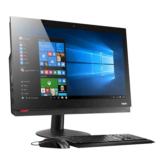
M910z
User Guide and
Hardware Maintenance Manual
Machine Type (MT):
10NR, 10NS, 10NT, 10NU
Energy Star MT:
10NR, 10NS, 10NT, 10NU
Overview
Locations of indicators,
connectors, and
controls provided on
your computer
Replaceable parts
Locations of the
replaceable parts on
your computer
Computer locks
Locking devices to keep
your computer safe
Replacing CRUs
Replacing instructions
for customer-
replaceable units
(CRUs)
Specifications
Specifications of your
computer
Replacing FRUs
Replacing instructions
for field-replaceable
units (FRUs) (for
technicians only)
Advertisement
Table of Contents

Related Manuals for Lenovo ThinkCentre M910z


Summary of Contents for Lenovo ThinkCentre M910z
- Page 1 M910z User Guide and Hardware Maintenance Manual Machine Type (MT): 10NR, 10NS, 10NT, 10NU Energy Star MT: 10NR, 10NS, 10NT, 10NU Overview Computer locks Specifications Locations of indicators, Locking devices to keep Specifications of your connectors, and your computer safe computer controls provided on your computer...
-
Page 2: Table Of Contents
Contents Overview .........3 Replacing the memory module .......30 Completing the parts replacement ......32 Front view ............... 3 Rear view ................ 5 Replacing FRUs ......33 System board ..............7 Adjusting the monitor stand........9 Before replacing FRUs ..........33 Adjusting the UltraFlex II Stand ......... 9 Replacing the computer cover and side I/O bezel ...............36 Machine type and model label .........10... -
Page 3: Overview
Overview Front view Note Your computer model might look slightly different from the illustration. Integrated microphones (2) (optional) Used to record sounds or use speech-recognition software without using a microphone. Integrated camera activity indicator (optional) When the indicator is on, the camera is in use. Integrated camera (optional) Used to take pictures or hold a video conference. -
Page 4: Power Button
Power button Used to turn on your computer. When you cannot shut down the computer from the operating system, press and hold the power button for four or more seconds to turn off the computer. Microphone mute/unmute indicator When the microphone mute/unmute indicator is on, the microphones are muted. -
Page 5: Rear View
Rear view Note Your computer model might look slightly different from the illustration. Integrated camera shield control slider (optional) Used to disable the integrated camera physically. USB 3.0 Type-C connector (optional) Used to connect a USB-compatible device, such as a USB keyboard, mouse, scanner, printer, or personal digital assistant (PDA). - Page 6 USB 3.0 connectors (4) Used to connect a USB-compatible device, such as a USB keyboard, mouse, scanner, printer, or personal digital assistant (PDA). For optimal data transfer, connect a USB 3.0 device to a USB 3.0 connector instead of a USB 2.0 connector.
-
Page 7: System Board
System board Note Front view Rear view for additional component descriptions. LCD power connector Integrated camera connector Microprocessor socket Coin-cell battery M.2 Wi-Fi card slot Memory slot (DIMM2) Memory slot (DIMM1) USB 3.0 Type-C connector Card reader connector M.2 storage drive slot Internal speaker connector LCD panel connector Graphics processor unit (GPU) - Page 8 Control button board connector Touch screen connector Power supply assembly connector SATA connector (for connecting an optical drive) SATA connector (for connecting a storage drive) Power connector (for connecting a storage drive or an optical drive) System fan connector Overview...
-
Page 9: Adjusting The Monitor Stand
Adjusting the monitor stand Note The monitor stand is available only on some models. Adjust the vertical position of the computer between 5° forward and 45° back. Adjusting the UltraFlex II Stand Note The UltraFlex II Stand is available only on some models. Adjust the vertical position of the computer between 5°... -
Page 10: Machine Type And Model Label
Machine type and model label The machine type and model label identifies your computer. When you contact Lenovo for help, the machine type and model information helps support technicians to identify your computer and provide faster service. The machine type and model label is attached on the rear side of your computer as shown. -
Page 11: Computer Locks
Depending on the type selected, the cable lock can be operated with a key or combination. The cable lock also locks the buttons used to open the computer cover. This is the same type of lock used with many notebook computers. You can order such a cable lock directly from Lenovo by searching for Kensington at: http://www.lenovo.com/support. -
Page 12: Specifications
Specifications Power supply • 150 watt automatic voltage-sensing power supply • 180 watt automatic voltage-sensing power supply (optional) Storage drives Up to two storage drives Video features The integrated graphics card supports the DisplayPort in/out connector on your computer. Audio features The integrated audio card supports the following: •... -
Page 13: Replacing Hardware
• In most areas of the world, Lenovo requires the return of defective Customer Replaceable Units (CRUs). Information about this will come with the CRU or will come a few days after the CRU arrives. -
Page 14: Knowing Replaceable Parts
CRU. Optional-service CRUs can be removed and installed by users or, during the warranty period, by a Lenovo service technician. Field-Replaceable Units (FRUs) FRUs are computer parts that a trained technician can upgrade or replace. -
Page 15: Crus And Frus Locations
CRUs and FRUs locations Refer to the following illustrations to check the locations of CRUs and FRUs within the computer. Note Some of the following parts are optional on some models. Self-service CRU Monitor stand base p. 24 Monitor stand p. - Page 16 Optional-service CRU Optical drive holder p. 28 Optical drive p. 28 Optical drive bezel p. 28 Replacing hardware...
-
Page 17: Computer Cover
Computer cover p. 36 Side I/O bezel p. 36 System board shield p. 40 Side I/O bracket p. 40 VESA® mount bracket p. 41 Cover presence switch (intrusion switch) p. 41 Wi-Fi antennas (2) p. 51 Integrated camera p. 39 Integrated camera cable p. -
Page 18: Thermal Sensor
Thermal sensor p. 61 ac-in cable p. 59 Power supply assembly p. 43 LCD panel p. 67 Middle frame p. 67 SATA cables p. 62 System fan p. 46 Control button board p. 38 Control button board bracket p. 38 Control button board cable p. -
Page 19: Replacing Crus
• Before replacing a CRU, ensure that you have read the instructions in the Note sensitive devices. • To replace a component that is not in the list below, contact a Lenovo service technician. The support phone numbers are available at http://www.lenovo.com/support/phone. Keyboard or wireless... -
Page 20: Replacing The Keyboard Or Wireless Keyboard
Replacing the keyboard or wireless keyboard Note The wireless keyboard is available only on some models. Replacing the keyboard Turn off the computer and disconnect all power cords from electrical outlets. Disconnect the old keyboard cable from the computer. Connect a new keyboard to the appropriate connector on the computer. Replacing the wireless keyboard Remove your old wireless keyboard. -
Page 21: Replacing The Mouse Or Wireless Mouse
Replacing the mouse or wireless mouse Note The wireless mouse is available only on some models. Replacing the mouse Turn off the computer and disconnect all power cords from electrical outlets. Disconnect the old mouse cable from the computer. Connect a new mouse to the appropriate connector on the computer. Replacing the wireless mouse Disconnect the USB dongle from your computer. - Page 22 • The green LED indicates that the mouse is ready for use. Note • The flashing amber LED indicates a low battery level. • Push the power switch to the off position when you are not using the mouse to extend the battery life.
-
Page 23: Replacing The Power Cord
Replacing the power cord Do not open your computer or attempt any repairs before reading the Important Attention Product Information Guide. Remove any media from the drives and turn off all connected devices and the computer. Disconnect all power cords from electrical outlets and disconnect all cables that are connected to the computer. -
Page 24: Replacing The Monitor Stand
Replacing the monitor stand Note The monitor stand is available only on some models. Remove any media from the drives and turn off all connected devices and the computer. Disconnect all power cords from electrical outlets and disconnect all cables that are connected to the computer. -
Page 25: Replacing The Ultraflex Ii Stand
Replacing the UltraFlex II Stand Note The UltraFlex II Stand is available only on some models. Remove any media from the drives and turn off all connected devices and the computer. Disconnect all power cords from electrical outlets and disconnect all cables that are connected to the computer. -
Page 26: Removing The Slide Cover
Removing the slide cover Do not open your computer or attempt any repairs before reading the Important Attention Product Information Guide. Before you open the slide cover, turn off the computer and wait several Caution minutes until the computer is cool. Remove any media from the drives and turn off all connected devices and the computer. -
Page 27: Replacing The 2.5-Inch Storage Drive
Replacing the 2.5-inch storage drive Do not open your computer or attempt any repairs before reading the Important Attention Product Information Guide. Remove the computer stand. For details, see Replacing the monitor stand Replacing the UltraFlex II Stand. Remove the slide cover. For details, see Removing the slide cover. ... -
Page 28: Replacing The Optical Drive
Replacing the optical drive Do not open your computer or attempt any repairs before reading the Important Attention Product Information Guide. Remove the computer stand. For details, see Replacing the monitor stand Replacing the UltraFlex II Stand. Remove the slide cover. For details, see Removing the slide cover. ... - Page 29 Reinstall the removed parts and slide cover. For details, see Completing the parts replacement. Replacing CRUs...
-
Page 30: Replacing The Memory Module
Replacing the memory module Do not open your computer or attempt any repairs before reading the Important Attention Product Information Guide. If your computer supports one memory module, install the module into the DIMM 1 slot. If your computer supports two memory modules, install one memory module into the DIMM 1 slot first and then install the other into the DIMM 2 slot. - Page 31 Reinstall the removed parts and slide cover. For details, see Completing the parts replacement. Replacing CRUs...
-
Page 32: Completing The Parts Replacement
Completing the parts replacement After completing the installation or replacement for all parts, reinstall the slide cover and reconnect the cables. To reinstall the slide cover and reconnect the cables to your computer, do the following: Ensure that all components have been reassembled correctly and that no tools or loose screws are left inside your computer. -
Page 33: Replacing Frus
• To check the locations of FRUs, see CRUs and FRUs locations. • To replace a component that is in the list below, contact a Lenovo service technician. The support phone numbers are available at http://www.lenovo.com/support/phone. Computer cover... - Page 34 Integrated camera System board shield Side I/O bracket VESA mount bracket Cover presence switch Power supply assembly Heat sink System fan Coin-cell battery Wi-Fi card Wi-Fi antennas USB 3.0 Type-C connector board Replacing FRUs...
- Page 35 Card reader M.2 storage drive Serial connector module Internal speakers ac-in cables Thermal sensor SATA cables Microprocessor System board LCD panel Replacing FRUs...
-
Page 36: Replacing The Computer Cover And Side I/O Bezel
Replacing the computer cover and side I/O bezel Do not open your computer or attempt any repairs before reading the Important Attention Product Information Guide. Before you open the computer cover, turn off the computer and wait Caution several minutes until the computer is cool. Remove the slide cover. - Page 37 Connect the control button board cable to the control button board. Reinstall the removed parts and slide cover. For details, see Completing the parts replacement. Replacing FRUs...
-
Page 38: Replacing The Control Button Board
Replacing the control button board Do not open your computer or attempt any repairs before reading the Important Attention Product Information Guide. Remove the slide cover. For details, see Removing the slide cover. Remove the storage drive. For details, see Replacing the 2.5-inch storage drive. ... -
Page 39: Replacing The Integrated Camera
Replacing the integrated camera Do not open your computer or attempt any repairs before reading the Important Attention Product Information Guide. Remove the slide cover. For details, see Removing the slide cover. Remove the storage drive. For details, see Replacing the 2.5-inch storage drive. Remove the optical drive. -
Page 40: Replacing The System Board Shield And Side I/O Bracket
Replacing the system board shield and side I/O bracket Do not open your computer or attempt any repairs before reading the Important Attention Product Information Guide. Remove the slide cover. For details, see Removing the slide cover. Remove the storage drive. For details, see Replacing the 2.5-inch storage drive. ... -
Page 41: Replacing The Vesa Mount Bracket And Cover Presence Switch
Replacing the VESA mount bracket and cover presence switch Do not open your computer or attempt any repairs before reading the Important Attention Product Information Guide. Remove the slide cover. For details, see Removing the slide cover. Remove the storage drive. For details, see Replacing the 2.5-inch storage drive. ... - Page 42 Connect the cover presence switch cable to the system board. For details, see System board. Reinstall the removed parts and slide cover. For details, see Completing the parts replacement. Replacing FRUs...
-
Page 43: Replacing The Power Supply Assembly
Replacing the power supply assembly Do not open your computer or attempt any repairs before reading the Important Attention Product Information Guide. Although there are no moving parts in your computer after the power cord has been disconnected, the following warnings are required for your safety and proper Underwriters Laboratories (UL) certification. Never remove the cover on a power supply or any part that has the following label Caution attached. - Page 44 Replace the power supply assembly. Connect the power supply assembly cables to the ac-in cables and system board. For details, System board. Reinstall the removed parts and slide cover. For details, see Completing the parts replacement. Replacing FRUs...
-
Page 45: Replacing The Heat Sink
Replacing the heat sink Do not open your computer or attempt any repairs before reading the Important Attention Product Information Guide. Remove the slide cover. For details, see Removing the slide cover. Remove the storage drive. For details, see Replacing the 2.5-inch storage drive. Remove the optical drive. -
Page 46: Replacing The System Fan
Replacing the system fan Do not open your computer or attempt any repairs before reading the Important Attention Product Information Guide. Remove the slide cover. For details, see Removing the slide cover. Remove the storage drive. For details, see Replacing the 2.5-inch storage drive. Remove the optical drive. -
Page 47: Replacing The Coin-Cell Battery
Replacing the coin-cell battery Do not open your computer or attempt any repairs before reading the Important Attention Product Information Guide. Your computer has a special type of memory that maintains the date, time, and settings for built- in features, such as parallel connector assignments (configurations). A coin-cell battery keeps this information active when you turn off the computer. - Page 48 Replace the coin-cell battery. Reinstall the removed parts and slide cover. For details, see Completing the parts replacement. To dispose of the coin-cell battery, refer to the “Lithium coin-cell battery notice” in the Safety and Warranty Guide. Replacing FRUs...
-
Page 49: Replacing The Wi-Fi Card
Replacing the Wi-Fi card Do not open your computer or attempt any repairs before reading the Important Attention Product Information Guide. Remove the slide cover. For details, see Removing the slide cover. Remove the storage drive. For details, see Replacing the 2.5-inch storage drive. Remove the optical drive. - Page 50 • Type2 Reinstall the removed parts and slide cover. For details, see Completing the parts replacement. Replacing FRUs...
-
Page 51: Replacing The Wi-Fi Antennas
Replacing the Wi-Fi antennas Do not open your computer or attempt any repairs before reading the Important Attention Product Information Guide. Remove the slide cover. For details, see Removing the slide cover. Remove the storage drive. For details, see Replacing the 2.5-inch storage drive. Remove the optical drive. - Page 52 Reinstall the removed parts and slide cover. For details, see Completing the parts replacement. Replacing FRUs...
-
Page 53: Replacing The Usb 3.0 Type-C Connector Board
Replacing the USB 3.0 Type-C connector board Do not open your computer or attempt any repairs before reading the Important Attention Product Information Guide. Remove the slide cover. For details, see Removing the slide cover. Remove the storage drive. For details, see Replacing the 2.5-inch storage drive. ... -
Page 54: Replacing The Card Reader
Replacing the card reader Do not open your computer or attempt any repairs before reading the Important Attention Product Information Guide. Remove the slide cover. For details, see Removing the slide cover. Remove the storage drive. For details, see Replacing the 2.5-inch storage drive. Remove the optical drive. -
Page 55: Replacing The M.2 Storage Drive
Replacing the M.2 storage drive Do not open your computer or attempt any repairs before reading the Important Attention Product Information Guide. Remove the slide cover. For details, see Removing the slide cover. Remove the storage drive. For details, see Replacing the 2.5-inch storage drive. ... - Page 56 • Type 2 Reinstall the removed parts and slide cover. For details, see Completing the parts replacement. Replacing FRUs...
-
Page 57: Replacing The Serial Connector Module
Replacing the serial connector module Note The serial connector module is available only on some models. Do not open your computer or attempt any repairs before reading the Important Attention Product Information Guide. Remove the slide cover. For details, see Removing the slide cover. ... -
Page 58: Replacing The Internal Speakers
Replacing the internal speakers Do not open your computer or attempt any repairs before reading the Important Attention Product Information Guide. Remove the slide cover. For details, see Removing the slide cover. Remove the storage drive. For details, see Replacing the 2.5-inch storage drive. Remove the optical drive. -
Page 59: Replacing The Ac-In Cables
Replacing the ac-in cables Do not open your computer or attempt any repairs before reading the Important Attention Product Information Guide. Remove the slide cover. For details, see Removing the slide cover. Remove the storage drive. For details, see Replacing the 2.5-inch storage drive. Remove the optical drive. - Page 60 Connect the ac-in cables to the power supply assembly and middle frame. Reinstall the removed parts and slide cover. For details, see Completing the parts replacement. Replacing FRUs...
-
Page 61: Replacing The Thermal Sensor
Replacing the thermal sensor Do not open your computer or attempt any repairs before reading the Important Attention Product Information Guide. Remove the slide cover. For details, see Removing the slide cover. Remove the storage drive. For details, see Replacing the 2.5-inch storage drive. Remove the optical drive. -
Page 62: Replacing The Sata Cables
Replacing the SATA cables Do not open your computer or attempt any repairs before reading the Important Attention Product Information Guide. Remove the slide cover. For details, see Removing the slide cover. Remove the storage drive. For details, see Replacing the 2.5-inch storage drive. Remove the optical drive. -
Page 63: Replacing The Microprocessor
Replacing the microprocessor Do not open your computer or attempt any repairs before reading the Important Attention Product Information Guide. Remove the slide cover. For details, see Removing the slide cover. Remove the storage drive. For details, see Replacing the 2.5-inch storage drive. Remove the optical drive. - Page 64 Reinstall the removed parts and slide cover. For details, see Completing the parts replacement. Replacing FRUs...
-
Page 65: Replacing The System Board
Replacing the system board Do not open your computer or attempt any repairs before reading the Important Attention Product Information Guide. Remove the slide cover. For details, see Removing the slide cover. Remove the storage drive. For details, see Replacing the 2.5-inch storage drive. Remove the optical drive. - Page 66 Replace the system board. Note Carefully handle the system board by its edges. Route all the cables that you disconnected from the failing system board, and then reconnect the cables to the new system board. For details, see System board. Reinstall the removed parts and slide cover.
-
Page 67: Replacing The Lcd Panel And Middle Frame
Replacing the LCD panel and middle frame Do not open your computer or attempt any repairs before reading the Important Attention Product Information Guide. Remove the slide cover. For details, see Removing the slide cover. Remove the storage drive. For details, see Replacing the 2.5-inch storage drive. ... - Page 68 Remove the serial connector module. For details, see Replacing the serial connector module. Remove the system board. For details, see Replacing the system board. Remove the internal speakers. For details, see Replacing the internal speakers. Remove the ac-in cables. For details, see Replacing the ac-in cables. ...
-
Page 69: Notices & Trademarks
Any warranties in certain transactions, therefore, this reference to a Lenovo product, program, or service statement may not apply to you. is not intended to state or imply that only that Lenovo product, program, or service may be used. -
Page 70: Trademarks
Web sites. The materials at those Web Electronics Standards Association. sites are not part of the materials for this Lenovo VESA is a Trademark of the Video Electronics product, and use of those Web sites is at your own Standards Association.