Table of Contents
Advertisement
Quick Links
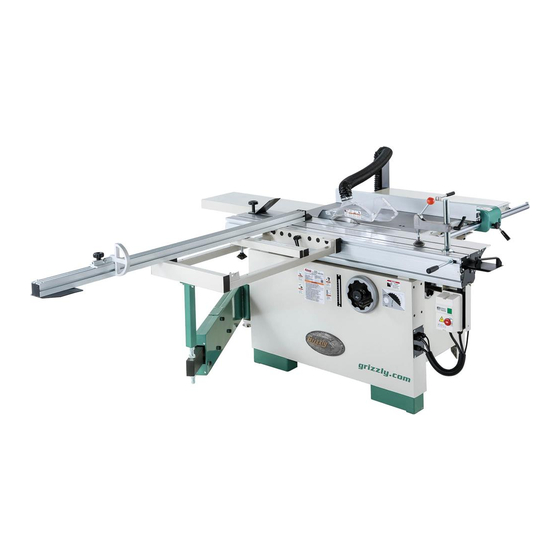
MODEL G0820
12" COMPACT SLIDING TABLE SAW
OWNER'S MANUAL
(For models manufactured since 12/16)
COPYRIGHT © FEBRUARY, 2017 BY GRIZZLY INDUSTRIAL, INC.
WARNING: NO PORTION OF THIS MANUAL MAY BE REPRODUCED IN ANY SHAPE
OR FORM WITHOUT THE WRITTEN APPROVAL OF GRIZZLY INDUSTRIAL, INC.
#BL18666 PRINTED IN TAIWAN
V1.02.17
Advertisement
Table of Contents

Related Manuals for Grizzly G0820


Summary of Contents for Grizzly G0820
- Page 1 (For models manufactured since 12/16) COPYRIGHT © FEBRUARY, 2017 BY GRIZZLY INDUSTRIAL, INC. WARNING: NO PORTION OF THIS MANUAL MAY BE REPRODUCED IN ANY SHAPE OR FORM WITHOUT THE WRITTEN APPROVAL OF GRIZZLY INDUSTRIAL, INC. #BL18666 PRINTED IN TAIWAN V1.02.17...
- Page 2 This manual provides critical safety instructions on the proper setup, operation, maintenance, and service of this machine/tool. Save this document, refer to it often, and use it to instruct other operators. Failure to read, understand and follow the instructions in this manual may result in fire or serious personal injury—including amputation, electrocution, or death.
-
Page 3: Table Of Contents
Push Blocks ..........65 Glossary Of Terms ......... 6 SECTION 6: AFTERMARKET Sliding Table Saw Capacities ......7 ACCESSORIES FROM GRIZZLY ....66 Machine Data Sheet ........8 SECTION 7: MAINTENANCE ......68 SECTION 1: SAFETY ........10 Schedule ............68 Safety Instructions for Machinery .... -
Page 4: Introduction
ID label (see below). This information is required for us to provide proper tech support, and it helps us determine if updated documenta- tion is available for your machine. Manufacture Date Serial Number Model G0820 (Mfd. Since 12/16) -
Page 5: Identification
E. Blade Guard. Fully enclosed, adjustable platform for supporting full-size panels during blade guard maintains maximum protection crosscutting operations. around saw blade with a 2 ⁄ " dust port that effectively extracts dust from cutting operation. Model G0820 (Mfd. Since 12/16) -
Page 6: Controls & Components
B. Slide Lock Handle. Secures aluminum fence face on its forward/backward slide track. C. Micro-Adjust Knob. Provides precise adjust- ment of fence. Tighten micro-adjust lock knob to use this feature. Model G0820 (Mfd. Since 12/16) -
Page 7: Front Controls
T-handle wrench. R. Scoring Blade Alignment Bolt. Adjusts the alignment of scoring blade to the main blade using the T-handle wrench. Model G0820 (Mfd. Since 12/16) -
Page 8: Glossary Of Terms
The following is a list of common definitions, terms and phrases used throughout this manual as they relate to this sliding table saw and woodworking in general. Become familiar with these terms for assembling, adjusting or operating this machine. Your safety is VERY important to us at Grizzly! Arbor: Metal shaft extending from the drive Non-Through Cut: A sawing operation in which mechanism, to which saw blade is mounted. -
Page 9: Sliding Table Saw Capacities
SLIDING TABLE SAW CAPACITIES Customer Service #: (570) 546-9663 • To Order Call: (800) 523-4777 • Fax #: (800) 438-5901 MODEL G0820 12" COMPACT SLIDING TABLE SAW Max Workpiece Length 33" " 47" 63" " Miter Cut 45º (push cut) Crosscut "... -
Page 10: Machine Data Sheet
MACHINE DATA SHEET Customer Service #: (570) 546-9663 · To Order Call: (800) 523-4777 · Fax #: (800) 438-5901 MODEL G0820 12" COMPACT SLIDING TABLE SAW Product Dimensions: Weight................................828 lbs. Width (side-to-side) x Depth (front-to-back) x Height................. 115 x 90 x 45 in. - Page 11 The information contained herein is deemed accurate as of 2/28/2017 and represents our most recent product specifications. Model G0820 PAGE 2 OF 3 Due to our ongoing improvement efforts, this information may not accurately describe items previously purchased. Model G0820 (Mfd. Since 12/16)
-
Page 12: Section 1: Safety
Everyday ery. Never operate under the influence of drugs or eyeglasses are NOT approved safety glasses. alcohol, when tired, or when distracted. -10- Model G0820 (Mfd. Since 12/16) - Page 13 EXPERIENCING DIFFICULTIES. If at any time debris. Make sure they are properly installed, you experience difficulties performing the intend- undamaged, and working correctly BEFORE ed operation, stop using the machine! Contact our operating machine. Technical Support at (570) 546-9663. -11- Model G0820 (Mfd. Since 12/16)
-
Page 14: Additional Safety For Sliding Table Saws
Feed cuts all the way through to completion. Never perform any operation “freehand”. Turn OFF saw and wait until blade is completely stopped before removing workpiece. -12- Model G0820 (Mfd. Since 12/16) -
Page 15: Preventing Kickback
In addition to the danger of the operator or others in the area being struck by the flying stock, it is often the case that the operator’s hands are pulled into the blade during the kickback. -13- Model G0820 (Mfd. Since 12/16) -
Page 16: Section 2: Power Supply
-14- Model G0820 (Mfd. Since 12/16) -
Page 17: Grounding Instructions
If you must use a phase converter, Ground Ground only use a rotary phase converter that is sized at least 50% larger than largest HP Figure 7. Typical hardwire setup with a locking rating of this machine. disconnect switch. -15- Model G0820 (Mfd. Since 12/16) -
Page 18: 440V Conversion
440V Conversion Remove fuse from “220V” holder and insert it into “440V” holder (see illustration in Figure 9). The Model G0820 can be converted from 440V Fuse 220V Fuse 220V to 440V operation using the optional part Holder Holder #P08200084. This can be purchased from the Grizzly Order desk at (800) 523-4777. -
Page 19: Section 3: Setup
IMPORTANT: Save all packaging materials until you are completely satisfied with the machine and have resolved any issues between Grizzly or the shipping agent. You MUST have the original pack- aging to file a freight claim. It is also extremely helpful if you need to return your machine later. -
Page 20: Hardware Recognition Chart
Hardware Recognition Chart USE THIS CHART TO MATCH UP HARDWARE DURING THE INVENTORY AND ASSEMBLY PROCESS. Flat Head Screw -18- Model G0820 (Mfd. Since 12/16) -
Page 21: Inventory
C. Crosscut Table ........... 1 D. Rip Fence Rail w/Fasteners ....... 1 E. Crosscut Fence Assembly ......1 Rip Fence ........... 1 G. Rip Fence Scale ......... 1 Figure 11. G0820 Inventory 1. Figure 12. G0820 Inventory 2. -19- Model G0820 (Mfd. Since 12/16) - Page 22 Lock Nut M10-1.5 (Blade Guard) ....... 1 Cap Screw M10-1.5 x 20 (Dust Hose) ....1 Flat Washer 10mm (Dust Hose) ......1 Lock Nut M10-1.5 (Dust Hose) ......1 Figure 13. G0820 Inventory 3. -20- Model G0820 (Mfd. Since 12/16)
-
Page 23: Cleanup
Figure 14. T23692 Orange Power Degreaser. Repeat Steps 2–3 as necessary until clean, then coat all unpainted surfaces with a quality metal protectant to prevent rust. -21- Model G0820 (Mfd. Since 12/16) -
Page 24: Site Considerations
Only install in an Shadows, glare, or strobe effects that may distract access restricted location. or impede the operator must be eliminated. 150" 115" " " 59" Figure 15. Minimum working clearances. -22- Model G0820 (Mfd. Since 12/16) -
Page 25: Lifting & Placing
Remove small items packed around saw and unbolt saw from pallet. Tighten hex nuts against frame to prevent hex bolts from moving after leveling. Harwired machines must be secured to the floor. -23- Model G0820 (Mfd. Since 12/16) -
Page 26: Assembly
(see Figure 19). tioned in front of T-slot, as shown in Figure 21. End Cover T-Slot End Cap Push Handle Figure 19. End cap attached to sliding table. Figure 21. End cover and push handle installed. -24- Model G0820 (Mfd. Since 12/16) - Page 27 — If both tables are not parallel with straight- edge, loosen hex nuts on set screws shown in Figure 24. Adjust set screws to align top of small extension table with top of cast-iron table, then retighten hex nuts to secure setting. -25- Model G0820 (Mfd. Since 12/16)
- Page 28 Knob in Figure 26. Bolt Lock Rail Studs Handles Figure 28. Rip fence attached with lock handles and lock knob installed. Figure 26. Removing rip fence rail hardware to prepare for installation. -26- Model G0820 (Mfd. Since 12/16)
- Page 29 Flange Arbor Nut Figure 30. Location of magnetic catches that secure blade cover. The Model G0820 does not ship with a 12" Figure 32. Flange and arbor nut removed from main blade. Refer to Blade Requirements arbor. and Blade Selection beginning on Page 44 when purchasing the main blade.
- Page 30 Main Blade Flange Figure 36. Adjusting splitter/riving knife-to-blade spacing. Arbor Nut Figure 34. Main blade installed on arbor. 27. Close blade cover, then move sliding table all the way back and remove T-handle wrench. -28- Model G0820 (Mfd. Since 12/16)
- Page 31 35. Adjust rip fence to main blade and tables, as instructed in Calibrating Rip Fence on Sliding Table Page 79. Lock Lever Figure 38. Location of sliding table lock lever. 32. Position rip fence ⁄ " away from main blade. -29- Model G0820 (Mfd. Since 12/16)
- Page 32 Threaded Hole 0° Stop Block T-Slot Alignment Plates Figure 42. Attaching crosscut table to machine Stop frame. Bolt Hole Figure 45. 90° stop block installed. -30- Model G0820 (Mfd. Since 12/16)
- Page 33 (see Figure 48). This will be used to attach flip stop in Step 51. T-Nut T-Slot Long Knob Figure 50. Long knob installed under middle of crosscut fence. Figure 48. T-nut installed on right end of crosscut table T-slot. -31- Model G0820 (Mfd. Since 12/16)
- Page 34 10mm flat washer, and (1) M10-1.5 lock nut (see Figure 54). Figure 52. Flip stop installed onto crosscut fence. Note: The support can be placed on either the rear or side of the extension table using the two available holes. -32- Model G0820 (Mfd. Since 12/16)
-
Page 35: Dust Collection
" dust hose to blade guard with hose clamp, as shown in Figure 56. Hose Clamp DO NOT operate the Model G0820 without an adequate dust collection system. This saw creates substantial amounts of wood dust while operating. Failure to use a dust collec- tion system can result in short and long-term respiratory illness. -
Page 36: Power Connection
NOTICE Ground Incoming Power The Model G0820 is prewired for 220V. If Terminal Terminals you plan to operate the machine at 440V, refer to 440V Conversion on Page 16 for Figure 60. -
Page 37: Test Run
POWER! Phase of incoming power sup- ply is reversed. Remove power connection junction box cover and swap wires at “R” and “T" terminals (see Figure 62), then re-install junction box cover and reconnect machine to power. -35- Model G0820 (Mfd. Since 12/16) - Page 38 Call Tech Support for help. Reset Emergency Stop button on front of machine. 13. Carefully close blade cover, then move slid- ing table back to center of machine. -36- Model G0820 (Mfd. Since 12/16)
-
Page 39: Recommended Adjustments
This safety feature must work prop- erly before proceeding with regular opera- tions. Call Tech Support for help. 16. Close cabinet door, then push Emergency Stop button. Congratulations. Test Run is complete! -37- Model G0820 (Mfd. Since 12/16) -
Page 40: Section 4: Operations
Read books/magazines or get formal training before beginning any proj- ects. Regardless of the content in this sec- tion, Grizzly Industrial will not be held liable for accidents caused by lack of training. -38- Model G0820 (Mfd. Since 12/16) -
Page 41: Workpiece Inspection
Minor Warping: Slightly cupped workpieces can be safely supported with cupped side facing the table or fence; however, work- pieces supported on the bowed side will rock during the cut, which could cause kickback. -39- Model G0820 (Mfd. Since 12/16) -
Page 42: Blade Guard & Splitter/Riving Knife
(Reaching behind the blade is a Figure 69. Blade guard mounted to splitter/riving major safety risk and should not be done). knife. -40- Model G0820 (Mfd. Since 12/16) - Page 43 Minimum 3mm Maximum 8mm f) Do not perform any operation freehand. g) Never reach around or over saw blade. Figure 71. Allowable top and bottom distances between splitter/riving knife and blade. -41- Model G0820 (Mfd. Since 12/16)
-
Page 44: Riving Knife
Riving Knife Mounting Block on Page 78. Top Distance Minimum 3mm Maximum 8mm Bottom Distance Minimum 3mm Maximum 8mm Figure 75. Allowable top and bottom distances between riving knife and blade. -42- Model G0820 (Mfd. Since 12/16) - Page 45 Page 78. risk reduction than the riving knife. Therefore, we strongly recommend that you use the blade guard assembly and splitter/riving knife instead of the riving knife for through-cuts. -43- Model G0820 (Mfd. Since 12/16)
-
Page 46: Blade Requirements
(similar • 30-40 teeth to a ripping blade • Flat-top ground tooth profile • Large gullets for large chip removal Alternate Flat Bevel Blade Flat Figure 81. Combination blade. Figure 79. Ripping blade. -44- Model G0820 (Mfd. Since 12/16) -
Page 47: Changing Main Blade
Triple Chip The Model G0820 does not ship with a 12" Blade main blade. Refer to Blade Requirements and Blade Selection beginning on Page 44 when purchasing the main blade. -
Page 48: Replacing & Aligning Scoring Blade
(see Figure 84). The scoring blade included with the Model G0820 has wedge-shaped teeth that narrow at the top, Flange as shown in Figure 86. With this style of scoring... - Page 49 (left-hand threads), and remove arbor hex bolt, flange, and blade (see Figure 88). Flange Hex Bolt Arbor Wrench Scoring Blade 19mm Wrench Figure 88. Scoring blade, flange, arbor hex bolt, 19mm wrench, and arbor wrench. -47- Model G0820 (Mfd. Since 12/16)
- Page 50 Close blade cover, properly reposition blade guard, and slide table back to center of machine. Perform a test cut and check for chip-out. If there is chip-out, repeat this procedure until corrected. -48- Model G0820 (Mfd. Since 12/16)
-
Page 51: Setting Up Crosscut Fence
0° stop bolts are properly adjusted before using the fence. Refer to Squaring Crosscut Fence to Blade on Page 77 for further details. Figure 95. Stop block against 0° stop bolt. -49- Model G0820 (Mfd. Since 12/16) - Page 52 Figure 98. Location of sliding table lock lever. then re-insert pivot bolt into hole. Repeat measurement in Step 3. — If measurement is not exactly 3", repeat Step 4 until it is. Re-install knob bolts removed earlier to secure setting. -50- Model G0820 (Mfd. Since 12/16)
-
Page 53: Rip Cutting
Rip Cutting Loosen crosscut table lock lever shown in Figure 99. The Model G0820 has the capability of rip cutting large panels (see Figure 100). The sliding table removes the burden of sliding a large and heavy panel over a stationary table surface. - Page 54 Knob Bolt Figure 105. Location of sliding table lock lever. Flip Stop Figure 103. Location of flip stop and flip stop knob bolt. -52- Model G0820 (Mfd. Since 12/16)
- Page 55 Horizontal Load workpiece onto table saw. The setup should look similar to Figure 101 on Page 51. 10. Take all necessary safety precautions, then Figure 107. Rip fence positions. perform cutting operation. -53- Model G0820 (Mfd. Since 12/16)
-
Page 56: Crosscutting
Figure 111. The Model G0820 can crosscut full-size pan- els with the fence in the front or rear position, although it is easier to load full-size panels with the crosscut fence mounted in the front position (see Figure 109). - Page 57 Load workpiece onto table saw in rear mount- ing location, shown in Figure 110. If neces- sary, use edge shoe to secure workpiece to sliding table. Take all necessary safety precautions, then perform cutting operation. -55- Model G0820 (Mfd. Since 12/16)
-
Page 58: Miter Cutting
Figures 115–116. Rear Hole Figure 115. Crosscut fence mounted in rear hole Take all necessary safety precautions, con- for miter cuts from 0° to 45°. nect saw to power, then perform cutting operation. -56- Model G0820 (Mfd. Since 12/16) -
Page 59: Dado Cutting
Blade Cut 2 dedicated dado blade or a standard saw blade. Fence However, since the Model G0820 cannot accept Workpiece dado blades, a standard blade must be used. To use standard saw blade to cut a dado: Figure 119. Second cut for a single-blade dado. -
Page 60: Rabbet Cutting
Typically, rabbets can be cut with either a dado on table. blade or a standard saw blade. However, because the Model G0820 cannot accept dado blades, rab- bets must be cut with a standard saw blade only. Always use push sticks, featherboards,... -
Page 61: Resawing
IMPORTANT: This table saw can only resaw ⁄ " Wood Screw wood that is less than 8" tall, and the rip fence must be used (rather than the sliding table). ⁄ " Assembled Resaw Barrier Figure 123. Resaw barrier. -59- Model G0820 (Mfd. Since 12/16) - Page 62 (see 12. When finished resawing, remove resaw bar- Figure 124). rier and reposition blade guard over blade. Workpiece Fence Resaw Barrier " Connection Figure 124. Ideal completed resaw cut. -60- Model G0820 (Mfd. Since 12/16)
-
Page 63: Section 5: Shop Made Safety Accessories
Step 3 will bend without breaking. Cut a 30º angle at one end of board. NOTICE Only Steps 1–3 are required to make a clamp-mounted featherboard. Refer to Page 63 for instructions on clamping. -61- Model G0820 (Mfd. Since 12/16) - Page 64 Figure 127. Miter bar pattern. Now, proceed to Mounting Featherboard in Miter Slot on Page 63. Drill ⁄ " hole in center of bar, then countersink bottom to fit ⁄ "-20 flat head screw. -62- Model G0820 (Mfd. Since 12/16)
- Page 65 Note: The featherboard should be placed firmly enough against the workpiece to keep it against the fence but not so tight that it is difficult to feed the workpiece. -63- Model G0820 (Mfd. Since 12/16)
-
Page 66: Push Sticks
⁄ " Grid increase comfort. from the blade! Figure 133. Template for a basic shop-made push stick (not shown at actual size). -64- Model G0820 (Mfd. Since 12/16) -
Page 67: Push Blocks
Lip for pushing workpiece ⁄ " Grid 9"−10" Minimum Length Figure 136. Template for a shop-made push block (shown at 50% of full size). -65- Model G0820 (Mfd. Since 12/16) -
Page 68: Section 6: Aftermarket Accessories From Grizzly
For thin veneers on flakeboard - fire- To reduce this risk, only install accessories retardant, laminated (1 or 2 sides), masonite, fiber recommended for this machine by Grizzly. board, lumbercore, glue-ups, hard/soft woods and chemically impregnated wood. Arbor bore size is NOTICE 1"... - Page 69 Figure 143. G0777 Ultra-Quiet Cyclone • Maximum weight capacity: 300 lbs. Dust Collector. Multiple stands can be connected for unlimited rolling capacity Figure 142. W1732 Adjustable Roller Stand. www.grizzly.com 1-800-523-4777 order online at or call -67- Model G0820 (Mfd. Since 12/16)
-
Page 70: Section 7: Maintenance
To reduce risk of shock or accidental startup, always disconnect machine from power before adjustments, Cleaning the Model G0820 is relatively easy. maintenance, or service. Vacuum excess wood chips and sawdust, and wipe off the remaining dust with a dry cloth. If any... -
Page 71: Lubrication
Grease Gun ............1 Mineral Spirits ........As Needed Clean Shop Rags ......As Needed Light Machine Oil....... As Needed Blade Height Trunnion (Grease Behind Plate) Figure 145. Trunnion lubrication locations (table removed for clarity). -69- Model G0820 (Mfd. Since 12/16) - Page 72 Move the sliding table through its full range of movement several times to evenly distribute the oil. Elevation Leadscrew Tilt Leadscrew (1 of 2) Figure 146. Elevation leadscrew locations. (1 of 2) Figure 147. Sliding table way (1 of 2). -70- Model G0820 (Mfd. Since 12/16)
-
Page 73: Section 8: Service
7. Clean motor, let cool, and reduce workload. 8. Dull blades. 8. Sharpen/replace blades. 9. Pulley slipping on shaft. 9. Replace loose pulley/key/set screw. 10. Magnetic switch contactor at fault (not 10. Test all legs for power/replace. energized/has poor contacts). -71- Model G0820 (Mfd. Since 12/16) -
Page 74: Machine Operation
1. Loosen lock knob. height 2. Leadscrews caked with dust. 2. Clean off dust and lubricate leadscrews/gears. handwheels 3. Stop nuts hitting end of tilt leadscrew travel. 3. Turn handwheel in opposite direction. difficult to turn. -72- Model G0820 (Mfd. Since 12/16) -
Page 75: Belt Service
Step 3. Pulley Scoring Blade ⁄ " Belt Deflection Spring Pulley Figure 148. Location of scoring blade spring. Figure 150. Testing for the correct amount of belt tension. Close motor cabinet door. -73- Model G0820 (Mfd. Since 12/16) - Page 76 Belt on Page 73). Raise motor to top position, then tighten bolts Tighten pivot bolt and two adjustment bolts. loosened in Step 3. Close motor cabinet door. Remove scoring belt, then remove main belt from pulleys. -74- Model G0820 (Mfd. Since 12/16)
-
Page 77: Blade Tilt Calibration
Figure 155. These are Figure 153. Blade tilt stop nuts. accessed inside the cabinet. Tilt Scale Cable Hex Nuts Figure 155. Tilt scale cable hex nuts. -75- Model G0820 (Mfd. Since 12/16) -
Page 78: Sliding Table Parallel Adjustment
Figure 156. Measuring distance between miter Once sliding table parallelism is within 0.004" slot and blade at each end of sliding table. from one end to the other, retighten hex nuts. -76- Model G0820 (Mfd. Since 12/16) -
Page 79: Squaring Crosscut Fence To Blade
(see Figure 160), then retighten angle scale knob bolt to secure fence in place. 0° Stop 0° Stop Block Bolt Figure 162. Diagonals to measure on test piece. Figure 160. Stop block against 0° stop bolt. -77- Model G0820 (Mfd. Since 12/16) -
Page 80: Riving Knife Mounting Block
Tools Needed Straightedge ............1 Open-End Wrench 17mm ........1 Hex Wrench 2.5mm ........... 1 -78- Model G0820 (Mfd. Since 12/16) -
Page 81: Calibrating Rip Fence
Properly re-install riving knife as described on Acorn Nut Page 43, close blade cover, and move sliding table back to center position. Figure 165. Rip fence base roller controls. -79- Model G0820 (Mfd. Since 12/16) - Page 82 Re-install blade guard cover. Figure 166. Rip fence scale zero mark. Re-install blade guard cover. -80- Model G0820 (Mfd. Since 12/16)
-
Page 83: Section 9: Wiring
Technical Support at (570) 546-9663. The photos and diagrams included in this section are best viewed in color. You can view these pages in color at www.grizzly.com. -81- Model G0820 (Mfd. Since 12/16) -
Page 84: Wiring Diagram 220V
RENY R9C01 AC15-DC13 10A 600V MAGNETIC SWITCH ASSEMBLY SDE MP-18E 220V/440V In-Line Motor Temperature Connection Ground = For phase converter wild wire (if used) To L15-30 Plug (as recommended) Ground READ ELECTRICAL SAFETY -82- Model G0820 (Mfd. Since 12/16) ON PAGE 81! -
Page 85: Wiring Diagram 440V
220V to 440V. In-Line Motor Temperature Connection Ground = For phase converter wild wire (if used) 440V Conversion 3-PHASE 440 VAC Ground DISCONNECT SWITCH (as recommended) READ ELECTRICAL SAFETY -83- Model G0820 (Mfd. Since 12/16) ON PAGE 81! -
Page 86: Wiring Photos
Figure 171. Blade guard limit switch wiring. Fuse FSB102 600V 2A Contactor SDE MA-18 OL Relay RA-30E 11–22A Figure 169. Magnetic switch wiring (220V). Figure 172. Cabinet E-stop button wiring. READ ELECTRICAL SAFETY -84- Model G0820 (Mfd. Since 12/16) ON PAGE 81! -
Page 87: Section 10: Parts
SECTION 10: PARTS We do our best to stock replacement parts when possible, but we cannot guarantee that all parts shown are available for purchase. Call (800) 523-4777 or visit www.grizzly.com/parts to check for availability. Body 56-1 56-7 56-2 56-8... - Page 88 FLAT WASHER 10MM P08200085 E-STOP CORD 18AWG 2W X 96" P08200054 LOCK WASHER 10MM P08200086 POWER CORD 12AWG 4W X 96" P08200055 CAP SCREW M10-1.5 X 35 P08200087 HINGE RECEIVER P08200056 TILT INDICATOR ASSEMBLY -86- Model G0820 (Mfd. Since 12/16)
-
Page 89: Main Tables
SET SCREW M16-2 X 100 P08200125 HEX NUT M12-1.75 P08200112 LOCK NUT M16-2 P08200126 RIP FENCE SCALE PLATE P08200113 FLAT WASHER 16MM P08200127 HEX NUT M6-1 P08200114 HEX NUT M16-2 P08200128 RIP FENCE SCALE -87- Model G0820 (Mfd. Since 12/16) -
Page 90: Blade Enclosure
CAP SCREW M5-.8 X 8 P08200248 STUD-SE M20-2.5 X 415 P08200228 COVER SUPPORT BRACKET P08200249 PIVOT COUPLER P08200229 FLAT WASHER 5MM P08200250 SET SCREW M6-1 X 6 P08200230 LOCK WASHER 5MM P08200251 SET NUT M20-2.5 -88- Model G0820 (Mfd. Since 12/16) -
Page 91: Main Motor
CAP SCREW M6-1 X 16 P08200319 EXT RETAINING RING 28MM P08200337 LOWER TENSIONER PLATE P08200321 HEX NUT M12-1.75 P08200338 E-STOP CORD 18AWG 2W X 72" P08200322 PULLEY BEARING SHAFT P08200339 MOTOR CORD 12AWG 4W X 108" -89- Model G0820 (Mfd. Since 12/16) -
Page 92: Main Blade Arbor & Dust Hood
HOSE SUPPORT PLATE 417-1 P08200417-1 HEX NUT M10-1.5 P08200508 FLAT WASHER 10MM 417-2 P08200417-2 FENDER WASHER 10MM P08200509 HEX NUT M10-1.5 417-3 P08200417-3 RIVING KNIFE MOUNTING BLOCK P08200510 SPLITTER/RIVING KNIFE 417-4 P08200417-4 MOUNTING PLATE -90- Model G0820 (Mfd. Since 12/16) -
Page 93: Scoring Blade Arbor & Handwheel
SET SCREW M10-1.5 X 35 P08200606 FLAT WASHER 6MM P08200723 HEX NUT M10-1.5 P08200607 LOCK WASHER 6MM P08200724 SET SCREW M6-1 X 8 P08200608 CAP SCREW M6-1 X 16 P08200725 SELF-LUBRICATING BEARING 16 X 10MM -91- Model G0820 (Mfd. Since 12/16) -
Page 94: Crosscut Table
813-1 P08200813-1 FRAME END-CAP 38 X 38MM P08200816 CAP SCREW M6-1 X 16 813-2 P08200813-2 FRAME END-CAP 40 X 20MM P08200817 SUPPORT LEG 813-3 P08200813-3 BUTTON HD CAP SCR M6-1 X 16 P08200818 END PLUG -92- Model G0820 (Mfd. Since 12/16) -
Page 95: Crosscut Fence
SET SCREW M5-.8 X 5 P08200907 ROTATE SHAFT 902-2 P08200902-2 SQUARE NUT M5-.8 (THIN) P08200908 FLAT WASHER 10MM NYLON 902-3 P08200902-3 EXTENSION FENCE END CAP P08200909 SQUARE NUT M8-1.25 902-4 P08200902-4 TAP SCREW M4-.7 X 10 -93- Model G0820 (Mfd. Since 12/16) -
Page 96: Crosscut Swing-Arm
1025 P08201025 SET SCREW PROTECTIVE CAP 13MM 1016 P08201016 BALL BEARING 6004ZZ 1026 P08201026 BUTTON HD CAP SCR M5-.8 X 8 1017 P08201017 BRUSH 1027 P08201027 SWING-ARM TOP PLATE 1018 P08201018 FLAT WASHER 6MM -94- Model G0820 (Mfd. Since 12/16) -
Page 97: Rip Fence
P08201103 KNOB BOLT M10-1.5 X 55 1101-15 P08201101-15 LOCK WASHER 8MM 1104 P08201104 LEVER HANDLE M10-1.5 X 12, 140L 1101-16 P08201101-16 BALL BEARING 6202ZZ 1105 P08201105 FENCE 36" (ALUMINUM) 1101-17 P08201101-17 ACORN NUT M8-1.25 -95- Model G0820 (Mfd. Since 12/16) -
Page 98: Sliding Table
1235 P08201235 END CAP BRACKET 1217 P08201217 COVER STRIP 1236 P08201236 LOCK WASHER 6MM 1218 P08201218 ADHESIVE STRIP 1237 P08201237 BUTTON HD CAP SCR M6-1 X 12 1219 P08201219 CAP SCREW M8-1.25 X 16 -96- Model G0820 (Mfd. Since 12/16) -
Page 99: Sliding Table Accessories
1306-3 P08201306-3 FLAT WASHER 10MM 1305-6 P08201305-6 COMPRESSION SPRING 40 X 18 X 1.6MM 1306-4 P08201306-4 KNOB M10-1.5 1305-7 P08201305-7 FLUTED PIVOT PIN 1306-5 P08201306-5 T-SLOT BOLT M10-1.5 X 25 1305-8 P08201305-8 HOLD-DOWN BRACKET -97- Model G0820 (Mfd. Since 12/16) -
Page 100: Labels & Cosmetics
POWER BEFORE included with this machine. Always wear safety DO NOT stand machine. WITHOUT WRITTEN APPROVAL! Grizzly will not accept labels changed without approval. WARNING! Always wear safety WARNING! ADJUSTMENTS, machine. ADJUSTMENTS, Refer to the owner’s Failure to follow these instructions... -
Page 101: Warranty Card
Would you recommend Grizzly Industrial to a friend? _____ Yes _____No Would you allow us to use your name as a reference for Grizzly customers in your area? Note: We never use names more than 3 times. _____ Yes _____No 10. - Page 102 FOLD ALONG DOTTED LINE Place Stamp Here GRIZZLY INDUSTRIAL, INC. P.O. BOX 2069 BELLINGHAM, WA 98227-2069 FOLD ALONG DOTTED LINE Send a Grizzly Catalog to a friend: Name_______________________________ Street_______________________________ City______________State______Zip______ TAPE ALONG EDGES--PLEASE DO NOT STAPLE...
-
Page 103: Warranty & Returns
WARRANTY & RETURNS Grizzly Industrial, Inc. warrants every product it sells for a period of 1 year to the original purchaser from the date of purchase. This warranty does not apply to defects due directly or indirectly to misuse, abuse, negligence, accidents, repairs or alterations or lack of maintenance.