Table of Contents
Advertisement
Instruction Manual
Form 1013
February 1997
2500 and 2503 Series Level-Trol Controllers and
Transmitters
Contents
. . . . . . . . . . . . . . . . . . . . . . . . . . . . . . .
. . . . . . . . . . . . . . . . . . . . . . . . . . . . .
. . . . . . . . . . . . . . . . . . . . . . . . . . . . . . . . . .
. . . . . . . . . . . . . . . . . . . . . . . . . . . . . . .
. . . . . . . . . . . . . . . . . . . . . . . . . . . . . . . . . .
. . . . . . . . . . . . . . . . . . . . . . . . . . . .
. . . . . . . . . . . . . . . . . . . . . . . . . . . . . . . . . . .
. . . . . . . . . . . . . . . . . . . . . . . . . .
. . . . . . . . . . . . . . . . . . . . . . . . . . . .
. . . . . . . . . . . . . . . . . . . . . . . . . .
Type 2500 Controller or Type 2500T
. . . . . . . . . . . . . . . . . . . . . . . . . . . . .
. . . . . . . . . . . . . . . . . . . . . . .
. . . . . . . . . . . . . . . . . . . . . . . . . . . . . . .
. . . . . . . . . . . . . . . . . . . . . . . . . . . .
. . . . . . . . . . . . . . . . . . . . . . . . . . . . . . . . .
. . . . . . . . . . . . . . . . . . . . . . . . . . .
. . . . . . . . . . . . . . . . . . . . . . . . . . .
Fisher, Fisher-Rosemount, and Managing The Process Better are marks
owned by Fisher Controls International, Inc. or Fisher-Rosemount Systems, Inc.
All other marks are the property of their respective owners.
Fisher Controls International, Inc. 1977, 1997; All Rights Reserved
. . . . . . . . . . . . . .
. . . . . . . . . . . . . . . . . . . . . .
. . . . . . . . . . . . . . . . . . . .
. . . . . . . . . . . . . . . . . . . . . . .
. . . . . . . . . . . . . . . . . . . . . . . .
. . . . . . . . .
. . . . . . . .
. . . .
. . . . . . . . . . . . . . . . . . . . . .
11
. . . . . . . . . . . . . . . . . . . . . .
. . . . . . . . . . . . . . . . . . . . . .
. . . . . . . . . . . . . . . . . . . . .
. . . . . . . . . . . . . . . . . . . . . .
. . . . . . . . . . . . . . . . . . . . . .
. . . . . . . . . . . . . . . . .
2
2
2
2
2
2
2
6
6
7
7
8
8
8
9
9
10
11
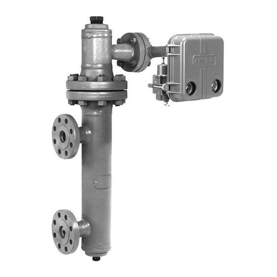
W3121-3/IL/A
Figure 1. 2500 or 2503 Series Level-Trol Controller/
Transmitter on Caged 249 Series Sensor
13
13
14
15
15
15
15
15
15
. . . . . . . . . . . . . . . . . . . . . . . . . . . . . . . . . . . . . .
15
15
15
16
Type 2500
2500 OR 2503 SERIES
CONTROLLER/
TRANSMITTER
249 SERIES SENSOR
. . . . . . . . . . . . . . . . . . . . . . . . . . .
. . . . . . . . . . . . . . . . . . . . .
. . . . . . . . . . . . . . . . . . . . . .
. . . . . . . . . . . . . . . . . . . . . .
. . . . . . . . . . .
. . . . . . . . . . . . . . . . . . . . . . .
. . . . . . . . . . . . . . . . . . . .
. . . . . . . . . . . . . . . . . . . . . .
. . . . . . . . . . . . . . . . . . . . . . .
16
16
17
17
19
20
20
20
20
20
Advertisement
Table of Contents

Related Manuals for Fisher 2500 Series


![Controller Fisher] 3660 Instruction Manual](https://static-data2.manualslib.com/product-images/3ac/1225055/60x60/fisher-3660-controller.jpg)


Summary of Contents for Fisher 2500 Series
-
Page 1: Table Of Contents
..... . . Fisher, Fisher-Rosemount, and Managing The Process Better are marks owned by Fisher Controls International, Inc. or Fisher-Rosemount Systems, Inc. All other marks are the property of their respective owners. -
Page 2: Introduction
Uncrating maintain these controller/transmitters. If you have any questions concerning these instructions, contact your Unless ordered separately, the controller/transmitter is Fisher Controls sales office or sales representative attached to the sensor when shipped. Carefully un- before proceeding. crate the assembly. - Page 3 Steady-State Air Consumption figure 2. Relay temperature limits are: 2500 Series Controllers and Transmitters (2500, Standard Construction: -40 to 160 F (-40 to 2500C, 2500R, 2500S, and 2500T): See Table 3. 71 C)
- Page 4 42 scfh 45 psig (3 bar) 1. Consult your Fisher Controls representative about gauges in other units. 2. Control and stability may be impaired if this pressure is exceeded. 3. At zero or maximum proportional band or specific gravity setting.
- Page 5 Type 2500 AMBIENT TEMPERATURE ( C) AMBIENT TEMPERATURE ( C) –18 –10 –10 –18 1100 1100 HEAT INSULATOR HEAT INSULATOR REQUIRED REQUIRED –18 NO INSULATOR NECESSARY NO INSULATOR NECESSARY –29 –20 USE INSULATOR (CAUTION! IF AMBIENT DEWPOINT IS ABOVE PROCESS –40 –40 USE INSULATOR (CAUTION! IF AMBIENT DEWPOINT IS ABOVE...
-
Page 6: Controller/Transmitter Orientation
Type 2500 tion changes the control action from direct to reverse, or vice versa. All caged sensors have a rotatable head. That is, the controller/transmitter may be positioned at any of eight alternate positions around the cage as indicated by the numbers 1 through 8 in figure 4. -
Page 7: Mounting Cageless Sensor
Type 2500 Mounting Cageless Sensor CAUTION If a stillwell is used, install it plumb so that the displacer does not touch the wall of the stillwell. If the displacer touches the wall, the unit will transmit an erroneous output signal. Since the displacer hangs inside the vessel, provide a stillwell around the displacer if the fluid is in a state of continuous agitation to avoid excessive turbulence... -
Page 8: Top-Mounted Sensor
Type 2500 MOUNTED SIDE MOUNTED CF5380-A A3893/IL W0645–1/IL Figure 7. Cageless Sensor Mounting If an extension is used between the displacer spud the nuts are tight at each end of the stem. Install and and the displacer stem end piece, make sure the nuts tighten suitable cap screws in the flanged connection are tight at each end of the displacer stem extension. -
Page 9: Piezometer Ring
Type 2500 DISPLACER STEM END PIECE DISPLACER ROD DISPLACER COTTER SPRING DISPLACER STEM COTTER SPRING SPUD EXTENSION LOCKING NUTS DISPLACER SPUD W0229-1A/IL W0228-1A/IL DISPLACER ROD Figure 8. Displacer and Displacer Rod Connections Piezometer Ring A piezometer ring, shown in figure 10, is used when measuring the specific gravity of a flowing fluid in a line. -
Page 10: Supply Pressure
Due to the variability in nature 1367 High Pressure Instrument Supply System. For of the problems these influences can Type 1367 system installation, adjustment. and main- have on pneumatic equipment, Fisher tenance information, see the separate instruction Controls has no technical basis to rec- manual. -
Page 11: Controller/Transmitter Output Connection
Type 2500 Controller/Transmitter Output Connection Set the PROPORTIONAL BAND control on a Type 2500 or 2500S controller, or the SPECIFIC GRAVITY As shown in figure 11, the output pressure connection control on a Type 2500T transmitter, as follows: is on the back of the controller/transmitter case. After connecting the output pressure line, turn on the supply Sensor with Both Standard Torque Tube and pressure, adjust the filter/regulator to the appropriate... - Page 12 Type 2500 W0641–1B/IL 1C9283–B/DOC LEVEL SET ARM 3–WAY VALVE LEVEL ADJUSTMENT MOUNTING SCREWS FLAPPER ALIGNMENT SCREW NOZZLE PROPORTIONAL LEVEL SET SHAFT CLAMP NUT PLUNGER BAND ADJUSTMENT W0656–1/IL W0671–1/IL RELAY FLAPPER VENT SPAN ADJUSTMENT SPECIFIC GRAVITY ADJUSTMENT ZERO ADJUSTMENT POINTER ASSEMBLY 1E8731 W0647–2B/IL W0648–1B/IL...
-
Page 13: Transmitter
Type 2500 necessary, extrapolation may be used to determine an appropriate RAISE LEVEL or ZERO ADJUSTMENT setting. Note The raise level dial does not reflect actu- al fluid level in the tank or fluid level position on the displacer. 4. The OUTPUT gauge on a 3 to 15 psig (0.2 to 1 bar) range should read 3 psig (0.2 bar) for direct or 15 psig (1 bar) for reverse action. -
Page 14: Type 2503 Controller
Type 2500 Table 4. Recommended Settings For Pre-Startup Checks RECOMMENDED RAISE LEVEL SETTING RECOMMENDED ZERO ADJUSTMENT SETTING FOR FOR TYPE 2500 CONTROLLER TYPE 2500T TRANSMITTER MOUNTING ACTION For Predetermined For Predetermined For Predetermined For Predetermined PROPORTIONAL BAND PROPORTIONAL BAND SPECIFIC GRAVITY Dial SPECIFIC GRAVITY Dial Dial Setting of 10 Dial Setting of 0... -
Page 15: Adjustments
Type 2500 Zero Adjustment (Transmitters Only) 5. Increase the process variable until the OUTPUT gauge changes to full supply pressure for direct or 0 To make a zero adjustment, open the transmitter cov- psig (0 bar) for reverse action. The process variable er, loosen the adjustment screw and rotate the adjust- should be at the desired high trip value. -
Page 16: Dry Calibration
Avoid overloading a torque tube sized for interface or density applications. To avoid personal injury from contact Consult your Fisher Controls sales of- with the process fluid, lower the vessel fice or sales representative for the maxi- level below the sensor torque tube arm,... -
Page 17: Calibration Procedure
Type 2500 Table 5. Minimum and Maximum Limits for Setting Process Variables APPLICATION MINIMUM LIMIT MAXIMUM LIMIT Liquid Level Displacer must be completely out of liquid Displacer must be completely submerged in liquid Interface Displacer must be completely submerged in lighter of two Displacer must be completely submerged in process liquids heavier of two process liquids... - Page 18 Type 2500 4. Set the process variable to the minimum value of the indicator plate screws (key 41, figure 19, detail of the input range as shown in Table 5. For constructions indicator assembly), slide the plate until the HIGH with an indicator assembly, make sure that the pointer mark is under the pointer.
-
Page 19: Type 2500S And 2503 Controllers
Type 2500 Note For Reverse Acting Controllers, move the flap- per away from the nozzle until the output pressure If you cannot calibrate the controller or switches to 0 psig, then carefully adjust the flapper transmitter, look for other problems as toward the nozzle until the output pressure switches to described in the Troubleshooting proce- full supply pressure. -
Page 20: Startup
Type 2500 Type 2500T Transmitter Note 1. Make sure that the SPECIFIC GRAVITY and Any change in the PROPORTIONAL ZERO ADJUSTMENT controls are set according to BAND adjustment in the following step the Type 2500 Controller or 2500T Transmitter portion changes the zero as well as the differen- of the pre-startup checks procedures. -
Page 21: Proportional Valve
Type 2500 The following descriptions explain how the relay action moves to counteract the pressure changes in the produces the output signal with the various controller/ nozzle, equaling the relay diaphragm pressure differ- transmitter constructions. ential. The relay valve maintains a new output pres- sure according to the change in the process variable. -
Page 22: Maintenance
Bourdon tube valve to close, restoring loading pres- to figure 19 for key number locations, unless otherwise sure to the pneumatic circuit. Reverse-acting control- indicated. lers produce the opposite effect. Due to the care Fisher Controls takes in meeting all manufacturing requirements (heat treating, dimension-... -
Page 23: Troubleshooting
Figure 15. Direct-Acting Left-Hand-Mounted Type 2503 Controller al tolerances, etc.), use only replacement parts available. The output signal measuring device should manufactured or furnished by Fisher Controls. have corresponding accuracy. Table 6 lists some common operating faults, their probable causes, and corrective action. - Page 24 Type 2500 Table 6. Troubleshooting Chart for 2500 Series Controller/Transmitters FAULT POSSIBLE CAUSE CHECK CORRECTION 1. Process wanders or cycles 1.1 Proportional band or specific Ensure the prestartup procedures If stable control cannot be attained around set point. gravity adjustment incorrect or are completed correctly.
-
Page 25: Changing Mounting Methods
Type 2500 2. Loosen the top hex clamp nut (key 40, figure 19) and remove the flapper base (key 30, figure 19) from the torque tube rotary shaft. CAUTION If the hex clamp nut has not been loos- ened or the pointer removed according to step 2, attempting to remove the con- troller/transmitter from the sensor may bend the flapper or rotary shaft. -
Page 26: Installing Controller/Transmitter On Sensor
Type 2500 Installing Controller/Transmitter on 5. Install the flapper base (key 30, figure 19) on the torque tube rotary shaft, making sure the flapper is Sensor centered over the nozzle or Bourdon tube valve. Se- cure the base with the hex nut (key 40, figure 19). For a controller/transmitter with an indicator assembly, Note install the pointer assembly according to the section... -
Page 27: Relay Deadband Testing (Type 2500 Controller Or 2500T Transmitter Only)
Type 2500 AC9554 AR8148 BO996–1/IL Figure 17. Bourdon Tube-Flapper Arrangements for Various Actions and Mountings Relay Deadband Testing (Type 2500 ence between the two recorded values (the deadband) is more than 0.2% of the maximum displacer length, Controller or 2500T Transmitter Only) the relay must be replaced or repaired according to 1. -
Page 28: Changing Relay
Type 2500 or 90, figure 19), or the 1/8-inch NPT pipe plug (key 73, not shown), from the relay base (key 23, figure 19). 3. Install the pipe plug or the desired adjustment as- sembly into the relay base. 4. Replace the tubing (key 10) to the proportional band valve assembly. -
Page 29: Parts Ordering
1C8959 X0012 in this section. Drive-lock pin, (2 req’d) 1C8991 X0022 Tubing assembly, 12. If the deadband is within tolerance, go to the Cal- For all 2500 Series except Type 2503 ibration section. Copper 1C9154 000A2 Stainless steel 1N7983 X0012... - Page 30 Type 2500 LEVEL SET MOUNTING SCREWS SEE VIEW A 30A8865–D/DOC 32B0465–B/DOC 30A8866–C/DOC 30A8869–D/DOC NOTE: PARTS NOT SHOWN 4, 24, 38, 39, 47, AND 48. Figure 19. 2500 Series Controller / Transmitter Constructions...
- Page 31 Alignment screw, brass, pl 1B4517 14022 O-RING (KEY 90) Relay assembly ORIFICE ASSEMBLY (KEY 88) (For individual parts see following list and figure 21), For all 2500 Series except Type 2503 CORE ASSEMBLY Standard temperature 22B0463 X012 (INCLUDED WITH KEY 88)
- Page 32 *Recommended spare parts 1. Key 88, orifice assembly, now includes the core assembly. Key 89, core assembly, has been deleted from the parts list. For information, contact Fisher Controls: Marshalltown, Iowa 50158 USA Cernay 68700 France Sao Paulo 05424 Brazil Singapore 0512 Printed in U.S.A.