Table of Contents
Advertisement
Quick Links
Advertisement
Table of Contents
Troubleshooting

Related Manuals for Canon LBP351 Series


Summary of Contents for Canon LBP351 Series
-
Page 1: Service Manual
Revision 4.0 LBP351/352 Series Service Manual... -
Page 2: Explanation Of Symbols
When changes occur in applicable products or in the contents of this manual, Canon will release technical information as the need arises. In the event of major changes in the contents of this manual over a long or short period, Canon will issue a new edition of this manual. - Page 3 Introduction Symbols Explanation Symbols Explanation Disconnect the connector. Connect the power cable. Connect the connector. Disconnect the power cable. Remove the cable/wire from the Turn on the power. cable guide or wire saddle. Install the cable/wire to the cable Turn off the power. guide or wire saddle.
-
Page 4: Table Of Contents
Contents Contents Safety Precautions....................1 Laser Safety............................2 How to Handle the Laser Scanner Unit....................2 Power Supply............................2 Toner Safety............................3 About Toner............................3 Handling Adhered Toner........................3 Notes When Handling a Lithium Battery..................... 3 Notes Before it Works Serving......................3 Points to Note at Cleaning........................4 Notes on Assembly/Disassembly...................... - Page 5 Contents Energy Saving Function........................40 3. Technical Explanation (System)..............41 Version Upgrade..........................42 Overview............................42 Version Upgrade Using UST........................ 43 Update Using Updater......................... 43 Backup/Restoration........................... 72 Backup/Restoration Using the DCM Function..................72 Backup/Restoration Using a Function Other Than the DCM Function............. 80 Monitoring Function (e-Maintenance/imageWARE Remote)............
- Page 6 Contents Removing the DC Controller PCB.......................125 Removing the AC Relay PCB......................126 Removing the Power Supply PCB...................... 126 Removing the All-Night Power Supply PCB..................129 Removing the Sleep Interface PCB.....................129 Laser Exposure System........................130 Removing the Laser Scanenr Unit...................... 130 Image Formation System........................ 131 Removing the Transfer Roller......................131 Removing the Main Motor........................
- Page 7 Contents Alarm Code............................. 163 9. Service Mode....................164 Overview............................165 Entering Service Mode........................165 Remote UI Service Mode........................165 Service Report..........................166 Service Mode..........................169 COUNTER GR..........................169 ADJUST GR............................. 169 OPTION GR............................169 FUNCTION GR..........................170 LOG GR............................172 PANEL.GR............................173 F/W UPDATE GR..........................173 NETWORK GR..........................
-
Page 8: Safety Precautions
Safety Precautions Laser Safety.......... 2 How to Handle the Laser Scanner Unit ............2 Power Supply........2 Toner Safety..........3 Notes When Handling a Lithium Battery..........3 Notes Before it Works Serving....3 Points to Note at Cleaning....4 Notes on Assembly/Disassembly..4... -
Page 9: Laser Safety
Safety Precautions Laser Safety Since radiation emitted inside this machine is completely confined with protective housings and external covers, the laser beam cannot escape from the machine during any phase of normal use by users. Therefore, this machine is classified as a Class 1 laser product under the international standard IEC60825-1 that is regarded as safe during normal use. -
Page 10: Toner Safety
Safety Precautions Toner Safety About Toner Toner is a nontoxic matter composed of plastic, iron and a trace of pigments. CAUTION: Never throw toner in flames to avoid explosion. Handling Adhered Toner • Use dry tissue paper to wipe off toner adhered to skin or clothes and wash in water. •... -
Page 11: Points To Note At Cleaning
Safety Precautions Points to Note at Cleaning When performing cleaning using organic solvent such as alcohol, be sure to check that the component of solvent is vaporized completely before assembling. Notes on Assembly/Disassembly Follow the items below to assemble/disassemble the device. 1. -
Page 12: Product Overview
Product Overview Product Lineups........6 Specification..........7 List of Parts......... 11... -
Page 13: Product Lineups
1. Product Overview Product Lineups Host machine Function LBP351dn/ LBP351x LBP352dn/ LBP352x External Copy Print Remote UI 2-sided printing MEAP Network Wireless LAN Options Name Detail Paper Feeder PF-B1 A Paper Feeder with up to 3 decks can be installed. Paper Deck Unit PD-G1 High pickup capacity of 1500 sheets A5 Cassette C-A1... -
Page 14: Specification
1. Product Overview Specification Product Specifications Item Specification/Function Machine installation method Desktop page printer Photosensitive medium OPC Drum (30 mm dia.) Exposure method Laser beam Charging method AC Roller charging Developing method Dry, 1-component toner projection Transfer method Roller transfer Separation method Curvature separation + Static Eliminator Pickup method... - Page 15 1. Product Overview Item Specification/Function Maximum stacking capacity Cassette 500 sheets (80 g/m2), 550 sheets (64 g/m2) Multi-purpose Tray 100 sheets Delivery stacking capacity*4 Delivery Tray Approx. 500 sheets Sub Delivery Tray Approx. 100 sheets 2-sided printing A4, B5, A5, LGL, LTR, EXEC, FLS, 16K, Custom paper (Width: 148.0 to 215.9 mm, Length: 210.0 to 355.6 mm) Host Interface USB Interface...
-
Page 16: Print Speed
1. Product Overview *2: This may vary depending on the usage conditions of this machine (presence/absence of installed options, installation environment, etc.). *3: This may vary depending on the print environment. *4: This may vary depending on the site environment and the type of paper used. *5: Excluding the Toner Cartridge Print Speed LBP352dn/ LBP352x... - Page 17 1. Product Overview Paper size Cassette Multi-purpose Tray Envelope DL 110.0 mm x 220.0 mm Custom paper Portrait: Width: 148.0 to 215.9 mm, Length: 210.0 to 355.6 mm Landscape (Only when using the UFR II printer driver): Width 148.0 to 215.9 mm, Length 148.0 to 215.9 mm Portrait: Width 76.2 to 215.9 mm, Length 127.0 to 355.6 mm Landscape (Only when using the UFR II printer driver): Width 127.0 to 215.9 mm, Length 127.0 to 215.9 mm...
-
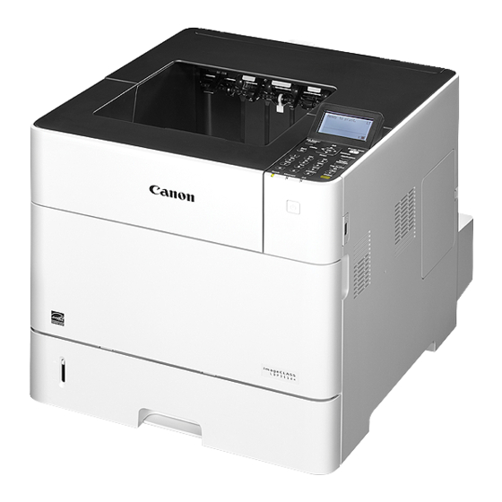
Page 18: List Of Parts
1. Product Overview List of Parts External [10] [11] [12] Name Name Upper Cover Unit USB-H (Front) Control Panel Upper Cover Front Cover USB-H (Rear 1) Cassette USB-H (Rear 2) Rear Cover (Sub Delivery Tray) USB-D Duplex Unit LAN Port... -
Page 19: Cross Sectional View
1. Product Overview Cross Sectional View [18] [17] [16] [15] [14] [13] [12] [11] [10] Name Name Delivery Roller [10] Multi-purpose Tray Separation Roller Fixing Film [11] Vertical Path Roller Laser Scanner Unit [12] Cassette Separation Roller Photosensitive Drum [13] Cassette Feed Roller Transfer Roller [14]... -
Page 20: Technical Explanation (Device)
Technical Explanation (Device) Laser Exposure System...... 14 Image Formation System....16 Pickup Feeding System...... 21 Fixing System........32 Controller System........36... -
Page 21: Laser Exposure System
2. Technical Explanation (Device) Laser Exposure System Overview The Laser Scanner system forms a latent image on the Photosensitive Drum according to the video signal sent from the Main Controller. The Laser Scanner Unit consists of the Laser Unit and the Scanner Motor Unit, and is controlled by the signal input from the DC Controller. - Page 22 2. Technical Explanation (Device) <Execution Timing> At startup of the Laser Scanner Motor <Control Description> 1. The DC Controller PCB forcefully rotates the Laser Scanner Motor. 2. Sends acceleration signals (ACC) and deceleration signals (DEC) to the Laser Scanner Motor to control the speed to the specified speed.
-
Page 23: Image Formation System
2. Technical Explanation (Device) Image Formation System Image Formation Process ■ Outline The image formation process consists of the following seven steps divided among five functional blocks: Latent image formation block • Step 1: Primary charging • Step 2: Laser-beam exposure Developing block •... -
Page 24: Developing Block
2. Technical Explanation (Device) Step 2: Laser-beam exposure The laser beam scans the photosensitive drum to neutralize the negative charge on portions of the drum surface. An electrostatic latent image forms where the negative charge was neutralized. Laser beam Unexposed area Exposed area ●... -
Page 25: Transfer Block
2. Technical Explanation (Device) ■ Transfer block During the two steps that comprise this block, a toner image on the photosensitive drum is transferred to the print media. Step 4: Transfer The transfer bias is applied to the transfer roller to charge the print media positive. The positively charged media attracts the negatively charged toner from the photosensitive drum surface. -
Page 26: Cartridge
2. Technical Explanation (Device) ■ Drum cleaning block The residual toner is cleared from the photosensitive drum surface. Step 7: Drum cleaning The cleaning blade scrapes the residual toner off the surface of the photosensitive drum. The residual toner is deposited in the toner collection box. -
Page 27: Memory Tag
This machine can detect and store the cartridge usage conditions and other information when the DC Controller PCB reads and writes the data stored in the memory tag. If the memory tag cannot be detected, "Error. Non-Canon cart. not covered by warranty" is displayed. ■ Cartridge Detection The DC Controller detects whether a cartridge is installed according to the change in primary charging current. -
Page 28: Pickup Feeding System
2. Technical Explanation (Device) Pickup Feeding System Overview The Pickup Feed System performs pickup, feed, and delivery of print paper, and consists of various rollers. Print paper flow Duplex delivery Face-down delivery Face-up delivery... - Page 29 2. Technical Explanation (Device) Load drives of electrical components M299 M1501 M102 M101 Lifting plate Registration shutter SL102 CL101 SL101 Lifter M1502 Pickup arm M103 Lifting plate Name Electric code Pickup Motor M101 Main Motor M102 Lifter Motor M103 Fixing Motor M299 Duplex Reverse Motor M1501...
-
Page 30: Various Control Mechanisms
2. Technical Explanation (Device) Outline drawing of sensors and rollers PS104 Face-down delivery roller Registration shutter Lifting plate PS108 Fiking sleeve Pre-transfer roller PS106 PS699 PS700 Photosensitive drum PS103 Pressure roller PS105 PS102 Transfer roller PS907 PS107 Feed roller Feed roller PS101 Separation roller Lifter... - Page 31 2. Technical Explanation (Device) DC controller Pickup arm PS907 PS107 PS101 Cassette paper sensor lever Lifter motor Paper Level Sensor lever M103 Lifter Lifting plate <Before lift-up operation> <After lift-up operation> This operation is divided into two operations: the initial lift-up operation and the lift-up operation during printing. 1.
- Page 32 2. Technical Explanation (Device) Paper size Size Switch Setting (SW102/SW1600) Upper Middle Lower No cassette EXECTIVE Universal ■ Cassette Pickup Control The DC Controller rotates the Pickup Roller by rotating the Pickup Motor (M101). The Pickup Arm is lifted and lowered to feed the paper by rotating the Pickup Cam with the Pickup Solenoid (SL101). DC controller Cassette pickup solenoid M101...
-
Page 33: Skew Correction
2. Technical Explanation (Device) DC controller M101 SL102 MP tray pickup solenoid MP tray MP tray feed roller Media pickup roller Lifting plate MP tray separation roller PS105 MP tray pickup sensor ■ Skew Correction This machine can correct paper skew without lowering throughput. Skew is corrected as follows. -
Page 34: Paper Width Detection
2. Technical Explanation (Device) Registration shutter Registration roller ■ Paper Width Detection Detection of paper width is performed to prevent temperature increase at the edge of the Fixing Heater. Width and position of paper being fed are detected by the Paper Width Sensor 1 and 2 (PS106/PS108). If the paper width detected by the Paper Width Sensors did not match the paper size set with the Cassette Size Switch, "Check paper size"... -
Page 35: Feed Speed Control
2. Technical Explanation (Device) Paper Width Sensor 1 Paper Width Sensor 2 Detection result Paper size (PS106) (PS108) Paper width: Wider than 198 mm A4, LTR, LGL Paper width: Shorter than 198 Executive, B5, A6 Paper position: Right side Paper position: Right side ■... - Page 36 2. Technical Explanation (Device) Name Electric code Envelope Pickup Motor M1800 Envelope Presence Sensor PS1800 Envelope Double Feed Sensor PS1802 ● Envelope Double Feed Detection The Envelope Feeder can detect double feeding. A double feed jam is detected when the Sensor Flag moves away from the Double Feed Sensor surface due to the paper thickness. <Normal-feed>...
-
Page 37: Jam Detection
2. Technical Explanation (Device) Name Electric code Envelope Sensor PS1800 Envelope Double Feed Sensor PS1802 ■ Jam Detection The sensors are provided at the locations shown below to detect the presence of print paper and whether the print paper is being fed correctly. - Page 38 2. Technical Explanation (Device) The printer detects the following jams. 1. Pickup delay jam 1 At paper pickup, the Registration Sensor (PS103) does not detect the paper leading edge although a specified period of time has passed. 2. Pickup delay jam 2 At the start of the pickup operation, sensors (PS102/PS1603/PS1704) do not detect the paper leading edge although a specified period of time has passed.
-
Page 39: Fixing System
2. Technical Explanation (Device) Fixing System Overview/Configuration ■ Overview Fixing Delivery Assembly consists of the Fixing Assembly for fixing toner on the print paper and the Delivery Assembly for delivering print paper on which toner is fixed to the Delivery Outlet (Face-down Tray, Face-up Tray). ■... - Page 40 2. Technical Explanation (Device) AC input Power Supply PCB DC controller /ZEROX Zero crossing circuit /RLD +24VC Fixing heater Relay Relay (RL102) safety circuit (RL101) CURRMS Current detection circuit FSRD1/FSRD2 Fixing heater drive circuit FSRTH2 /AC200 JP1001 +3.3V 100V: Open 200V: Close /HITMP Q704...
-
Page 41: Protective Functions
2. Technical Explanation (Device) DC controller M299 Fixing motor Fixing pressure release cam PS699 Pressure roller Fixing pressure release sensor Fixing sleeve <Pressurized> <Released> Execution condition/timing of disengagement operation: • At occurrence of a jam • Default status If disengagement operation is not performed although a specified period of time has passed, an error code is notified. <Related error codes>... -
Page 42: Fixing Assembly Failure Detection
2. Technical Explanation (Device) 3. Thermoswitch When the temperature of the Fixing Heater rises abnormally and the Thermoswitch (TP1) exceeds a certain temperature, the contact of the Thermoswitch is disconnected to shut down the power supply to the Fixing Assembly. ●... -
Page 43: Controller System
2. Technical Explanation (Device) Controller System Main Controller The Main Controller receives print information from the external equipment (host computer, etc.) via the interface cable. This print information includes commands to exchange the status or unique information of a printer and the PDL data of the image data. -
Page 44: Dc Controller
2. Technical Explanation (Device) DC Controller The DC Controller is a circuit to control the operation sequences of this machine, and controlled by the CPU in the DC Controller. The following explains the operation of the DC controller. 1. When the Power Switch of this machine is turned ON, DC power is supplied from the Power Supply PCB to the DC Controller. 2. -
Page 45: Power Supply
2. Technical Explanation (Device) J No. Connection destination Electric code Name J No. M101 Pickup Motor J191 PS101 Paper Sensor PS107 Paper Level Sensor 1 PS907 Paper Level Sensor 2 UN12 Laser Driver PCB J145 PS102 Pre-registration Sensor PS103 Registration Sensor PS106 Paper Width Sensor 1 PS108... -
Page 46: Quick Startup
2. Technical Explanation (Device) 3.3V 3.3V AC/DC All-night Power AC Relay PCB Sleep I/F PCB Supply PCB Main Controller DC Controller PCB 3.3V AC/DC DC/DC MOTER AC/DC FIXING Power Supply PCB 3.3V • +24 V: Motor, Solenoid, High-voltage Power Supply PCB, and Pickup Options •... -
Page 47: Energy Saving Function
2. Technical Explanation (Device) TCP/IP Settings > IPv6 Settings > ON TCP/IP Settings > IPv4 Settings > Protocol > BOOTP > ON TCP/IP Settings > IPv4 Settings > Protocol > RARP > ON When IPSec is set MEAP-related Information During execution of an MEAP application which prohibits quick startup When a login application is switched by SMS When a job is in progress (including internal jobs in progress such as calibration and cleaning) When importing setting values using service mode or RUI... -
Page 48: Technical Explanation (System)
Technical Explanation (System) Version Upgrade......... 42 Backup/Restoration......72 Monitoring Function (e-Maintenance/ imageWARE Remote)..... 88 MEAP Application Management..92... -
Page 49: Version Upgrade
3. Technical Explanation (System) Version Upgrade Overview The following methods exist for version upgrade the system of the device. Device Device Setup menu Setup menu PC for service SST menu SST menu Network connection Network connection System System System USB connection USB connection System System... -
Page 50: Version Upgrade Using Ust
3. Technical Explanation (System) Version Upgrade Using UST UST is included in the firmware for the machine that can be downloaded from the website of CINC. Firmware is downloaded as a zip file and a folder containing UST is extracted by decompressing the file. When executing UST on the PC connected to the machine with a USB Cable, the firmware can be upgraded by downloading it from the PC to the machine. - Page 51 / Partner 2) Notify distribution UGW Operator information to CDS. e-RDS 4) Download firmware Canon Inc. Firmware Upload Firmware Firmware Updater 5) Writing process is automatically started upon download completed. b. CDS Remote Download (download in conjunction with UGW) Firmware distribution can be performed before a service technician visits the customer by registering the distribution schedule in the device using UGW from UGW in advance.
-
Page 52: List Of Functions
/ Partner UGW Operator 3) Notify distribution e-RDS information to CDS. 5) Periodical firmware download Canon Inc. 1) Firmware Upload Updater 6) Writing process is automatically started upon download completed. ■ List of Functions The matrix below shows the list of functions provided by Updater. -
Page 53: Network Settings
3. Technical Explanation (System) Coexistence of Remote UI and other tools Users logged in SMS (Service Management Service) are unable to use Update functions from Remote UI. Using Updater function from Remote UI Upon the following operations done, Updater functions are suspended from Remote UI for certain duration. •... -
Page 54: Confirming Url Setting Of Distribution Server
3. Technical Explanation (System) NOTE: • In order to use linkage with UGW or functions of [Settings/Registration], the preparation for it shown below needs to be performed. • Enabling linkage with UGW • Enabling the display of [Delivered Installation] in [Install Applications/Options] in [Settings/Registration] menu •... - Page 55 (Unless asked to do so by the Support Dept. of the sales company or the Canon R&D.) Especially when the level 4 is set, the performance will be significantly lower and it will take time to collect logs.
- Page 56 3. Technical Explanation (System) 3. Click [Yes] when a dialog box confirming whether you want to execute the test is display. The Communication Test is carried out. 4. Upon the communication test completed, the communication test result screen is shown. Press [Back] button to exit this operation.
- Page 57 3. Technical Explanation (System) ● Remote UI Display Settings To display (hide) the menu for upgrading the version of firmware using Updater on the following Remote UI screen: [Settings/ Registration] > [Management Settings] > [License/Others] > [Register/Update Software] (hereinafter referred to as [Register/ Update Software] screen).
-
Page 58: Firmware Update Procedure
3. Technical Explanation (System) Specify this setting to allow users for the scheduled firmware update using the Updater function. This operation is not necessary if you do not want to allow users to do so. 1. Enter service mode. 2. Set "On" for the following service mode: •... - Page 59 3. Technical Explanation (System) 2. When using the Control Panel, execute the following service mode to update the firmware downloaded to the device using the Updater function. • SERVICE MODE > F/W UPDATE GR. > CDS F/W UPDATE GR. Execute? Executing...
- Page 60 3. Technical Explanation (System) ■ Updater Function Maintenance ● Checking Logs If an error occurs when upgrading the firmware using the Updater, a log can be checked on the [Register/Update Software] screen of the Remote UI. There are two types of logs; update logs and system logs. Update log A log regarding installation of system options/MEAP applications and firmware updates.
-
Page 61: Deleting Downloaded Firmware
3. Technical Explanation (System) ● Management of [Register/Update Software] The [Register/Update Software] menu enables you to apply and delete firmware downloaded to this machine. When distribution is scheduled by linking with UGW, those schedules can also be deleted. Applying Downloaded Firmware This section describes the procedure for applying firmware downloaded to this machine. - Page 62 3. Technical Explanation (System) ● Updater Error Messages Error messages displayed in Remote UI are shown below. As to error codes, see the next list. Messages Timing of dis- Cause Remedy play An error occurred In communicating System error occurred in Obtain the log etc.
- Page 63 3. Technical Explanation (System) Messages Timing of dis- Cause Remedy play Delivery Server : Communication In the communication test, Check the network environment of the device, and re-exe- Connect Failed test, etc. (commu- failed to connect to the de- cute the job. File Server : Re- nication test result livery server.
- Page 64 3. Technical Explanation (System) Messages Timing of dis- Cause Remedy play An error occurred. Notice of version Failed to acquire version in- Re-execute the job. Error Code: [xxx] information (main formation of device due to If it recurs, obtain the log etc. (Refer to "System Manage- screen) no CDS registration of firm- ment Operations"...
- Page 65 3. Technical Explanation (System) Messages Timing of dis- Cause Remedy play An error occurred. Immediate down- During the download, all After adding vacant space of the storage disk, re-execute Error Code: [xxx] load (error dia- space in the storage disk the job.
- Page 66 3. Technical Explanation (System) Messages Timing of dis- Cause Remedy play An error occurred. Manual update After the update, failed to Check the network environment and re-execute the job. Check the Update (main screen) Au- connect to the delivery If it recurs, obtain the log etc. (Refer to "System Manage- Firmware screen.
- Page 67 3. Technical Explanation (System) Messages Timing of dis- Cause Remedy play Restart failed. Manual update An error occurred at the After turning OFF and then ON the main power of the device, Turn the main pow- (error dialogue) time of the device restart. re-execute the job.
-
Page 68: Error Code List
3. Technical Explanation (System) Remedy by Error Code Remedy to Be Taken When an Error Code Starting with [81------] Is Displayed The remedy for an error code whose first two digits are "81" is shown below. 1. Refer to “List of Error Codes Starting with 81” on page 61 “List of Error Codes Related to Local CDS”... - Page 69 • The number of digits of E-mail Address (mailAd- number of the device.) dress) is larger than 128. (Canon Inc. Only) In the case of • Characters other than single-byte alphanumeric an error in Firm Type, Firmware characters and symbols are used for E-mail Address Version, or Firmware Group (mailAddress).
- Page 70 Company. (Attach information on the time of occurrence and the serial number of the device.) (Canon Inc. Only) Check regis- tration of LMS. 81xx1009 The retrieval type in the data entry items is special and Enter correct ID and the pass- there are no basic-set applicable to the registration ID and word.
- Page 71 3. Technical Explanation (System) Error Code Description Remedy Cause of error CDS server UP DATER Search the applicable firmware 81xx1015 When firmware distribution time-out occurs. again, and perform distribution A reception completion notification was not sent to CDS of the firmware. within 24 hours after the start of the distribution.
- Page 72 3. Technical Explanation (System) List of Error Codes Starting with a Number Other than 81 The list of error codes starting with a number other than 81 is shown below. If such an error has occurred, search the remedy using the last four digits of the error code. Report the error to the support department of the sales company with the Sublog and update log of the device.
- Page 73 3. Technical Explanation (System) Error Code Description Remedy Cause of error CDS server UP DATER Network 8xxx 36xx Contact the support department of the An internal error related to sales company. APL_CDS partition (Attach the Sublog and update log of the 37xx DCM-related service error device.)
- Page 74 3. Technical Explanation (System) Error Code Description Remedy Cause of error CDS server UP DATER Network 8xxx 4302 <In the case of scheduled up- <In the case of scheduled update> date> Specify the distribution settings again, In response to a download start making sure that the distribution server notification sent from the de- maintenance time and the scheduled up-...
- Page 75 3. Technical Explanation (System) Error Code Description Remedy Cause of error CDS server UP DATER Network 8xxx 5206 An HTTP status code other Check the network environment of the de- than 206 or 200 was returned vice (such as the examples shown below). from HTTP.
- Page 76 3. Technical Explanation (System) Error Code Description Remedy Cause of error CDS server UP DATER Network 8xxx 530A A privilege error during creation Check the network environment of the de- of a file vice and start the operation again. 530B A privilege error during output of a file 530C...
- Page 77 3. Technical Explanation (System) Error Code Description Remedy Cause of error CDS server UP DATER Network 8xxx 7504 (Attach the Sublog and update log of the There is no download list infor- device.) mation. Internal module Axxx Communication error in the in- Contact the support department of the ternal module sales company.
- Page 78 3. Technical Explanation (System) Error Description Remedy Code 8xxx0709 At the time of firmware update, the Tracking ID ordered Obtain the sublog, and contact the support department of the sales by UGW and the one to which the Updater responded company.
-
Page 79: Backup/Restoration
3. Technical Explanation (System) Backup/Restoration Depending on the works to be done such as replacing parts, this data needs to be backed up and restored. There are some ways to back up and restore data, and the appropriate one should be used depending on the purpose and storage destination. - Page 80 3. Technical Explanation (System) Backup/Restoration Using Service Mode Some of the functions in service mode can be used to backup and restore data. The setting value information and service counter values of each controller can be backed up and restored. ●...
- Page 81 3. Technical Explanation (System) ■ Import/Export Procedure from [Settings/Registration] of Remote UI This section describes the procedure for backing up and restoring service mode setting information by using the [Import/Export] function in the [Settings/Registration] menu of Remote UI. CAUTION: • The service mode setting information can be backed up and restored only from the [Settings/Registration] menu on Remote UI, and the operation cannot be performed from the [Settings/Registration] menu on the Control Panel.
- Page 82 3. Technical Explanation (System) 2. Exit service mode, start remote UI, log in as a system administrator, and then select the following item: • [Settings/Registration] > [Import/Export] > [Import] 3. After confirming that [Service Mode] is displayed/selected in [Select Item to Export], enter the password and click [Start Exporting].
- Page 83 3. Technical Explanation (System) 5. Enter service mode, and set the following item to "0". • SERVICE MODE > FUNCTION GR. > SMD-EXPT CAUTION: Since the screen of export function can also be accessed by the user, be sure to disable the [SMD-EXPT] setting (setting value: 0).
- Page 84 3. Technical Explanation (System) 3. Configure the import setting, and click [Start Importing]. Entering the encryption password and clicking [Start Importing] imports the menu option data. [Browse..]button Click to select the file to import. Decryption Password Enter up to 32 alphanumeric characters for the password that was set when the file was exported. 4.
- Page 85 3. Technical Explanation (System) The following USB flash drives can be used for export/import. • USB flash drive in FAT 16 format (storage capacity: 2 GB) • USB flash drive in FAT 32 format (storage capacity: 32 GB) Note that the descriptions in parenthesis in the procedure are the descriptions in the case of remote UI. 1.
- Page 86 3. Technical Explanation (System) 3. Access the following service mode from the Control Panel, specify the file to import, enter the encryption password, and press the [OK] key. • SERVICE MODE > FUNCTION GR. > Import Export Set. >IMPORT SERVICE MODE FUNCTION GR.
-
Page 87: Backup/Restoration Using A Function Other Than The Dcm Function
3. Technical Explanation (System) ● Procedure for Importing from a PC 1. Prepare the setting information file (".dcm" file) to import. 2. Access the following service mode in the Remote UI from a PC browser, specify the file to import, enter the encryption password, and click [Start Importing]. - Page 88 3. Technical Explanation (System) 2. Execute the following service mode to export the setting values in the machine to the USB flash drive. • SERVICE MODE > FUNCTION GR. > ECONF > EXPORT > ALL > Yes SERVICE MODE FUNCTION GR. ECONF EXPORT Execute?
-
Page 89: Target Data For Backup
3. Technical Explanation (System) ■ Backup/restoration using the Expansion ROM for servicing and the Sublog Board Use the Expansion ROM for servicing and the Sublog Board to migrate the setting information in a failed Main Controller PCB to an unused Main Controller. Target data for backup Target data for backup is as follows: (For details, see [Appendix] >... - Page 90 3. Technical Explanation (System) 1. Disassemble the Sublog Board [1], and replace the spacer (short) [1] and the spacer (long) [3] with each other. • 1 screw [4] CAUTION: Because the screw [4] is a molded part, do not tighten it too much. Otherwise, it may be damaged. Installing the Expansion ROM for servicing and Sublog Board 1.
- Page 91 3. Technical Explanation (System) 3. Install the above Sublog Board to the machine. Expansion ROM Sublog Board Main Controller PCB CAUTION: Connect a PCB (Expansion ROM for servicing and Sublog Board) which has the setting information backed up, to an unused Main Controller PCB.
- Page 92 3. Technical Explanation (System) 3. The following message is displayed when backup is completed successfully. 4. Turn OFF the power, and remove the faulty Main Controller PCB and the Sublog Board to which data was exported. CAUTION: Since data cannot be migrated to a Main Controller PCB that has been used before, connect an unused Main Controller PCB to the Sublog Board and Expansion ROM PCB where the data has been backed up (exported to) before installing it to the machine.
- Page 93 3. Technical Explanation (System) CAUTION: If the Main Controller PCB has not been replaced with an unused Main Controller PCB, the following message is displayed and the operation stops. In this case, turn OFF the power, and replace the Main Controller PCB with an unused Main Controller PCB.
-
Page 94: List Of Error Messages
3. Technical Explanation (System) List of Error Messages The following messages are displayed when certain failures occur during operation. List of Messages Detail Sublog board not found Sublog Board is not installed. NVRAM read error Export cannot be executed because the faulty Main Controller PCB is too damaged to retrieve information. -
Page 95: Monitoring Function (E-Maintenance/Imageware Remote)
3. Technical Explanation (System) Monitoring Function (e-Maintenance/imageWARE Remote) Overview of System ■ Function Overview Embedded RDS (hereinafter referred to as E-RDS) is a monitoring program that runs on the host machine. When the monitoring option is enabled by making the setting on this machine, information such as the status change of the machine, counter information, and failure information are collected. -
Page 96: Cautions When Using E-Rds
3. Technical Explanation (System) Functional cat- Sub category Description egory Data transmis- Sublog Send data such as device Sublogs and DCON logs to the server. sion: Operation in- Operation check Contact the server to check if there is processing to be executed, and receive struction following instructions if any. -
Page 97: Setting Items
3. Technical Explanation (System) ■ Setting Items Configure E-RDS in service mode. The setting items are described below. Example of the Remote UI Screen SERVICE MODE SERVICE MODE NETWRK GR. PANEL LOCK GR. PANEL LOCK GR. BUFFER LIMIT F/W UPDATE GR. Check Counter E-RDS NETWORK GR. -
Page 98: Maintenance
3. Technical Explanation (System) 1. Open the following service mode, and confirm that the URL for accessing UGW is set correctly. If the correct URL is not set, set it. • SERVICE MODE > NETWORK GR.> E-RDS > RGW-ADDRESS E-RDS RGW-ADDRESS E-RDS SWITCH https://a01.ugwdevice.net/u... -
Page 99: Meap Application Management
3. Technical Explanation (System) MEAP Application Management About MEAP MEAP (Multifunctional Embedded Application Platform) is an application platform (execution platform) that allows the user to execute an application written in the Java language on a Java virtual machine installed on the device. In this chapter, a device with MEAP is called a device supporting MEAP, and an application which runs on MEAP is called a MEAP application. -
Page 100: Initial Display Languages Of Sms
3. Technical Explanation (System) Example of the SMS screen ■ Preparation of PC for Accessing SMS ● Checking of operation environment The PC and browser used to access SMS require the following system environment. Combination of the Browser and the OS Supported browser Windows XP Professional SP3 Internet Explorer 7... - Page 101 3. Technical Explanation (System) ■ Device compatibility with the MEAP application To find out whether the device is compatible with the MEAP application, check the devices supported by the MEAP application. Depending on the application, the device's firmware may require version upgrade. ■...
-
Page 102: Managing The License File
Application System Information Application Name: C-Cabinet Gateway for MEAP Application ID/System Application Name: 03a46668-63e4-4636-9cbb-492b6cef05d5 Application Version: 1.0.0 Status: Resolved Installed: Tue Oct 21 14:00:11 GMT+09:00 2003 Vendor : Canon Inc. License Status : Installed Maximum Memory Usage : 1024 Registered Service :... - Page 103 3. Technical Explanation (System) Content of MEAP system information Item content Application Name It is the name (bundle-name) declared in a statement within the application program. It may not necessarily be identical to the name of the program. Application ID/System Application Application ID (application-id) items which are declared on the declaration statement in the ap- Name plication program are printed.
-
Page 104: Setting Procedure
3. Technical Explanation (System) Ver 58 of MEAP Specifications supports this service. The collected logs can be downloaded or deleted in user mode. The settings such as the log level to be saved cannot be made from SMS. These settings depend on the MEAP application. For detailed information, refer to the manual for the application. ●... - Page 105 3. Technical Explanation (System) Network Settings (Remote UI) Select [Setup] > [Network] > [Remote UI Settings] from the setup menu to activate the Remote UI function. ([ON] is specified at the time of shipment.) For details on the work procedure, refer to e-Manual [ Top page ] > [ Setting Menu List ] > [ Setup Menu ] >...
- Page 106 3. Technical Explanation (System) Specify an application file (.jar) and license file (.lic) on the [Install MEAP Application] page of SMS. For details on the procedure, see [Top Page] > [MEAP Application Settings] > [Installing MEAP Applications] in "Function Guide for MEAP Application Management".
-
Page 107: License Management
3. Technical Explanation (System) For details on the procedure, see [Top Page] > [MEAP Application Settings] > [Starting/Stopping MEAP Applications] in "Function Guide for MEAP Application Management". MEAP Application Authentication Information Settings When executing jobs from an application that does not require a printer operation, it is necessary to set authentication information in advance. - Page 108 3. Technical Explanation (System) ● Procedure for Downloading a License for Forwarding 1. Log in to SMS, stop the application to be forwarded. 2. Move to the download page of license forwarded for the device as sender (https:// <IP address of device>:8443/sms/ ForwardLicense).
- Page 109 3. Technical Explanation (System) 5. The window to confirm whether to create a transfer license will be displayed. Click [Yes]. 6. When [Download] on the [Download / Delete Transfer License File] becomes effective, click [Download]. 7. Specify the preservation place of the file according to the instruction of the screen. 8.
- Page 110 3. Technical Explanation (System) Change Login Application Procedure If multiple login applications are installed , you can activate the login application that you wish to use by accessing the [Enhanced System Application Management] screen of SMS, clicking the [SWITCH] button of the login application, and restarting this machine.
- Page 111 3. Technical Explanation (System) Login Service Uninstallation Procedure To uninstall a login application, access the [Enhanced System Application Management] screen of SMS, stop the corresponding login application (change its status to "Installed"), and click the [Uninstall] button. For details on the procedure, see [Top Page] >...
-
Page 112: Maintenance
3. Technical Explanation (System) Maintenance ■ When Replacing the PCB ● Special license for reinstallation When replacing the PCB, a special license file is required to reinstall the application with the expiration date of the current counter value migrated as it is. This special license file is handled as a service tool and cannot be obtained by end users. In order to obtain a special license file, the service technician needs to contact the person in charge of support at the sales company. -
Page 113: Work Procedure
3. Technical Explanation (System) Since the system is automatically formatted when E616 is displayed, the installed MEAP applications will disappear and the device's MEAP function itself will also be disabled. For this reason, it is necessary to enable the MEAP function and then reinstall the MEAP applications. ●... - Page 114 3. Technical Explanation (System) CAUTION: If the device has been started in the MEAP SAFE mode, all MEAP applications stop and the status becomes "Installed". This status remains unchanged even if the MEAP SAFE mode is cancelled and the device is started again in normal mode. It is therefore necessary to access SMS after normal startup, and start the MEAP application.
-
Page 115: Periodical Service
Periodical Service Periodically Replaced Parts....109 Consumable parts......110 Periodical Service......111... -
Page 116: Periodically Replaced Parts
4. Periodical Service Periodically Replaced Parts Periodically Replaced Parts • Periodic replacement parts are not required in this machine. -
Page 117: Consumable Parts
4. Periodical Service Consumable parts Type Name Parts number *1 Q'ty Estimated Service Remarks life *2 Task Main Body Fan1 RK2-1988 40,000 Replace hours Fan2 RK2-1989 40,000 Replace hours Fan3 RK2-3244 40,000 Replace hours Fan4 RK2-1992 40,000 Replace hours Fixing Assembly 120V : RM1-6308 22,5000 pa- Replace... -
Page 118: Periodical Service
4. Periodical Service Periodical Service Periodical Service • No periodic services are required to this machine. -
Page 119: Parts Replacement And Cleaning
Parts Replacement and Cleaning List of Parts........113 External Cover/Interior System..116 Controller System......123 Laser Exposure System....130 Image Formation System....131 Fixing System........134 Pickup/Feed System......135... -
Page 120: List Of Parts
5. Parts Replacement and Cleaning List of Parts Main Unit Name Reference Laser Scanner Unit “ Removing the Laser Scanenr Unit” on page 130 Lifter Drive Unit Pickup Drive Unit “Removing the Pickup Drive Unit” on page 138 Vertical Path Roller “Removing the Verticalpass Roller”... -
Page 121: Motor/Fan
5. Parts Replacement and Cleaning Motor/Fan Symbol Name Reference M299 Fixing Motor “Removint the Fixing Moter” on page 134 FN102 Fan 2 “Removing the Fan2” on page 121 M102 Main Motor “Removing the Main Motor” on page 131 FN101 Fan 1 “Removing the Fan1”... -
Page 122: Pcb
5. Parts Replacement and Cleaning Name Reference PS101 Paper Sensor PS102 Pre-registration Sensor PS103 Registration Sensor PS104 Delivery Full Sensor PS105 Multi-purpose Tray Sensor PS106 Paper Width Sensor 1 PS107 Media Stack Surface Sensor 1 PS108 Paper Width Sensor 2 PS699 Fixing pressure release sensor PS700... -
Page 123: External Cover/Interior System
5. Parts Replacement and Cleaning 3. Remove the Upper Rear Cover [1]. External Cover/Interior • 1 Screw [2] System Removing the Left Cover ■ Preparation 1. Pull out the Cassette. 2. Remove the Upper Cover. 3. Open the MP-Tray. 4. Remove the Duplex Unit. ■... -
Page 124: Removing The Right Cover
5. Parts Replacement and Cleaning 6. Release the claws while lifting the Upper Cover and 3. Remove the Right Cover [1]. the Left Inner Cover, and remove the Left Cover [1]. • 4 Screws [2] • 5 Claws [2] • 4 Claws [3] •... -
Page 125: Removing The Front Cover Unit
5. Parts Replacement and Cleaning ■ Procedure 3. Release the protrusion [1] from the rail. • 2 Protrusions [1] 1. Remove the Rear Cover [2] while bending the [1] part shown in the figure. • 2 Bosses [3] Removing the Front Cover Unit ■... -
Page 126: Removing The Upper Cover Unit
5. Parts Replacement and Cleaning ■ Procedure 2. Remove the Right Cover.“ Removing the Right Cover” on page 117 1. Remove the Rear Right Cover [1]. 3. Remove the Front Cover.“ Removing the Front • 1 Claw [2] Cover Unit” on page 118 •... -
Page 127: Removing The Control Panel
5. Parts Replacement and Cleaning ■ Procedure 3. Remove the Upper Cover Unit [1]. • 4 Screws [2] • 1 Link [3] 1. Remove the Control Panel [1]. • 2 Screws [2] • 2 Connectors [3] CAUTION: Points to Note at Removal Be careful of the connector on the back. -
Page 128: Removing The Fan2
5. Parts Replacement and Cleaning ■ Procedure 5. Remove the Left Cover.“ Removing the Left Cover” on page 116 1. Remove the Fan 1 [1]. ■ Procedure • 1 Connector [2] • 1 Screw [3] 1. Remove the plate [1]. •... - Page 129 5. Parts Replacement and Cleaning 5. Remove the Left Cover.“ Removing the Left Cover” on page 116 ■ Procedure 1. Remove the plate [1]. • 2 Screws [2] 2. Remove the Fan Retainer Plate [1], and remove the Fan 4 [2]. •...
-
Page 130: Controller System
5. Parts Replacement and Cleaning • SERVICE MODE > FUNCTION GR. > ECONF > Controller System EXPORT • SERVICE MODE > FUNCTION GR. > Import/Export Set. > EXPORT Removing the Controller • Setup > User Maintenance > Import/Export Set. > Export •... -
Page 131: Removing The Controller Box
5. Parts Replacement and Cleaning ■ Procedure 2. Remove the Main Controller PCB [1]. • 6 Connectors [2] • 1 Flexible Cable [3] 1. Disconnect the connectors and free the harness • 1 USB Cable [4] from the Wire Saddles. •... -
Page 132: Removing The Dc Controller Pcb
5. Parts Replacement and Cleaning 4. Remove the Right Cover.“ Removing the Right 3. Remove the Cable Lower Cover [1]. Cover” on page 117 • 1 Boss [2] • 2 Hooks [3] 5. Remove the Main Controller PCB.“Removing the Main Controller PCB” on page 123 6. -
Page 133: Removing The Ac Relay Pcb
5. Parts Replacement and Cleaning ■ Procedure Removing the AC Relay PCB 1. Remove the DC Controller PCB [1]. ■ Preparation • 29 Connectors [2] • 1 Flexible Cable [3] 1. Remove the Right Cover.“ Removing the Right • 2 Screws [4] Cover”... - Page 134 5. Parts Replacement and Cleaning 10. Remove the Power Supply Box.“Removing the 3. Remove the Harness Guide [1]. Power Supply Box” on page 124 • 2 Screws [2] • 1 Spring [3] 11. Remove the Left Cover.“ Removing the Left Cover” •...
- Page 135 5. Parts Replacement and Cleaning 5. Pass the harness [1] through the hole [2]. 7. Separate the Feed Guide [1] and the Power Supply PCB [2]. • 6 Screws [3] • 6 Bosses [4] • 1 Hook [5] 6. Pull out the Power Supply PCB [1]. CAUTION: •...
-
Page 136: Removing The All-Night Power Supply Pcb
5. Parts Replacement and Cleaning ■ Procedure Removing the All-Night Power Supply PCB 1. Remove the Sleep Interface PCB [1]. • 9 Connectors [2] ■ Preparation • 2 Screws [3] • 1 Wire Saddle [4] • 1 Hook [5] 1. Remove the Right Cover.“... -
Page 137: Laser Exposure System
5. Parts Replacement and Cleaning 2. Remove the Scanner Retainer [1]. Laser Exposure System • 2 Claws [2] Removing the Laser Scanenr Unit ■ Preparation 1. Open the Upper Cover. 2. Pull out the cassette. 3. Remove the Right Cover.“ Removing the Right Cover”... -
Page 138: Image Formation System
5. Parts Replacement and Cleaning Image Formation System CAUTION: Points to Note When Installing the Transfer Roller • Remove the orange Protector Paper [1] on a new Removing the Transfer Roller Transfer Roller only after installation. ■ Preparation 1. Open the Upper Cover. 2. -
Page 139: Removing The Main Drive Unit
5. Parts Replacement and Cleaning ■ Procedure ■ Procedure 1. Remove the Main Motor [1]. 1. Remove the Harness Guide [1] while avoiding the harness. • 1 Connector [2] • 3 Screws [3] • 1 Screw [2] • 1 Connector [3] •... - Page 140 5. Parts Replacement and Cleaning 3. Remove the Main Drive Unit [1]. • 4 Screws [2]...
-
Page 141: Fixing System
5. Parts Replacement and Cleaning ■ Procedure Fixing System 1. Remove the Harness Guide [1]. • 2 Screws [2] Removing the Fixing • 1 Spring [3] Assembly • 2 Bosses [4] ■ Preparation 1. Remove the Duplex Unit. 2. Remove the Rear Cover Unit.“Removing the Rear Cover”... -
Page 142: Pickup/Feed System
5. Parts Replacement and Cleaning 3. Remove the Feed Roller [1]/Separation Roller [2]. Pickup/Feed System • 2 Claws [3] Removing the Duplex Unit ■ Procedure 1. Remove the Duplex Unit [1]. Removing the MP-Tray Pickup/Feeding/Separation Roller ■ Procedure Removing the Pickup/ Feeding/Separation Roller 1. -
Page 143: Removing The Verticalpass Roller
5. Parts Replacement and Cleaning 4. Remove the Multi-purpose Tray Pickup Roller [1]/ ■ Procedure Feed Roller [2]. 1. Remove the Verticalpass Roller [1]. • 2 Screws [2] 5. Remove the Multi-purpose Tray Separation Roller [1]. • 1 Claw [2] Removing the Lifter Motor ■... -
Page 144: Removing The Mp-Tray Pickup Unit
5. Parts Replacement and Cleaning 2. Remove the Right Cover.“ Removing the Right ■ Procedure Cover” on page 117 1. Free the harness. ■ Procedure • 2 Connectors [1] 1. Remove the Pickup Motor [1]. • 1 Connector [2] • 3 Screws [3] 2. -
Page 145: Removing The Registration Roller Unit
5. Parts Replacement and Cleaning 2. Close the Registration Retainer [1], and remove the CAUTION: Registration Roller Unit [2]. Points to Note at Installation • 4 Screws [3] Be sure to route the harness [1] around the protrusion [2]. Removing the Registration Roller Unit ■... - Page 146 5. Parts Replacement and Cleaning 11. Remove the Fan 1.“Removing the Fan1” on page Installation Outline Drawing 12. Remove the Main Drive Unit.“Removing the Main Drive Unit.” on page 132 ■ Procedure 1. Remove the Drive Shaft [1] and the gear [2]. •...
-
Page 147: Adjustment
Adjustment Actions after Replacement....141... -
Page 148: Actions After Replacement
6. Adjustment Actions after Replacement Before Replacing the Main Controller PCB The following setting values are recorded in the Main Controller PCB. When the Main Controller PCB is replaced, these setting values are all returned to the default unless they are restored. •... -
Page 149: Troubleshooting
Troubleshooting Test Print...........143 Troubleshooting........ 147 Obtaining Debug Log......149... -
Page 150: Test Print
7. Troubleshooting Test Print Overview Printing test pages helps determine if the printer is functioning. CAUTION: There are two types of test pages: engine-test page and Main Controller-test page. Print a test page to make sure the printer engine and the Main Controller are functioning. ■... - Page 151 7. Troubleshooting Test Print Pattearn image check item image Grid chart Right angle accuracy, Straight line accuracy (printing continues until it is canceled by the Job Status/ Cancel key) Print "E" in Continuous printing the entire (printing continues until it is canceled by the Job Status/ area.
- Page 152 7. Troubleshooting Test Print Pattearn image check item image Grid chart Right angle accuracy, Straight line accuracy Character Character confirmation chart Halftone/ Right angle accuracy, Straight line accuracy Grid chart Solid white Fogging Image fail- For checking smeared image ure diagno- sis chart Software For checking the supported software counter...
-
Page 153: Device Log List
7. Troubleshooting 2. Press the [OK] key. The screen to choose whether to stop appears. 3. Select "Yes", and press the [OK] key. Device Log List Print jam, error and alarm logs. NOTE: Method to display the test print It appears in the menu by pressing [Job Status/Cancel] + [Utility] simultaneously. Purpose of use Log1 Jam log list... -
Page 154: Troubleshooting
When an image failure occurs, perform the remedy by referring to the following material. • User's Guide > Top > Troubleshooting > When You Cannot Print Properly NOTE: URL of User's Guide -> http://canon.com/oip-manual Repetitive Image Defects Ruler Component Distance between... - Page 155 7. Troubleshooting 15mm Media feed direction Center of letter sized paper 15mm 1. The center value (a), left value (b) and right value (c) are within 9.5 +/- 1.5 mm respectively. 2. The values obtained by a-b, b-c, and a-c are 1.5 mm or less respectively. If either of the above conditions are not satisfied, fixing failure may occur.
-
Page 156: Obtaining Debug Log
7. Troubleshooting Obtaining Debug Log Function Overview Debug logs (hereinafter "Sublogs") are logs that record the internal operations of the Main Controller, and are used to analyze program operations and used by developers to identify problems. When a problem that is difficult to reproduce occurs, collecting a Sublog immediately after the problem has occurred on site can increase the efficiency of analyzing the problem and reduce the time it takes to deal with the problem. -
Page 157: Sublog Collection Procedure
7. Troubleshooting Sublog Collection Procedure 1. Push SW1 on the board and confirm that LED1 turns on. If LED1 does not turn on, You need change the battery on Sublog board is located at BATS1 (CR2032) . CAUTION: There is danger of explosion if the battery is replaced with an incorrect type. Replace it only with the same type of battery. - Page 158 7. Troubleshooting 7. Insert the USB flash drive into the host machine. 8. Turn ON the power while pressing down the "<- " , "OK" and "Online" simultaneously. 9. Press the left arrow key or the right arrow key on the Control Panel until the "LOG TO USBMEM" menu is displayed. UPDATE:LANC →/↓...
- Page 159 7. Troubleshooting 10. Press the down arrow key on the Control Panel, and check that "DL-T DATA WRITE Do not turn the main power OFF." is displayed. CAUTION: The log is written when the machine is restarted the next time after the Sublog Board is attached. Therefore, make sure to quickly turn OFF the power after the problem has occurred and write to the USB flash drive to collect the log for the problem.
-
Page 160: Error/Jam/Alarm
Error/Jam/Alarm Overview........... 154 Error Code Details......155 Jam Code..........160 Alarm Code........163... -
Page 161: Overview
8. Error/Jam/Alarm Overview This section describes the error codes that are displayed when failure has occurred. The codes are divided into three categories. The codes can be checked by printing the device log list. Code types Description Error codes This code is displayed when a failure which impacts printing has occurred. Jam code This code is displayed when a jam occurs inside the machine. -
Page 162: Error Code Details
8. Error/Jam/Alarm Error Code Details Error Code Title Detection description Remedy A4-nn-Error System error System error - Turn OFF and then ON the main power. If the error persists, obtain the following information and contact the department in charge of quality management. - Page 163 8. Error/Jam/Alarm Error Code Title Detection description Remedy E004-0000 Fixing Drive As- Error in either the Fixing Heat- 1. Check the drawer connector between the Fixing Assembly and sembly circuit error er or the Fixing Motor the Power Supply PCB. 2. Check the connection of the Fixing Motor. 3.
- Page 164 8. Error/Jam/Alarm Error Code Title Detection description Remedy E245-1012 Host machine Host machine FRAM write er- 1. Replace the Main Controller PCB. FRAM write error ror was detected. E245-1013 Host machine Host machine FRAM write er- 1. Replace the Main Controller PCB. FRAM write error ror was detected.
- Page 165 8. Error/Jam/Alarm Error Code Title Detection description Remedy E602-1112 Device access er- Device access error (MEAP- Turning OFF and then ON the main power executes auto recovery. ror (MEAP-related) related) Since E616-0001 may be displayed in some cases, execute the remedy for E616-0001.
- Page 166 8. Error/Jam/Alarm Error Code Title Detection description Remedy E740-0004 Network Chip error Controller Chip access error 1. Turn OFF and then ON the power. 2. Replace the Main Controller detection PCB. E744-0800 Model code mis- Mismatch between the model 1. Replace the Main Controller PCB. match information of the Main Con- troller PCB and the model in-...
-
Page 167: Jam Code
8. Error/Jam/Alarm Jam Code PS106 PS103 PS108 PS105 PS102 PS700 PS1502 PS1603 PS1603 PS1603 PS1704 PS1802 PS106 PS108 PS103 PS102 PS1501 PS700 PS1503 PS1502... - Page 168 8. Error/Jam/Alarm High Sensor ID Sensor Name Type Area Order Order PS105 Multi-purpose Tray Sensor Pickup Delay Jam 1 Multi-purpose Tray PS102 Pre-registration Sensor Pickup Delay Jam 1 Cassette 1 PS1502 Duplex Re-pickup Sensor Pickup Delay Jam 1 Duplex pickup area PS102 Pre-registration Sensor Pickup Delay Jam 2...
- Page 169 8. Error/Jam/Alarm High Sensor ID Sensor Name Type Area Order Order PS700 Fixing Outlet Sensor Door Open Jam (*1) Fixing Roller toDelivery Area PS103 Registration Sensor Wrap Jam Registration Area to Cartridge PS106/PS108 Paper Width Sensor 1 / Paper Width Sensor 2 Wrap Jam Cartridge to Fixing Roll- er Area...
-
Page 170: Alarm Code
8. Error/Jam/Alarm Alarm Code Alarm Code Details Cause 06 - 0002 Fixing Assembly Alarm Fixing Assembly Life... -
Page 171: Service Mode
Service Mode Overview........... 165 Service Mode........169... -
Page 172: Overview
9. Service Mode Overview Entering Service Mode For information on how to enter service mode, contact the Support Dept. of the sales company. Remote UI Service Mode ■ Function Overview It is possible to display, configure, and execute various service mode modes as well as restart the host machine by using remote ■... -
Page 173: Service Report
9. Service Mode 2. Enter the password, and click [LOGIN]. Password required for authentication differs depending on the following service mode setting: SERVICE MODE > OPTION GR. > PSWD-SW Combinations of service mode settings and required passwords PSWD-SW Password required for authentica- Authentication screen setting tion... - Page 174 9. Service Mode CAUTION: When P-PRINT is printed and output, items set to a value other than the default value are marked. Configuration Page LBPxxx RAM Size : xxxxMB Main Controller Version : Rx.xx/PH Bxx.xx DCON Version : x.xx.xx Model : xxxx Option Drawer Version : OPT:xx.xx Font Version : 00000000 ●...
- Page 175 9. Service Mode ● Output Procedure (from the Remote UI Service Mode to a PC) 1. Select the following service mode from the Remote UI service mode, enter the password, and click [Start Exporting]. • SERVICE MODE > FUNCTION GR. > MISC-P > RPT2DL 2.
-
Page 176: Service Mode
9. Service Mode Service Mode COUNTER GR. * : Default Value Item Description FIXER COUNTER To set the accumulated number of sheets for the counter of the Fixing Assembly. When replacing the Fixing Assembly, execute "Setup > User Maintenance > Initialize Counter" to clear the counter. -
Page 177: Function Gr
9. Service Mode Item Description CHANGE CRG WARN LV To switch display/hide of the menu for setting the toner check timing (Setup > User Maintenance > Toner Check Timing). • OFF, ON * PSWD-SW Setting of the password type used to log in to remote UI service mode •... - Page 178 9. Service Mode Item Description USB-H To set to enable/disable the USB host function. By turning ON the host function, USB flash drive can be used. CAUTION: Points to note when pulling out the USB flash drive • Be sure to pull out the USB flash drive after turning USB-H to OFF because the USB flash drive is in the connected state when USB-H is ON.
-
Page 179: Log Gr
9. Service Mode Item Description IPMTU To change MTU size of network packet. Use this item when performing communications between locations (such as SEND) connected with Ethernet in a field environment where MTU black hole problem occurs (NTT/FLET'S). • 1 to 10 NOTE: [Description of terminology] •... -
Page 180: Panel.gr
9. Service Mode Item Description DEBUGLOG-MODE • Mode 1 The file name of the debug log is fixed. When the number of debug logs exceeds the maximum number of logs that can be saved at saving of debug logs, the latest debug log file is deleted to save the new file. - Page 181 9. Service Mode Item Description E-RDS SWITCH Set use/no use of Embedded-RDS function • ON: Use Embedded-RDS. • OFF: Do not use Embedded-RDS. Default Value : • Except China model : On*/Off • China model : On/Off* RGW-AD- To check and set the server URL. Use the "up, down, left and right keys, Job Status/Cancel key and Feeder DRESS selection key"...
-
Page 182: Sp.admin.mode
9. Service Mode Item Description IKEINTVL To set the IKE retry interval (seconds). • 1 to 30 (* Default value: 5) SPDALDEL To set whether to initialize the device at next startup. Be sure to return this value to "0" after initialization is completed. -
Page 183: Appendices
APPENDICES Service Tools........177 General Circuit Diagram....178 Backup Data List....... 181 List of Items Which Can Be Imported ............182 Soft counter specifications....184... -
Page 184: Service Tools
Service Tools Service Tools Solvents and Oil List Type Purpose Remark Ethyl alcohol • Cleaning: • Purchase locally metal part, oil stains, toner stains • Keep away from flame... -
Page 185: General Circuit Diagram
General Circuit Diagram General Circuit Diagram General Circuit Diagram (1/3) Front type A UN11 LCD Unit Memory PCB SOFT-ID PCB Card Main Switch SD Card J2801 type A type A type B Slot Mini B J200 J106 J128 J830 100V J110 Micon Write JTAG ICE... -
Page 186: General Circuit Diagram (2/3)
General Circuit Diagram General Circuit Diagram (2/3) Laser Scanner Unit M299 Scanner Motor Fixing Motor J143 Main PS699 PS700 Thermistor Thermistor Fixing Fixing TP61 UN12 Thermoswitch UN13 10 9 J221 Inlet Outlet TB617 TB618 Laser Driver PCB BD PCB Sensor Sensor J145 J929... -
Page 187: General Circuit Diagram (3/3)
General Circuit Diagram General Circuit Diagram (3/3) Duplex Unit M1501 M1502 PS1503 Duplex Duplex Side Registration Guide Reverse Re-pickup Homeposition Motor Motor Sensor J1520 J1521 J1522 J1503 J1506 J1505 PS1501 1 2 3 Duplex Face-up FU_DR Sensor UN14 J1500 1 2 3 4 FUSNS J1501 Duplex Driver PCB... -
Page 188: Backup Data List
Backup Data List Backup Data List Backup Data Data Location Replacement Delete Method Backup by User Backup by Service Setup Service Function DC Control- Main Control- Initialize Menu Network > Init. User Mainte- Service Mode Yes/No Method Location Yes/No Method Location ler PCB ler PCB... -
Page 189: List Of Items Which Can Be Imported
List of Items Which Can Be Imported List of Items Which Can Be Imported The following shows the items to be imported for this model. Note that the setting values are not imported in cases such as below: • Items which are originally not included in a DCM file (e.g.:"Settings/Registration Basic Information" of a DCM file exported using service mode) •... - Page 190 List of Items Which Can Be Imported Initial screen Large Small Case A Case B Case C RGW-ADDRESS RGW-PORT WOLtrans PROXYRES IPSEC SETTING IKERETRY IKEINTVL SPDALDEL IPSDEBLY PFW SETTING ILOGKEEP ILOGMODE IPTBROAD EAPOL_WT GCP-URLC...
-
Page 191: Soft Counter Specifications
Soft counter specifications Soft counter specifications The numbers entered for software counters are classified as follows: Counter Details 100 to 119 Total 300 to 399 Print 700 to 799 Reception print - Meanings of symbols in tables - • L: Large size (larger than B4 size) •...