
Related Manuals for A.O. Smith Upsilon


Summary of Contents for A.O. Smith Upsilon
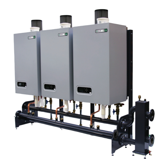
- Page 1 Upsilon Commercial Modular High Efficiency Condensing Boiler UB - 70/110/140 0310 351 Installation and Service Manual Innovation has a name. These instructions should be retained by user.
- Page 2 Version: from sv 4.1 05-2013...
-
Page 3: Table Of Contents
15.3 Conditions for installation and use ....................56 15.4 Exclusions ............................57 15.5 Scope of the warranty ........................57 15.6 Claims ............................57 15.7 Obligations of A.O. Smith Water Heaters ..................57 Annex A Technical specifications ........................58 Annex B System water additives ........................59 Annex C Dimensions ..........................60... -
Page 4: Introduction
Introduction These instructions describe the functioning, installation, use and primary maintenance of A.O.Smith central heating boilers for the United Kingdom and Ireland. Where necessary the different regulations for each country are separately described. These instructions are intended for the use of Gas Safe registered installers or registered Bord Gais installers in connection with the installation and putting into operation of A.O.Smith boilers. - Page 5 20 19 description components figure 1.a heat exchanger 1 (All UB-types) service valves flow/return (in optional boiler connections set) heat exchanger 2 (UB 110 and UB 140) fill and drain valve (in optional boiler connections set) ignition unit safety valve (in optional boiler connections set) fan unit flue connection damper...
- Page 6 description components figure 1.b Air supply (for parallel flue connection) Low velocity header Flue/Air supply (concentric) Safety valve Gas isolation valve Fill and drain valve Service valves flow and return Automatic air vent low velocity header Non-return valve Pocket for temperature sensor T10 Flow/return header Cascade manager Gas line...
-
Page 7: Regulations
The current Electricity at Work Regulation must be complied with and also be in accordance with the relevant and current editions of the British Standards. The Upsilon boiler is a certified appliance and must not be modified or installed in any way contrary to this Installation Manual. Manufacturers instructions must not be taken, in any way, as overriding statutory obligations. - Page 8 Take note of the following when maintenance or adjustments are needed: The boiler must be able to function during these activities; for this reason, the boiler’s supply voltage, gas pressure and water pressure must be maintained. Ensure that there is not a source of potential danger during these activities. Following maintenance or other activities; always check the connections of all parts through which gas flows (using leak-search spray).
-
Page 9: Scope Of Delivery
Scope of delivery The boiler will be delivered ready for use. The delivery package includes the following: • Boiler and housing: • Boiler pump(s); • Cascade control system; • Automatic air vent(s); • Siphon; • Lid ø100 air supply (with screw); • PG cable glands; •... -
Page 10: Description
Upsilon CH-boilers are high-powered wall-mounted gas boilers for instances where a lot of power is required. Cascading the Upsilon CH-boilers provides ample room to connect up to a maximum of 8 boilers and an output capacity of 1.1 MW. The Upsilon-series is structured as follows: - UB 70 Nominal capacity (80/60°C) -
Page 11: Installation And Mounting
The floor has to be flat and level and have sufficient deadweight capacity for the complete (filled) installation. The Upsilon cascade can be mounted in 3 ways: - Wall-mounted in line All boilers alongside one another on the wall Refer to chapter 5.1 and 5.4... -
Page 12: Wall-Mounted In Line
5.1 Wall-mounted in line A . Position the pipe work header against the wall. When using several pipe work headers: couple the pipe work headers and supplied gaskets, M12 (DN65) or M16 (DN100) bolts, spring washers and nuts. Align the pipe work header(s) horizontally using the adjustable feet. -
Page 13: Free-Standing In Line
5.2 Free-standing in line A . Position the pipe work header in the required location. When using several pipe work headers: couple the pipe work headers using the supplied gaskets, M12 (DN65) or M16 (DN100) bolts, spring washers and nuts. Align the pipe work header(s) horizon- tally using the adjustable feet. -
Page 14: Free-Standing Back To Back
5.3 Free-standing back-to-back A. Position the pipe work header in the required location. When using several pipe work headers: couple the pipe work headers with the supplied gaskets, M12 (DN65) or M16 (DN100) bolts, spring washers and nuts. Align the pipe work header(s) horizontally Figure 5.3.a using the adjustable feet. -
Page 15: Connecting The Boiler
5.4 Connecting the boiler A. Remove the remaining packaging part from the bottom of the boiler. Note: this packaging part is provided with boiler parts which are needed for mounting the boiler. Figure 5.4.a B. Cap the connections that are not used on the pipe work headers: Flow and return: ø35mm blind compression fitting (2 items/boiler) Gas: 1 ¼"... -
Page 16: Hydraulic And Gas Line System
Hydraulic and gas pipe line system 6.1 Heating system Install the CH-system in accordance with present legislation. The pipe work headers are available in 2 dimensions, i.e. DN65 and DN100 and are connected to one another by the flange couplings and gaskets, M12 or M16x55 bolts, spring washers and nuts. -
Page 17: Expansion Vessel
Required components that are not supplied by A.O.Smith: The installation pump; - The condensate discharge system. The installation water filter; - Air and dirt separator Gas filter; - Hot water supply Regulation valve; 6.2 Expansion vessel The CH-installation has to be fitted with an expansion vessel. The expansion vessel used has to comply with the water contents of the installation. - Page 18 On installation and during additions or changes at a later stage, A.O.Smith recom- mends to keep a record of the type of water used, its quality at the time, and if ap- plicable, which additives and quantities were added. Parameter Value Water type Potable water...
-
Page 19: Gas Line
The Upsilon boilers can be converted from natural-gas to propane/lpg and from propane/ lpg to natural-gas. When the boiler has to be converted, A.O. Smith provides special kits for this purpose. Special instructions are supplied with the kit. The lpg-gas has to have a propane purity of at least 90%. When the butane-level is greater then 10% the warranty conditions on the heat exchangers are not valid. -
Page 20: Condensate Drain
6.5 Condensate drain All A.O.Smith wall hung gas fired condensing boilers contain a syphonic condensate trap to collect and release condensate. The amount of condensate formed is determind by the type of boilers and the water temperature produced by the boiler. Condensate pipework. - Page 21 Final discharge options. The condensate pipe can only terminate into any one of the five areas as shown in the diagrams on this page. Draining of the condensation water to the external rain guttering is not permitted in view of the danger of freezing. Before putting the boiler into operation fill the syphon with 600 ml of water. A -Condensate from boiler syphon/trap B -Sink with internal overflow C -25mm dia.
-
Page 22: Flue Gas System
Flue gas system The flue gas exhaust system and air supply system consists of: Flue gas pipe; Air supply pipe; Roof or wall terminal. The flue gas exhaust system and air supply system must comply with: United Kingdom: The flue gas outlet and air supply installation must comply with the current regulation requirements. -
Page 23: Parallel Boiler Connection
7.1 Parallel boiler connection The boiler comes as standard with a parallel connection for the flue gas outlet and air supply system. The air supply opening (1) has a diameter of ø100mm. The air supply channel can be connected to it, or, if it involves an “open device” (Drainage category B), an air filter can be connected (recommended). -
Page 24: Connecting The Flue Gas Outlet/Air Supply System
7.3 Connecting the flue gas outlet-/air supply system Upsilon-boilers can be used both in an “open” and in “closed" system. Open: The required combustion air is taken from the immediate environment (boi- ler room). For this purpose, please comply with the applicable boiler room ventilation regulations BS 6644. - Page 25 2m ( 6.6ft ) above a pavement or platform to which people have access ( including ) any balcony or flat roof. The terminal must be protected by a guard of durable material. Contact A.O. Smith for a suitable guard. Where a terminal is fitted below a window which is hinged at the top, and where the hinge axis is horizontal, and the window opens outwards, the terminal shall be 1m below the bottom of the window opening.
- Page 26 The appliance produces a white wisp of condensation (pluming). This wisp of condensation is harmless, but can be unattractive, particularly in the case of outlets in outside walls. At this time there are 2 different ways of connecting the flue gas/air intake system, parallel or concentric.
-
Page 27: Collective Flue Gas Outlet
6.3) it may also be obtained from this area (`open device` Boiler category B). In the case of collective venting of flue gases, the flue gas-venting outlet always has to end up in the open area (outlet area 1). A.O.Smith can supply a collective flue gas outlet system for the Upsilon boiler. Refer to the following chapters with regard to the various possibilities and maximum pipe lengths that can be used. - Page 28 7.5.1 Collective flue gas outlet under-pressure Diameter and venting lengths of the flue gas outlet/air supply: Open system, with under-pressure Dimensions cascade flue Upsilon Open system, underpressure (calculated with thermal draft) Output (P) under atmospheric circumstances. kW at 80/60°C Type UB d = minimum diameter Ø in mm 110 140 h = 2 - 5 h = 5 - 9...
- Page 29 7.5.2 Collective flue gas outlet over-pressure An installation with a collective flue gas outlet over-pressure in combination with individually controlled boilers (e.g. 0-10 V control), where no bus cable 0310289 is connected, is NOT allowed. Diameter and venting lengths of the flue gas outlet/air supply: Open system with over-pressure. Dimensions cascade flue Upsilon Open system, overpressure, parallel Output (P) kW at 80/60°C Type UB d = minimum diameter Ø in mm 70 110 140 h = 2 - 5 h = 6 - 10 h = 11 - 15 h = 16 - 20...
-
Page 30: Condensate Vent Collective Flue Gas System
7.6 Condensate vent collective flue gas outlet system Flue gases condensate inside the outlet system. Anticipate approx. 1 litre of con- densate per m3 of natural gas spent on heating. The resulting condensate has to be drained. Therefore, collective flue gas outlet systems have to be fitted with a condensate drai- nage facility. -
Page 31: Electrical Connections
All connections have to be made to the terminal block. The boiler has 4 terminals for all electrical connections. 1. High voltage supply (230V) 2. Voltage free switches (230V relays) 3. Low voltage sensors 4. Communication bus for cascaded Upsilon boilers Front view Side view On/Off Error... - Page 32 1. High voltage supply: 16 Connections Position Connection Application Max. On/Off Error General 230V~ 230V Open- signal purpose Therm On/Off 1, 2, 3 Live Neutral Earth Power for boiler. Power cable not supplied 13,5* 230V 230V~ 230V Heat 0-10Volt LWCO demand signal 4, 5, 6...
-
Page 33: External Controls
2 cables etc.) and is fitted with 2 IP67 tulles. A maximum of 8 boilers can be connected to the system. 8.1 External controls NOTE: - T10 must be connected - T4 is adviced to connect. The Upsilon boiler provides in many possibilities to operate the boilers from external controls. Only 1 type of control can be connected. Connections of the external control must be done in the master boiler (address 01) on terminal 3 and appropriate connec- tions. Below you will find a description of the possibilities and parameter adjustments to take account of. - Page 34 At a heat demand of the 0-10 Volt controller a signal is sent out and varies from 0-10 On/Off Volt. This signal is translated by the Upsilon boiler to a set value (desired flow water General temperature or load) which is send via the data bus to the boiler(s). Depending on the...
-
Page 35: Wiring Diagram
8.2 Wiring diagram T1a (HEX4) 6,3A T 6,3A T 20 10 20 10 6,3A T 6,3A T 10 1 10 1 10 1 18 9 18 9 18 9 figure 8.1.a... - Page 36 Ignition and Gasvalve Ignition and 6, 10 Gasvalve 8, 12 Cable loom 230V See A23 burner B 10, 14 Cable loom bus Burner X8-A X8-B Bus1 25 0310383(S) Flat cable MMI Bus1 26 0310289 Communication bus cable Upsilon Bus1 Bus1...
-
Page 37: Boiler Control
Boiler control The boiler has a control unit. This control takes care of most of the manual settings but also provides numerous settings to adjust the control exactly to the installation and user requirements. Display The LCD screen is backlit. The light is activated by pushing one of the buttons. There are 3 light colours available. -
Page 38: Operational Status
9.1 Operational status - Standby Standby. Boiler is ready for operation. - Vent.Phase Ventilation stage Standby - Ignition phase Ignition stage - Burner lit CH Burner active for heating - Burner lit DHW Burner active for hot water - CH T > Tset Burner off on account of too high flow temperature CH - Overrun CH Overrun time pump over CH - Overrun DHW... -
Page 39: Commissioning
9.3 Commissioning Turn the electrical supply on (heating system does not have to be filled); During start-up, a blue screen is displayed: -- NC -- NC Power Up (= start-up screen) Power Up Please wait (under certain circumstances) Address Then you see: Address (= allocation of boiler address) In the case of a cascade installation: Select the correct address and press OK... - Page 40 (P in bar). 1.65 bar For Upsilon boilers in cascade For Upsilon boilers in cascade, the bus communication cables between the boilers must be connected (see section electrical connections). The master-boiler (address 01) should be set to how many boilers are actually connected.
-
Page 41: Basic Settings
9.4 Setting the maximum flow water temperature with On/Off-control P101 = 0 Setting the maximum flow water temperature with connected outdoor sensor T4 (starting with illuminated display): 1. Press the right arrow button: The display shows: Basic Settings; Basic Settings 2. Press the OK button; 3. Press the right arrow button until CH temp: The display shows: CH temp 85°C;... - Page 42 9.5 Filling the heating system When all boilers have been electrically commissioned as described above, then the heating system can be filled. Each boiler is fitted with a filling and drain valve. The filling hose from the water tap is then connected to it. Fill the heating system only with drinking water. Refer to the Water Quality chapter for quality requirements of the filling water.
- Page 43 Behaviour of connected external controls 8:00 When using an OpenTherm or 0-10Volt control and a clock 12:00 night program is selected, the clock program of the Upsilon will 17:00 be ignored. 19:00 night When an on/off control is connected and the thermostat is switched on manually before the pre-setted switch-on...
- Page 44 Menu structure at Setting level With the illumination switched off, first press on one of the buttons to switch the illumination on and then continue with the setting. Having pressed the last button, the green illumination will switch off after 2 min. From the standard read-out, keep both arrow buttons pushed down simultaneously for 2 sec. The screen colour will change from blue to green. With the arrow buttons you can go through the different chapters. Good Operational status Press OK to select or to confirm a change.
-
Page 45: Parameters
11 Parameters For operation and menu overview, refer to chapter Boiler control and Basic settings. Basic settings Basic settings factory PARA Description Range setting CH prog CH-program on/off DHW prog DHW-program on/off Pump prg Pump program (frost protection) on/off Timerpr CH Clock program CH on/off Timerp DHW Clock program DHW... - Page 46 Param Mode Parameter chapter factory PARA Description Range setting Cascade param. Cascade parameters P100 Domestic hot water facility NOTE: 0: no DHW Option 6 and 8 not for Low Temerature 1: Solo boiler with 3-way valve systems, unless separately controlled 2: n.a. 3: Solo boiler with cylinder loading pump P4 and 3-way valve 4: n.a.
- Page 47 Boiler param Boiler parameters P100 Domestic hot water facility (visible when boiler address is 2 - 8) 0: no DHW 1: Solo boiler with 3-way valve 2: n.a. 3: Solo boiler with cylinder loading pump P4 and 3-way valve 4: n.a. P102 Cascade flue gas system 0: Flue gas system individual or collective under pressure...
- Page 48 Error Errors The last 10 errors with data will be stored. Error burner A Choose burner A or B using arrow buttons. Exchanger symbol will show: A or B Select other error number (02-10) with arrow buttons Error 01 Every error contains the following info (Press + button for forward, - button for backward) Code Exxscxx Date Time...
-
Page 49: Activate Factory Settings
11.1 Activate factory settings Do the following to reactivate factory settings (any changed settings will be lost): Activating the factory settings from user level only: From the standard blue screen display: 1. Select using the right arrow button: Basic settings; 2. Press the OK button; Restore 3. Press the right arrow button until: Restore Defaults 4. -
Page 50: Inspection And Maintenance
Inspection and maintenance tasks have to be carried out in accordance with the main- tenance instructions at all times. Some tasks are described in these maintenance instruc- tions. For complete inspection and maintenance instructions, please contact A.O. Smith. When carrying out maintenance on the boiler, the gas tap has to be closed and secured against opening. - Page 51 13.2.1 Emission check In order to be able to check on the boiler’s emission during its years of operation, it is recommended to measure the maximum air displacement of the boiler on commissioning. This value may be different for each boiler type. This measuring is only worthwhile if the value is known on commissioning.
- Page 52 5,1% and 7,0% CO percentage at low load between 7,7% and 8,8% 9,1% and 10,3% Contact A.O. Smith when the measured values is outside this range. adjusting screw figure 13.2.2.b End of measuring: Press the – button until off is displayed (keep pushed down). This ends the procedure for burner A.
-
Page 53: Maintenance Activities
13.3 Maintenance activities The following actions have to be taken in order to be able to carry out maintenance: Switch the device off using the mains switch, close the gas tap; Refer to figure 13.3.a: Unscrew the 4 screws of quick-locks A, B, C and D Open the 4 quick-locks A, B, C and D and remove the housing (= air box) from the front. - Page 54 Remove the burner cassette (18) from the ventilator unit; Check the burner cassette for wear and tear, pollution and any breakages. Clean the burner cassette with a soft brush and vacuum cleaner. In the case of breakages, always replace the complete burner cassette (18); Replace the gasket (17) between the burner (18) and upper casing (15) ;...
- Page 55 Ignition electrode Replace the ignition electrode when necessary, but certainly every 4 years. This can be checked by reading out the ionisation current. The minimum ionisation cur- rent has be greater than 2,0 µA at full capacity. To read out the ionisation current follow the instructions: From the standard blue screen display: 1.
-
Page 56: Counter Running Hours
Syphon (refer to fig. 13.3.f) Place a collector (i.e. a bucket) under the syphon to collect the dirty and aggressive condensate water. Wear protective clothing like latex gloves and safety glasses. Dismantle the syphon by unscrewing the syphon cup (H). Check the syphon cup (H), siphon adapter (G) and syphon pipe (I) for pollution. Clean these parts by rinsing them with water. Re-grease the O-rings with acid-free O-ring grease to facilitate easy assembly. If the syphon shows any leakage, the whole siphon has to be replaced: Take the device back into operation and conduct a flue gas analysis (refer to chapter Check O... -
Page 57: Error Report
Error report On the display, errors found are shown in the form of a message or blocking on a blue screen or an error on a red screen. Blocking This is a temporary error that will sort itself out, or it will block the boiler after several attempts (error)(Except: Bx01sc01 = reset) Error Error implies a blocking of the boiler and can only be solved by a... -
Page 58: Warranty Conditions
Product Registration Form. Registering the boiler gives the owner of the boiler supplied by A.O. Smith Water Heaters the right to the warranty set out below, which defines the commitments of A.O. Smith Water Heaters to the owner. -
Page 59: Exclusions
A.O. Smith Water Heaters parts for spare parts or as a repair part. 15.5 Scope of the warranty The obligations of A.O. Smith Water Heaters pursuant to the specified warranty are limi- ted to free delivery from the warehouse of the replacement assemblies, parts or central heating boiler, respectively. -
Page 60: Annex A Technical Specifications
Annex A Technical specifications Technical specifications Natural gas G20 Upsilon Boiler type UB 70 UB 110 UB 140 Type heat exchanger HEX4 HEX4 HEX4 HEX2 HEX4 Input Hs CH 68,5 107,9 136,4 Input Hi CH 61,8 97,3 Efficiency class according BED Rendement volgens EN677 / EN15417 (36/30°C deellast, onderw.) -
Page 61: Annex B System Water Additives
Annex B System water additives When the filling water requirements as referred to in chapter Water Quality have been met, certain additives are allo- wed for the below mentioned applications and related dosage. Warranty on A.O.Smith delivered installation products expires, if these additives and concentrations are not used in accordance with this annex. Additive type Supplier and specifications Max. - Page 62 Dimensions ø150 ø100 ø100 Individual flue: min. 400mm Collective flue: depen- dant from selected flue sytem. Please contact the supplier Upsilon Boiler type UB 70 UB 110 UB 140 Concentric flue system 100 / 150 100 / 150 100 / 150 Parallel flue system...
- Page 63 2 Upsilon boilers free-standing in line 3 Upsilon boilers free-standing back-to-back 1430 1430 1000 4 Upsilon boilers free-standing in line 2830 8 Upsilon boilers free-standing in line 5630...
- Page 64 Dimensions flue connections 1430 1000...
- Page 65 Dimensions low velocity header DN65 until 452kW Dimensions main header G1/2” DN65 / DN100 G3/8” DN65 G1” DN65 DN65 L 2/4 places = 1398mm (DN65/DN100) L 3/6 places = 2098mm (DN65/DN100) DN65 Dimensions low velocity header DN100 until 960kW Dimensions bend DN65 and DN100 G1/2”...
- Page 66 Upsilon 1 boiler, wall hung Upsilon 2 boilers, wall hung, max.200kW 3/8” 1/2” Upsilon 1 boiler, free-standing Upsilon 2 boilers, free-standing, max. 200kW 1/2” wall hung free standing Number of Upsilon‐boilers (UB 70, UB 110, UB 140) Necessary articles: 0310265 L‐shape frame for back to back alignment 0310266 I‐shape frame for line alignment 0310267 Boiler frame 0310335 Low velocity header for 1 or 2 boilers (max. 200kW) 0310286 Boiler connection set for single boiler 0310289 Bus communication cable 0310290 Common flow sensor 10kOhm T3/T10...
-
Page 67: Annex D Declaration Of Conformity
Annex D Declaration of conformity CE DECLARATION OF CONFORMITY Hereby declares A.O. Smith Water Products Company B.V. that, the condensing boiler types: Upsilon UB 70 UB 110 UB 140 are in conformity with the provisions of the following EC Directives, including all amendments, and with national legislation implementing these directives:... - Page 68 A.O. Smith UK, Unit B8 Amstrong Mall, Southwood Business Park, Farnborough, Hampshire GU14 0NR www.aosmith.co.uk “A.O. Smith Water Heaters” is a trading name of Advance Services (Sales) Ltd. Reg.