Table of Contents
Advertisement
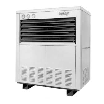
Built tough with maximum efficiency
NATURAL GAS-FIRED COMMERCIAL CROSS FLOW COPPER BOILERS
FOR HYDRONIC HEATING AND HOT WATER SUPPLY
WITH ELECTRONIC INTERMITTENT PILOT IGNITION AND
• INSTALLATION • OPERATION • MAINTENANCE • LIMITED WARRANTY
WARNING: If the information in this manual
is not followed exactly, a fire or explosion may
result causing property damage, personal
injury or loss of life.
— Do not store or use gasoline or other
flammable vapors and liquids in the
vicinity of this or any other appliance.
— WHAT TO DO IF YOU SMELL GAS
·
Do not try to light any appliance.
·
Do not touch any electrical switch;
do not use any phone in your
building.
·
Immediately call your gas supplier
from a neighbor's phone. Follow
the gas supplier's instructions.
·
If you cannot reach your gas
supplier, call the fire department.
— Installation and service must be
performed by a qualified installer,
service agency or the gas supplier.
PRINTED IN U.S.A. 2221 0302
MODELS DB/DW-720-1810
TM
PLACE THESE INSTRUCTIONS ADJACENT TO BOILER AND
NOTIFY OWNER TO KEEP FOR FUTURE REFERENCE.
1
INSTALLATIONS
TEXT PRINTED OR OUTLINED IN RED CONTAINS
INFORMATION RELATIVE TO YOUR SAFETY. PLEASE
READ THOROUGHLY BEFORE INSTALLING AND
USING THIS APPLIANCE.
A DIVISION OF A.O.SMITH CORPORATION
EL PASO, TX McBEE, SC RENTON, WA
STRATFORD, ONTARIO
VELDHOVEN, THE NETHERLANDS
SUPERSEDES PART NO. 200311-000 REV. 4 & 210265-000 REV. 0
CAUTION
www.hotwater.com
PART NO. 211680-000 REV. 00
Advertisement
Table of Contents

Related Manuals for A.O. Smith DB/DW-720-1810


Summary of Contents for A.O. Smith DB/DW-720-1810
- Page 1 PLACE THESE INSTRUCTIONS ADJACENT TO BOILER AND PRINTED IN U.S.A. 2221 0302 MODELS DB/DW-720-1810 INSTALLATIONS TEXT PRINTED OR OUTLINED IN RED CONTAINS INFORMATION RELATIVE TO YOUR SAFETY. PLEASE READ THOROUGHLY BEFORE INSTALLING AND USING THIS APPLIANCE.
-
Page 2: Table Of Contents
Replacement parts may be ordered through A. O. Smith dealers, authorized servicers or distributors. Refer to the Yellow Pages for where to call or contact (in United States) the A.O. Smith Water Products Company, 5621 West 115th Street, Alsip, IL 60803, 1-800-433-2545 or (in Canada) A.O. -
Page 3: Rough-In Dimensions/Capacities
CAUTION Label all wires prior to disconnection when servicing controls. Wiring errors can cause improper and dangerous operation. "Verify proper operation after servicing." ROUGH-IN DIMENSIONS/ CAPACITIES INSTALLATION CLEARANCES These boilers are approved for installation on combustible flooring in an alcove with minimum clearance to combustibles See chart below. - Page 4 Your Dura-Max boiler is not designed to operate with a boiler inlet water temperature of less than 100°F (38°C). Colder inlet water temperatures will result in significant condensation developing on the heat exchanger. This situation can cause a corrosive environment for the heat exchanger, burners and venting resulting in premature damage, which could result in serious personal injury or death.
-
Page 5: Features
FEATURES IMPORTANT Only qualified personnel shall perform the initial firing of the heater. At this time the user should not hesitate to ask the individual any questions regarding the operation and maintenance of the unit. Lighting and Operating instructions are included at the rear of this manual. -
Page 6: Automatic Reset High Temperature Control
AUTOMATIC RESET HIGH TEMPERATURE LIMIT CONTROL CAUTION LIMIT CONTROLS ARE NOT TO BE USED AS THERMOSTATS. ALL MODELS - This limit is a safety device wired in series with the ignition system. Set the limit control dial to a minimum of 10°F (6°C) above the maximum designed system temperature. -
Page 7: Installation Instructions
INSTALLATION INSTRUCTIONS REQUIRED ABILITY INSTALLATION OR SERVICE OF THIS BOILER REQUIRES ABILITY EQUIVALENT TO THAT OF A LICENSED TRADESMAN IN THE FIELD INVOLVED. PLUMBING, AIR SUPPLY, VENTING, GAS SUPPLY AND ELECTRICAL WORK ARE REQUIRED. WARNING THE INLET/OUTLET WATER MANIFOLD ON YOUR A. O. SMITH UNIT INCORPORATES AN "O RING"... -
Page 8: Venting The Boiler
If the confined space is within a building of tight construction, air for combustion, ventilation, and draft hood dilution must be obtained from outdoors. When directly communicating with the outdoors or communicating with the outdoors through vertical ducts, two permanent openings, located in the aforementioned manner, shall be provided. -
Page 9: Gas Connections
WARNING FAILURE TO CORRECT BACK DRAFTS MAY CAUSE AIR CONTAMINATION AND UNSAFE CONDITIONS. Vent connectors serving appliances vented by natural draft shall not be connected into any portion of mechanical draft systems operating under positive pressure. CONNECTING BOILER TO A COMMON VENT Do not connect the boiler to a common vent or chimney with solid fuel burning equipment. -
Page 10: Purging
PURGING Gas line purging is required with new piping or systems in which air has entered. CAUTION PURGING SHOULD BE PERFORMED BY PERSONS EXPERIENCED IN THIS TYPE OF GAS SERVICE TO AVOID RISK OF FIRE OR EXPLOSION. PURGE DISCHARGE MUST NOT ENTER CONFINED AREAS OR SPACES WHERE IGNITION CAN OCCUR. -
Page 11: High Altitude Installations
Applications of the gravity factor converts the figures given in table 1 to capacities with another gas of different specific gravity. Such application is accomplished by multiplying the capacities given in table 1 by the multipliers shown in table 5. To determine the size of each section of gas piping in a system within the range of table 4 proceed as follows: •... -
Page 12: Servicing Wiring And/Or Control
IF ANY OF THE ORIGINAL WIRE, AS SUPPLIED WITH THE APPLIANCE, MUST BE REPLACED, IT MUST BE REPLACED WITH TYPE 105°C WIRE OR ITS EQUIVALENT, EXCEPT FOR THE FLAME SENSOR AND IGNITION CABLE WHICH ARE 250°C. SERVICING WIRING AND/OR CONTROL CAUTION Label all wires prior to disconnection when servicing controls. -
Page 13: Safety Flow Switch
The flow switch shall be mounted in the top opening of the reducing tee and provide adequate paddle length in the flow stream. For example in a 2" pipe installation use a 2" x 2" x 1" reducing tee. For 2"... -
Page 14: Low Water Cutoff
Thereafter, during the heating season, lubricate the three oil cups at least once every four months. Combination heating/cooling systems or water heating (Cer-temp) systems should be lubricated every four months year-round. Use 2 or 3 teaspoonfuls in bearing oil cups, fig. 9, and 10 or 12 drops in the motor oil cups. -
Page 15: Installation As Boiler Replacement
A system bypass should be installed as shown in fig. 10 to prevent boiler circulation starvation when the system zones call for reduced flow. This bypass may also be used with multiple boilers manifolded for reverse-return flow. The system bypass would be installed from boiler outlet to suction side of pump. - Page 16 NOTES: 1. BUILDING TEMPERATURE CONTROLS SUPPLY ELECTRIC POWER TO BUILDING CIRCULATOR. 2. MAIN FLOW SWITCH PROVES MAIN WATER FLOW BEFORE ENERGIZING, SEQUENCING AND RESETTING CONTROLS. 3. OUTDOOR THERMOSTAT REQUIRED IF BUILDING CONTROLS DO NOT PROVIDE AUTOMATIC SHUT-DOWN OF RESET CONTROLS DURING WARM WEATHER.
-
Page 17: Linear-Temp Space Heating Applications
The fast response of A.O. Smith boilers eliminates any need to maintain boiler temperature when the system is satisfied. Wiring should always prevent firing of boiler(s) when there is no water flow in the mains. - Page 18 generator type boilers establish temperature rises. The deciding factor in choice of boiler temperature rise relates to the boiler inlet temperature. Boiler outlet, minus system temperature drop, is boiler inlet temperature. THE BOILER TEMPERATURE RISE SHOULD NOT RAISE THE OUTLET TEMPERATURE UP TO THE MAXIMUM 250°F (115°C) SETTING OF THE LIMIT CONTROL.
- Page 19 TABLE 8. SUGGESTED ITEMS FOR INSTALLATION SHORT PIPE NIPPLE AND PAIR OF BOILER LOOP TEES IN PIPING BETWEEN SYSTEM SUPPLY AND RETURN - ONE SET PER EACH BOILER BOILER PIPE LOOP (See Piping Sizing Data Table 3.) BOILER CIRCULATING PUMP (See Piping Sizing Data Table 3.) THERMOMETER PRESSURE GAUGE LOW WATER CUT-OFF (If Required By Local Code.)
- Page 20 USE ONY TYPE 105°C THERMOPLASTIC OR ITS EQUIVALENT IF ANY OF THE ORIGINAL WIRES AS SUPPLIED MUST BE REPLACED. BOILER CONVENTIONAL SYSTEM FIGURE 15 USE ONY TYPE 105°C THERMOPLASTIC OR ITS EQUIVALENT IF ANY OF THE ORIGINAL WIRES AS SUPPLIED MUST BE REPLACED. ONE BOILER LINEAR-TEMP SYSTEM FIGURE 16...
-
Page 21: Wiring And Schematic Diagrams
DURA-MAX - SINGLE STAGE FIRING - UNITED STATES MODELS WITH PUMP. 120 VOLT SYSTEM CONTROLLER DURA-MAX - PUMP MOUNT - SINGLE STAGE - SCHEMATIC DIAGRAM... - Page 22 DURA-MAX - DUAL STAGE FIRING - UNITED STATES MODELS WITH PUMP. 120 VOLT SYSTEM CONTROLLER DURA-MAX - PUMP MOUNT - DUAL STAGE - SCHEMATIC DIAGRAM...
- Page 23 DURA-MAX - MODULATED FIRING - UNITED STATES MODELS WITH PUMP. 120 VOLT SYSTEM CONTROLLER DURA-MAX - PUMP MOUNTED - MODULATING - SCHEMATIC DIAGRAM...
- Page 24 DURA-MAX - SINGLE STAGE FIRING - UNITED STATES & CANADIAN MODELS WITHOUT PUMP. 120 VOLT SYSTEM CONTROLLER DURA-MAX - SINGLE STAGE FIRING - SCHEMATIC DIAGRAM...
- Page 25 DURA-MAX - DUAL STAGE FIRING - UNITED STATES & CANADIAN MODELS WITHOUT PUMP. 120 VOLT SYSTEM CONTROLLER DURA-MAX - DUAL STAGE FIRING - SCHEMATIC DIAGRAM...
- Page 26 DURA-MAX - MODULATED FIRING - UNITED STATES & CANADIAN MODELS WITHOUT PUMP. 120 VOLT SYSTEM CONTROLLER DURA-MAX - MODULATED FIRING - SCHEMATIC DIAGRAM...
-
Page 27: Hot Water Supply Applications
HOT WATER SUPPLY APPLICATIONS Cer-Temp 80 Recovery Systems WATER LINE CONNECTIONS This section provides detailed installation diagrams for typical methods of application for the unit using a Cer-Temp 80 Recovery System (for one temperature water). This equipment must be protected against loss of water or loss of water flow by the installation of a safety flow switch in the outlet piping from the boiler. - Page 28 ONE DURA-MAX (MODEL DW) COMMERCIAL BOILER WITH HORIZONTAL TANK TO PREVENT CONDENSATION THE MINIMUM BOILER INLET TEMPERATURE IS 100°F (38°C) IMPORTANT SAFETY FLOW SWITCH AS SHOWN TO PROTECT THE BOILER IN CASE OF WATER SERVICE INTERRUPTION OR CIRCULATOR FAILURE. INSTALL IN ACCORDANCE WITH ALL LOCAL CODES. SEE PAGE 31 FOR ADDITIONAL PIPING INFORMATION.
- Page 29 TWO DURA-MAX (MODEL DW) HOT WATER SUPPLY BOILERS WITH VERTICAL TANK TO PREVENT CONDENSATION THE MINIMUM BOILER INLET TEMPERATURE IS 100°F (38°C) Guide To Pipe and Pump Sizing Two (2) Boiler Systems Common Manifold Pipe Boiler Pipe Size Model Size "A" (Min.) "B" (Min.) and Pump 720, 840 2-1/2"...
- Page 30 TWO DURA-MAX (MODEL DW) HOT WATER SUPPLY BOILERS WITH HORIZONTAL TANK TO PREVENT CONDENSATION THE MINIMUM BOILER INLET TEMPERATURE IS 100°F (38°C) SEE PAGE 31 FOR ADDITIONAL PIPING INFORMATION. CAUTION THE INSTALLATION OF SAFETY FLOW SWITCHES AS SHOWN IS REQUIRED TO PROTECT THE BOILER IN CASE OF WATER SERVICE INTERRUPTION OR CIRCULATOR FAILURE.
- Page 31 NOTE: METRIC SIZING IS FOR COMPARISON ONLY - ALL UNITS CONSTRUCTED WITH TANK FITTING MEASURED IN INCHES. A.O. SMITH TJV-120M & TJV-200M TANKS WITH: PART NO. 170354 FOR TWO TANK MANIFOLD KIT PART NO. 170355 FOR THREE TANK MANIFOLD KIT TANK TEMPERATURE CONTROL SHOULD BE LOCATED APPROXIMATELY 6"...
-
Page 32: Start-Up And Operating Instructions
TWO HORIZONTAL TANK INSTALLATION THREE HORIZONTAL TANK INSTALLATION START-UP AND OPERATING INSTRUCTIONS WARNING After placing boiler into operation, the ignition system safety shutoff device must be tested by the following test method. 1. Reset Manual High Temperature Safety Limit Control (High Limit) to the lowest setting. -
Page 33: Lighting And Operating Instructions
LIGHTING AND OPERATING INSTRUCTIONS FOR YOUR SAFETY READ BEFORE OPERATING "WARNING: IF YOU DO NOT FOLLOW THESE INSTRUCTIONS EXACTLY, A FIRE OR EXPLOSION MAY RESULT CAUSING PROPERTY DAMAGE, PERSONAL INJURY OR LOSS OF LIFE." WARNING: HOT WATER CAN PRODUCE 3rd DEGREE BURNS IN 6 SECONDS AT 140° F. (60° C). IN CASE OF POWER FAILURE DO NOT ATTEMPT TO OPERATE BOILER. -
Page 34: Internal Contaminants
INTERNAL CONTAMINANTS The system must be internally cleaned and flushed after a new or replacement unit has been installed to remove contaminants that may have accumulated during installation. This is doubly important when a replacement unit is installed into an existing system where Stop Leak or other boiler additives have been used. -
Page 35: Main Burner
1. Remove main burners from unit. 2. Check that burner venturi and ports are free of foreign matter. 3. Clean burners with bristle brush and/or vacuum cleaner 3/4" DO NOT distort burner ports or pilot location. 4. Reinstall burners in unit. Making sure front and rear of burners are installed correctly in burner support brackets. - Page 36 CHECKING HONEYWELL S8600H OR S8610M (NAT. GAS) INTERMITTENT IGNITION CONTROLS Replace ignition module Turn on gas supply. Turn on power supply. Securely connect cable and/or ground wire. Replace cable and/or ground wire. Carefully bend down- wards top of ground strap to achieve 1/8"...
- Page 37 SPARK AT PILOT BURNER BUT PILOT WILL NOT LIGHT Attach wires firmly. Replace gas valve. Turn on power supply. Securely connect cable and/or ground wire. Replace cable and/or ground wire. Carefully bend down- wards top of ground strap to achieve 1/8"...
- Page 38 PILOT BURNER LIGHTS BUT MAIN BURNER DOES NOT LIGHT Correct the situation by consulting the installation or user’s manual on how to adjust pilot flame. Replace ignition module. Is voltage (24 Vac) across terminals MV and MV/PV? Attach wires Are the wires securely attached to the main firmly.
-
Page 39: General Maintenance
GENERAL MAINTENANCE These boilers are designed to give many years of efficient and satisfactory service when properly operated and maintained. To assure continued good performance, recommendations are made. The area around the unit should be kept clean and free from lint and debris. -
Page 40: Deliming Solvents
LIME may be obtained from your dealer, distributor or the • A.O. Smith Water Products Company, Part No. 4763 (1 gal. [4 L]) packed 4 gallons (16 L) per case, Part No. 4813 (5 gal. [20 L]) single container. -
Page 41: Limited Warranty
A. O. Smith Corporation, the warrantor, extends the following LIMITED WARRANTY to the owner of this hydronic boiler: If within TEN years after initial installation of the boiler, the heat exchanger shall prove upon examination by the warrantor to be defective in material or workmanship, the warrantor, at his option will exchange or repair such part or portion. - Page 44 REPLACEMENT PARTS 5621 W. 115TH STREET, ALSIP, IL 60803 PHONE: 800-433-2545 FAX: 800-433-2515 www.hotwater.com E-Mail: parts@hotwater.com...