Table of Contents
Advertisement
Quick Links
Advertisement
Table of Contents

Related Manuals for Lenovo Storage V7000


Summary of Contents for Lenovo Storage V7000
-
Page 1: Quick Installation Guide
Lenovo Storage V7000 Quick Installation Guide Machine Types: 6538... - Page 2 • The information in the Environmental Notices and User Guide First Edition (October 2016) © Copyright Lenovo 2016. LIMITED AND RESTRICTED RIGHTS NOTICE: If data or software is delivered pursuant to a General Services Administration “GSA” contract, use, reproduction, or disclosure is subject to restrictions set forth in Contract No.
-
Page 3: Table Of Contents
Appendix A. Accessibility features for Lenovo Storage V series library and related Lenovo Storage V7000 ..35 publications ....xiii Related websites . - Page 4 Lenovo Storage V7000 Quick Installation Guide...
-
Page 5: Figures
Expansion enclosure support rails on Lenovo connected to 10 Gbps iSCSI-FCoE 4-port Storage V7000 ... . . host interface adapters ..Control enclosure support rails .. - Page 6 Lenovo Storage V7000 Quick Installation Guide...
-
Page 7: Tables
....xiii Selecting bracket pins for your rack ..Lenovo Storage V Series library ..xiii Selecting bracket pins for your rack .. -
Page 8: Safety And Environmental Notices
Safety and environmental notices ® Review the safety notices, environmental notices, and electronic emission notices for Lenovo Storage V7000 before you install and use the product. Suitability for telecommunication environment: This product is not intended to connect directly or indirectly by any means whatsoever to interfaces of public telecommunications networks. - Page 9 CAUTION: • Do not install a unit in a rack where the internal rack ambient temperatures will exceed the manufacturer's recommended ambient temperature for all your rack-mounted devices. • Do not install a unit in a rack where the air flow is compromised. Ensure that air flow is not blocked or reduced on any side, front, or back of a unit used for air flow through the unit.
- Page 10 Electrical voltage and current from power, telephone, and communication cables are hazardous. To avoid a shock hazard: • If Lenovo supplied a power cord(s), connect power to this unit only with the Lenovo provided power cord. Do not use the Lenovo provided power cord for any other product.
- Page 11 • Do not connect or disconnect any cables or perform installation, maintenance, or reconfiguration of this product during an electrical storm. • The product might be equipped with multiple power cords. To remove all hazardous voltages, disconnect all power cords. •...
- Page 12 DANGER Observe the following precautions when working on or around your IT rack system: • Heavy equipmentpersonal injury or equipment damage might result if mishandled. • Always lower the leveling pads on the rack cabinet. • Always install stabilizer brackets on the rack cabinet. •...
-
Page 13: Special Caution And Safety Notices
Special caution and safety notices This information describes special safety notices that apply to the Lenovo Storage V7000 system. These notices are in addition to the standard safety notices supplied and address specific issues relevant to the equipment provided. -
Page 14: About This Guide
(This action removes static electricity from the package and from your body.) • Remove the device from its package and install it directly into your Lenovo Storage V7000 system, without putting it down. If it is necessary to put the device down, place it onto its static-protective bag. (If your device is an adapter, place it component-side up.) Do not place the device onto the cover of the... -
Page 15: Lenovo Storage V Series Library And Related Publications
Support for Lenovo Storage V7000 http://support.lenovo.com/p/storage/v7000 Each of the PDF publications in the Table 2 “Lenovo Storage V Series library” on page xiii is also available by clicking the corresponding “Link”: Table 2. Lenovo Storage V Series library Title... -
Page 16: Related Websites
Table 3 “Lenovo documentation and related websites” on page xiv lists websites that provide publications and other information about the Lenovo Storage V Series or related products or technologies. The Lenovo Press publications provide positioning and value guidance, installation and implementation experiences, solution scenarios, and step-by-step procedures for various products. -
Page 17: How To Get Information, Help, And Technical Assistance
China, you can call 8008106677-2 or 4008106678-2 for help and service. Software option Identify the Lenovo Storage V7000 product as your product and supply your customer number as proof of purchase. The customer number is a 7-digit number (0000000 to 9999999) assigned by Lenovo when the product is purchased. -
Page 19: Chapter 1. Before You Begin The Installation
2. The steps in Chapter 2 “Installing the Lenovo Storage V7000 hardware” on page 11 involve installing the hardware and attaching the data cables and power cords. -
Page 20: Storage V7000
Be familiar with the following information • See “Caution notices for the Lenovo Storage V series” on page vi and “Danger notices for Lenovo Storage V7000” on page viii for a summary of the situations that can be potentially hazardous to you. Before installing, read and understand the following caution and danger statements. - Page 21 Electrical voltage and current from power, telephone, and communication cables are hazardous. To avoid a shock hazard: – If Lenovo supplied a power cord(s), connect power to this unit only with the Lenovo provided power cord. Do not use the Lenovo provided power cord for any other product.
-
Page 22: Reviewing Your Packing Slip
• Four-port 8 Gbps Fibre Channel host interface adapter with two small form-factor pluggable (SFP) transceivers installed • Fibre Channel cables • SAS cables • Four-port 10 Gbps iSCSI / FCoE host interface adapter • Compression accelerator • Drives • Power cords for connection to wall sockets Lenovo Storage V7000 Quick Installation Guide... -
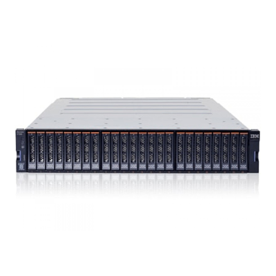
Page 23: Identify The Hardware Components
Lenovo Storage V7000 systems. Control enclosure components Figure 1 “Rear view of a Lenovo Storage V7000 control enclosure” on page 5 shows the rear view of a control enclosure and identifies the location of the power supply units and node canisters. -
Page 24: Control Enclosure Support Rails Of A Lenovo
Figure 3. Control enclosure support rails of a Lenovo Storage V7000 system Expansion enclosure components Figure 4 “Rear view of a Lenovo Storage V7000 expansion enclosure” on page 7 shows the location of the power supply units and expansion canisters. -
Page 25: Sas Ports And Leds In Rear View Of A Lenovo
Figure 4. Rear view of a Lenovo Storage V7000 expansion enclosure Figure 5 “SAS ports and LEDs in rear view of a Lenovo Storage V7000 expansion canister” on page 7 shows the LEDs and SAS port locations from the rear view of an expansion canister. -
Page 26: Verify Environmental Requirements
The environmental and electrical requirements for the physical site must be met to ensure that your system works reliably. Before installing a Lenovo Storage V7000 system, you must verify that adequate space in a suitable rack is available. You must also ensure that the requirements for power and environmental conditions are met. - Page 27 If you are installing a control enclosure plus one or more expansion enclosures, follow these guidelines. • A Lenovo Storage V7000 system can support up to 1056 drives installed into control and expansion enclosures. Each enclosure requires 2U of rack space.
- Page 28 Lenovo Storage V7000 Quick Installation Guide...
-
Page 29: Chapter 2. Installing The Lenovo Storage V7000 Hardware
You are now ready to begin installing the hardware components and connecting the data cables and power cords. Installing support rails for the Lenovo Storage V7000 control enclosure Before you install the control enclosure, you must first install the support rails for it. -
Page 30: Installing The Rail Spring
Working at the front of the rack cabinet, identify the two standard rack units (2U) of space in the rack into which you want to install the support rails. Figure 9 “Hole locations in the front of the rack” on page 13 shows two rack units with the front mounting holes identified. Lenovo Storage V7000 Quick Installation Guide... -
Page 31: Selecting Bracket Pins For Your Rack
Unscrew the medium pins and replace with the large pins supplied with the rails. Step 5. At each end of the rail, grasp the tab and pull firmly to open the hinge bracket.(See Figure 10 “Opening the hinge brackets” on page 14.) Chapter 2 Installing the Lenovo Storage V7000 hardware... -
Page 32: Opening The Hinge Brackets
Step 10. Close the front hinge bracket to secure the rail to the rack cabinet flange.(See Figure 11 “Closing the hinge brackets” on page 14.) Step 11. Secure the rear of the rail to the rear rack flange with an M5 screw. Lenovo Storage V7000 Quick Installation Guide... -
Page 33: Installing Support Rails For Lenovo Storage V7000 Expansion Enclosures
Step 12. Repeat the steps to secure the opposite rail to the rack cabinet. Step 13. Repeat the procedure to install rails for each additional control enclosure. Installing support rails for Lenovo Storage V7000 expansion enclosures Before installing expansion enclosures, you must first install support rails. -
Page 34: Installing The Rail Spring
Working at the front of the rack cabinet, identify the two standard rack units (2U) of space in the rack into which you want to install the support rails. Figure 14 “Hole locations in the front of the rack” on page 17 shows two rack units with the front mounting holes identified. Lenovo Storage V7000 Quick Installation Guide... -
Page 35: Selecting Bracket Pins For Your Rack
Unscrew the medium pins and replace with the large pins supplied with the rails. Step 5. At each end of the rail, grasp the tab and pull firmly to open the hinge bracket (see Figure 15 “Opening the hinge brackets” on page 18). Chapter 2 Installing the Lenovo Storage V7000 hardware... -
Page 36: Opening The Hinge Brackets
Step 10. Close the front hinge bracket to secure the rail to the rack cabinet flange. (See Figure 16 “Closing the hinge brackets” on page 18.) Step 11. Secure the rear of the rail to the rear rack flange with an M5 screw. Lenovo Storage V7000 Quick Installation Guide... -
Page 37: Installing The Enclosures
Figure 17 “Removing enclosure end caps” on page 19.) Figure 17. Removing enclosure end caps Chapter 2 Installing the Lenovo Storage V7000 hardware... -
Page 38: Inserting The Enclosure
Fit the slot on the top of the end cap over the tab on the chassis flange. Rotate the end cap down until it snaps into place. Ensure that the inside surface of the end cap is flush with the chassis. Lenovo Storage V7000 Quick Installation Guide... -
Page 39: Connecting Sas Cables To Expansion Enclosures
Connect SAS port 1 of the right node canister in the control enclosure to SAS port 1 of the right expansion canister in the first expansion enclosure. Chapter 2 Installing the Lenovo Storage V7000 hardware... -
Page 40: Connecting The Sas Cables
Note: A control enclosure can support up to 20 expansion enclosures (10 above the control enclosure and 10 below the control enclosure). Step 4. If additional control enclosures are installed, repeat this cabling procedure on each control enclosure and its expansion enclosures. Lenovo Storage V7000 Quick Installation Guide... -
Page 41: Sas Cabling Guidelines
• A connected port on the node canister must connect to a single port on an expansion canister. Cables that split the connector out into separate physical connections are not supported. • Attach cables serially between enclosures; do not skip an enclosure. Chapter 2 Installing the Lenovo Storage V7000 hardware... -
Page 42: Connecting Ethernet Cables To Node Canisters
Figure 22. Connecting the SAS cables Connecting Ethernet cables to node canisters On Lenovo Storage V7000 systems, the control enclosure has several Ethernet ports present or optionally present on the rear of each node canister. Ports 1 and 2 provide access to system management facilities. -
Page 43: Connecting Fibre Channel Cables To A 10 Gbps Iscsi-Fcoe 4-Port Host Interface Adapter
Connecting Fibre Channel cables to a 10 Gbps iSCSI-FCoE 4-port host interface adapter If 10 Gbps iSCSI-FCoE 4-port host interface adapters are installed on your Lenovo Storage V7000 system, you can use Fibre Channel cables to connect them to your 10 Gbps Ethernet or FCoE SAN. -
Page 44: Connecting Fibre Channel Cables To A Fibre Channel Host Interface Adapter
Connecting Fibre Channel cables to a Fibre Channel host interface adapter If your Lenovo Storage V7000 system has 8 Gbps Fibre Channel 4-port host interface adapters installed, you can use Fibre Channel cables to connect them to your Fibre Channel SAN. -
Page 45: Powering On The System
Step 2. From the rear of the expansion enclosure, check the LEDs on each expansion canister (see Figure 27 “Expansion canister LEDs” on page 28). Chapter 2 Installing the Lenovo Storage V7000 hardware... -
Page 46: Expansion Canister Leds
The canister is ready with no critical errors when Power is illuminated, Status is flashing, and Fault is off. If a canister is not ready, refer to the “Procedure: Understanding the system status using the LEDs” topic in “Troubleshooting”. Lenovo Storage V7000 Quick Installation Guide... -
Page 47: Chapter 3. Configuring The System
• Microsoft Internet Explorer (IE) 11 and Microsoft Edge • Google Chrome 46 Lenovo supports higher versions of the browsers if the vendors do not remove or disable function that the product relies upon. For browser levels higher than the versions that are certified with the product, customer support accepts usage-related and defect-related service requests. - Page 48 2. Click Privacy. Under Settings, move the slider to the bottom to allow all cookies. 3. Click OK. 4. Refresh your browser. For Google Chrome: 1. On the menu bar in the Google Chrome browser window, click Settings. Lenovo Storage V7000 Quick Installation Guide...
-
Page 49: User Name And Password For System Initialization
Note: IE 11 and later enable TLS 1.1/1.2 by default. User name and password for system initialization During the initialization procedure, you need to log in to the management GUI for the Lenovo Storage V7000 system. The default user name and password for the management GUI are listed in Table 7 “Default user name and password for the management GUI”... -
Page 50: Initializing The System By Using The Technician Port
IPv4 address 192.168.0.2, subnet mask 255.255.255.0, gateway 192.168.0.1, and DNS 192.168.0.1. Step 3. Locate the Ethernet port that is labeled T on the rear of a node canister.Figure 29 “Lenovo Storage V7000 technician port” on page 32 shows the rear of the node canister, where is the technician port. -
Page 51: Adding An Expansion Enclosure To An Existing System
Adding a control enclosure to an existing system A system may cluster with another system or with a Lenovo Storage V7000 system. To add a second control enclosure to an existing Storage V5030 system, you must first install it in the rack. Then, you must connect it to the system through a zone in the SAN. - Page 52 (WWPNs), use the service assistant to find them. Step 5. Start the management GUI. Step 6. Go to Monitoring ➙ System. Step 7. On the System page, select Actions ➙ Add Enclosures. Step 8. Continue to follow the on-screen instructions. Lenovo Storage V7000 Quick Installation Guide...
-
Page 53: Appendix A. Accessibility Features For Lenovo Storage V7000
You can use keys or key combinations to perform operations and initiate menu actions that can also be done through mouse actions. You can navigate the Lenovo Storage V7000 online documentation from the keyboard by using the shortcut keys for your browser or screen-reader software. See your browser or screen-reader software Help for a list of shortcut keys that it supports. - Page 54 Lenovo Storage V7000 Quick Installation Guide...
-
Page 55: Appendix B. Where To Find The Statement Of Limited Warranty
Appendix B. Where to find the Statement of Limited Warranty The Statement of Limited Warranty is available in both hardcopy format and in the Lenovo Storage V7000 information center. The Statement of Limited Warranty is shipped (in hardcopy form) with your product. - Page 56 Lenovo Storage V7000 Quick Installation Guide...
-
Page 57: Appendix C. Notices
Lenovo representative for information on the products and services currently available in your area. Any reference to a Lenovo product, program, or service is not intended to state or imply that only that Lenovo product, program, or service may be used. Any functionally equivalent product, program, or service that does not infringe any Lenovo intellectual property right may be used instead. -
Page 58: Trademarks
Trademarks Lenovo and the Lenovo logo are trademarks of Lenovo in the United States, other countries, or both. Other company, product, or service names may be trademarks or service marks of others. Intel, Intel Celeron, Intel Core, Intel Pentium, and Intel Xeon are trademarks of Intel Corporation in the United States, other countries, or both. -
Page 59: Australia And New Zealand Class A Statement
Australia and New Zealand Class A Statement Attention: This is a Class A product. In a domestic environment this product might cause radio interference in which case the user might be required to take adequate measures. European Union Electromagnetic Compatibility Directive This product is in conformity with the protection requirements of European Union (EU) Council Directive 2004/108/EC on the approximation of the laws of the Member States relating to electromagnetic compatibility. -
Page 60: People's Republic Of China Class A Statement
Taiwan Class A compliance statement Taiwan Contact Information This topic contains the product service contact information for Taiwan. IBM Taiwan Product Service Contact Information: IBM Taiwan Corporation 3F, No 7, Song Ren Rd., Taipei Taiwan Tel: 0800-016-888 Lenovo Storage V7000 Quick Installation Guide... -
Page 61: Japanese Electromagnetic Compatibility Statements
Japanese electromagnetic compatibility statements Japan VCCI Class A statement This is a Class A product based on the standard of the Voluntary Control Council for Interference (VCCI). If this equipment is used in a domestic environment, radio interference may occur, in which case the user may be required to take corrective actions. -
Page 62: Korean Communications Commission Class A Statement
Korean Communications Commission Class A Statement This explains the Korean Communications Commission (KCC) statement. Russia Electromagnetic Interference Class A Statement This statement explains the Russia Electromagnetic Interference (EMI) statement. Lenovo Storage V7000 Quick Installation Guide... -
Page 63: Taiwan Bsmi Rohs Declaration
Taiwan BSMI RoHS declaration Appendix C. Notices... - Page 64 Lenovo Storage V7000 Quick Installation Guide...
-
Page 65: Index
Fibre Channel 4-port electronic emission notices Deutschsprachiger EU Hinweis IEC 60950-1 European Union (EU) information help Federal Communications Commission (FCC) initializing the system Germany Industry Canada Korean New Zealand People's Republic of China Japanese electromagnetic compatibility statements © Copyright Lenovo 2016... - Page 66 Fibre Channel cables 25–26 LEDs notices environmental safety packing slip password People's Republic of China, electronic emission statement power cords 27–28 powering on the system publications accessing rails control enclosure expansion enclosure related information xiii safety Lenovo Storage V7000 Quick Installation Guide...