Denon DN-D4000 Service Manual
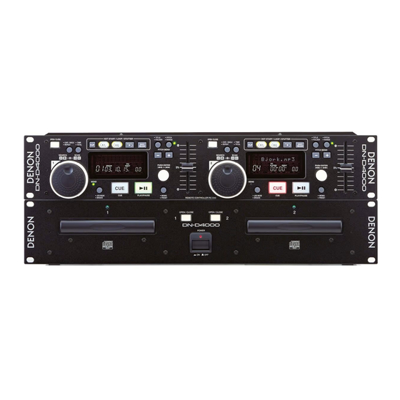
Double cd player
Hide thumbs
Also See for DN-D4000:
- Betriebsanleitung (18 pages) ,
- Operating instructions manual (26 pages) ,
- Operating instructions manual (27 pages)
Advertisement
Quick Links
QQ
3 7 63 1515 0
TE
L 13942296513
Please use this service manual with referring to the
operating instructions without fail.
Some illustrations using in this service manual are
slightly different from the actual set.
www
.
http://www.xiaoyu163.com
SERVICE MANUAL
MODEL
DOUBLE CD PLAYER
x
ao
u163
y
16-11, YUSHIMA 3-CHOME, BUNKYOU-KU, TOKYO 113-0034 JAPAN
Telephone: 03 (3837) 5321
i
http://www.xiaoyu163.com
2 9
8
For U.S.A., Canada, Europe
& Korea model
DN-D4000
Q Q
3
6 7
1 3
1 5
注 意
サービスをおこなう前に、このサービスマニュアルを
必ずお読みください。本機は、火災、感電、けがなど
に対する安全性を確保するために、さまざまな配慮を
おこなっており、また法的には「電気用品安全法」に
もとづき、所定の許可を得て製造されております。
従ってサービスをおこなう際は、これらの安全性が維
持されるよう、このサービスマニュアルに記載されて
いる注意事項を必ずお守りください。
本機の仕様は性能改良のため、予告なく変更する
ことがあります。
補修用性能部品の保有期間は、製造打切後8年です。
修理の際は、必ず取扱説明書を参照の上、作業を
行ってください。
本文中に使用しているイラストは、説明の都合上
現物と多少異なる場合があります。
co
.
9 4
2 8
0 5
8
2 9
9 4
2 8
m
X0171V.02 DE/CDM 0304
9 9
9 9
Advertisement

Related Manuals for Denon DN-D4000


Summary of Contents for Denon DN-D4000
- Page 1 3 7 63 1515 0 For U.S.A., Canada, Europe & Korea model SERVICE MANUAL DN-D4000 MODEL DOUBLE CD PLAYER L 13942296513 注 意 サービスをおこなう前に、このサービスマニュアルを 必ずお読みください。本機は、火災、感電、けがなど に対する安全性を確保するために、さまざまな配慮を おこなっており、また法的には「電気用品安全法」に もとづき、所定の許可を得て製造されております。 従ってサービスをおこなう際は、これらの安全性が維 持されるよう、このサービスマニュアルに記載されて いる注意事項を必ずお守りください。 本機の仕様は性能改良のため、予告なく変更する ことがあります。 補修用性能部品の保有期間は、製造打切後8年です。 Please use this service manual with referring to the 修理の際は、必ず取扱説明書を参照の上、作業を...
-
Page 2: Laser Radiation
DN-D4000 SAFETY PRECAUTIONS 3 7 63 1515 0 The following check should be performed for the continued protection of the customer and service technician. LEAKAGE CURRENT CHECK Before returning the unit to the customer, make sure you make either (1) a leakage current check or (2) a line to chassis resistance check. - Page 3 DN-D4000 DISASSEMBLY 3 7 63 1515 0 (Follow the procedure below in reverse order when reassembling) 1. TOP COVER Remove 4 screws on the both sides, and 1 screw on rear side, then remove 1 upper screw. Pull up Top Cover.
- Page 4 DN-D4000 3. MECHANISM UNIT 3 7 63 1515 0 Disconnect FFC cable. Rrmove 8 lower screws Remove 4 screws on rear side. NOTES: Do notpull out aslant to prevent the FFC cable from damage. Do not fail to pull out AC cord from wall outlet befor disconnecting the FFCcable. If the ACcord is remained plugged into wall outlet, the power is kept supplied in the unit, which may cause danger.
- Page 5 DN-D4000 5. CD MECHA. 3 7 63 1515 0 A gear is turned and a tray is opened. Remove 4 upper screws. Detach CD Mecha. Gear 6. COVER ( REMOTE CONTROL UNIT ) L 13942296513 Remove 5 screws. NOTE:...
- Page 6 DN-D4000 3 7 6 3 1 5 1 5 0 BLOCK DIAGRAM <DN-D4000 DOUBLE CD <DN-D4000 REMOTE PLAYER> CONTROLLER> MAIN UNIT 1 PANEL UNIT 1 LIMIT SW LED BLOCK SLIDE MOTOR 16M DRAM 16M DRAM [14-MT-35GN] JOG SHUTTLE SPINDLE...
- Page 7 DN-D4000 SERVICE PROGRAM 3 7 63 1515 0 Required Measuring Implement 1. Reference disc (TCD784 or CO-74176) 1. What is Service Program Service program is a special program intended for confirming servo functions etc. 2. Contents of Service Program Switch on the power while pushing the CD1’s PITCH BEND + button and CD2’s OPEN/CLOSE button at the same...
-
Page 8: Test Mode
DN-D4000 3 7 63 1515 0 Function Contents (Character-display) Loading a disc by OPEN/CLOSE button. Block Error Rate Check Press the PLAY/PAUSE button. B.E.R. is displayed. “E.Rate_XXX XXX : Block Error Rate You can select the track by the JOG DIAL. - Page 9 DN-D4000 3 7 63 1515 0 4. Error Code Table Error Code CONTENTS E001 Unable to close the loader tray in the regulation time. E002 Unable to open the loader tray in the regulation time. E003 Inner circle switch ON error even if the time is over.
- Page 10 DN-D4000 μCOM VERSION UPGRADE 3 7 63 1515 0 System µcom can be upgraded in the following manner. Version Upgrade Method 1.Record the version upgrade software on a CD-R or CD-RW disc, only as one file with the format ISO9660 Mode-1.
- Page 11 DN-D4000 SEMICONDUCTORS 3 7 63 1515 0 IC’s MN102H60KDA (IC101) MN102H60KDA Terminal Function Pin Name Symbol DET Ext Ini Function P60, WAIT, SBT2 PCDMUTE Mute for analog 'L': Mute ON P61, _RE Read signal L 13942296513 P62, _WEL Write signal...
- Page 12 DN-D4000 3 7 63 1515 0 Pin Name Symbol DET Ext Ini Function P24,A04,TM15IA Unfix Address bus P25,A05 Unfix Address bus P26,A06 Unfix Address bus P27,A07 Unfix Address bus P30,A08,_KI0 Unfix Address bus P31,A09,_KI1 Unfix Address bus P32,A10,_KI2 Unfix...
- Page 13 DN-D4000 3 7 63 1515 0 Pin Name Symbol DET Ext Ini Function P97,AN3 PRCBSYIN Hi-Z Communication Busy signal input between RC and Mecha Power supply(+3.3V) P70,SBT0,_RAS PMCLK Hi-Z H DSP interface Clock (clock synchronous formula) P71,SBI0,_CAS,_LC PSTAT Hi-Z...
- Page 14 DN-D4000 3 7 63 1515 0 MN6627911AC (IC201) MN6627911AC Terminal Function Pin No. Pin Name Function DRVDD Power supply for DRAM interface (Pin No.2 - 18, 80) Data I/O signal 0 for DRAM Data I/O signal 1 for DRAM...
- Page 15 DN-D4000 3 7 63 1515 0 Pin No. Pin Name Function DSLF Loop filter for DSL RFSW Loop filter for DSL PLLF Loop filter for PLL PLLFO Loop filter for PLL AVDD2 Power supply for analog (DSL, PLL, AD)
- Page 16 DN-D4000 3 7 63 1515 0 TMP86CM47U (RC: IC102, 202) TOP VIEW TMP86CM47U Terminal Function Pin Name Symbol DET Ext Ini Function GND (0V) Oscillation input XOUT XOUT Oscillation output TEST TEST Fixed to L Power (+5.0V) LCLK1 CD1:BU2090F-CLK...
- Page 17 DN-D4000 3 7 63 1515 0 Pin Name Symbol DET Ext Ini Function VAREF Power (+5.0V), Analog ref.V for A/D conversion AVDD Power (+5.0V), for A/D conversion circuit only AVSS GND (0V), Analog GND for A/D conversion /KEYIN0 H CD1: Key scan input 0...
- Page 18 DN-D4000 3 7 63 1515 0 AN8785SB (IC202) L: All mute [ Others ] Hiz: ch2,4 ON [ Loading ] [ Traverse ] [ Spindle ] [ Focus ] [ Tracking ] H: Active Standby PVcc2 PVcc3 PVcc1 Protection...
- Page 19 DN-D4000 3 7 63 1515 0 BU2618FV (IC113) L 13942296513 u163 http://www.xiaoyu163.com...
- Page 20 DN-D4000 3 7 63 1515 0 M66005FP (IC601) D I G D I G D I G D I G D I G D I G D i s p l a y C o d e R e g i s t e r...
- Page 21 DN-D4000 3 7 63 1515 0 TC9246F (IC114) Lock Ditection Microcomputer Interface Circuit Programmable Counter Phase Selector Comparator BU2090F (IC602) L 13942296513 Control Circuit DATA 12-bit Shift Register CLOCK Latch Output Buffer (Open Drain) u163 http://www.xiaoyu163.com...
- Page 22 DN-D4000 3 7 63 1515 0 PCM1748 (IC206) DATA LRCK DGND PCM1748 ZEROL/NA ZEROR/ZEROA AGND Serial LRCK Output Amp and Input Low-Pass Filter DATA Enhanced Oversampling Multi-Level Digital Filter Delta-Sigma with L 13942296513 Modulator Function Controller Output Amp and...
- Page 23 DN-D4000 3 7 63 1515 0 FL DISPLAY 14-MT-35GN (FL601) L 13942296513 Pin Connection Pin No. Connection Pin No. 3 4 5 6 7 8 Connection NOTE: 1) F1, F2 Filament 2) NP No Pin 3) DL Datum Line...
- Page 24 DN-D4000 3 7 63 1515 0 Anode Connection L 13942296513 u163 http://www.xiaoyu163.com...
- Page 25 DN-D4000 3 7 6 3 1 5 1 5 0 PRINTED WIRING BOARDS GU-3523 DRIVE P.W.B. UNIT 1 3 9 4 2 2 9 6 5 1 3 w w w u 1 6 3 COMPONENT SIDE http://www.xiaoyu163.com...
- Page 26 DN-D4000 3 7 6 3 1 5 1 5 0 1 3 9 4 2 2 9 6 5 1 3 w w w u 1 6 3 FOIL SIDE http://www.xiaoyu163.com...
- Page 27 DN-D4000 3 7 6 3 1 5 1 5 0 POWER SUPPLY UNIT 1 3 9 4 2 2 9 6 5 1 3 w w w u 1 6 3 COMPONENT SIDE http://www.xiaoyu163.com...
- Page 28 DN-D4000 3 7 6 3 1 5 1 5 0 1 3 9 4 2 2 9 6 5 1 3 w w w u 1 6 3 FOIL SIDE http://www.xiaoyu163.com...
-
Page 29: Note For Parts List
DN-D4000 NOTE FOR PARTS LIST 3 7 63 1515 0 Part indicated with the mark " " are not always in stock and possibly to take a long period of time for supplying, or in some case supplying of part may be refused. - Page 30 DN-D4000 PARTS LIST OF P.W.B. UNIT ASS'Y 3 7 63 1515 0 Note: The symbols in the column "Remarks" indicate the following destinations. E3: U.S.A. model, Csnada model E2K : Koria model E2: Europe model GU-3523 DRIVE P.W.B. UNIT ASS'Y Ref.
- Page 31 DN-D4000 Ref. No. Part No. Part Name Remarks 3 7 63 1515 0 R117 247 2003 989 RM73B--330JT R118 247 2006 960 RM73B--471JT R119 247 2009 983 RM73B--103JT R121 247 2009 912 RM73B--512JT R122 247 2008 968 RM73B--332JT R123...
- Page 32 DN-D4000 Ref. No. Part No. Part Name Remarks 3 7 63 1515 0 R239 247 2011 926 RM73B--393JT R240 247 2008 955 RM73B--302JT R241 247 2007 969 RM73B--122JT R242 247 2006 986 RM73B--561JT R243 247 2018 903 RM73B--0R0KT R244...
- Page 33 DN-D4000 Ref. No. Part No. Part Name Remarks 3 7 63 1515 0 C117 254 4538 955 CE04W1C221MT SMG/RE3 C130 254 4302 958 CE04W1A470MT(SRE) C131 254 4299 964 CE04W1C470MT(SRE) C132 257 0512 903 CK73F1E104ZT C135 257 0512 903 CK73F1E104ZT...
- Page 34 DN-D4000 Ref. No. Part No. Part Name Remarks 3 7 63 1515 0 C253 257 0512 903 CK73F1E104ZT C257 254 4302 916 CE04W1A100MT(SRE) C259 257 0512 903 CK73F1E104ZT C260 257 0509 929 CK73B1H102KT C261 254 4524 956 CE04W1H2R2MT SMG/RE3...
- Page 35 DN-D4000 Ref. No. Part No. Part Name Remarks 3 7 63 1515 0 S601 212 0352 018 JOG-SHUTTLE S604 212 5604 907 TACT SWITCH-TA(ALPS) S608 212 5604 907 TACT SWITCH-TA(ALPS) S612 212 5604 907 TACT SWITCH-TA(ALPS) S616 212 5604 907...
- Page 36 DN-D4000 POWER SUPPLY UNIT ASS’Y 3 7 63 1515 0 Ref. No. Part No. Part Name Remarks SEMICONDUCTORS GROUP IC301 263 0913 905 PST600C TP IC302 262 2813 903 SN74AHCT08PW-EL2 IC303 263 1178 901 AN80L18RMS IC308 263 1048 002...
- Page 37 DN-D4000 Ref. No. Part No. Part Name Remarks 3 7 63 1515 0 R429 247 2006 915 RM73B--271JT R430-439 247 2009 983 RM73B--103JT R441-449 247 2009 983 RM73B--103JT R458 247 2009 983 RM73B--103JT CAPACITORS GROUP C301-310 257 0512 903...
- Page 38 DN-D4000 Ref. No. Part No. Part Name Remarks 3 7 63 1515 0 FH305,306 202 0040 909 FUSE CLIP (TAPE) L301 235 0159 007 PLH10AN3711ROP2B S301 212 1176 015 POWER SWITCH(TV-5) S302,303 212 5604 907 TACT SWITCH-TA(ALPS) X401 399 0805 901...
- Page 39 DN-D4000 3 7 6 3 1 5 1 5 0 EXPLODED VIEW OF REMOTE CONTROL UNIT 1 3 9 4 2 2 9 6 5 1 3 w w w u 1 6 3 http://www.xiaoyu163.com...
- Page 40 DN-D4000 PARTS LIST OF EXPLODED VIEW (REMOTE CONTROL UNIT) 3 7 63 1515 0 Ref. No. Part No. Part Name Remarks Q'ty 441 1984 009 RC FRONT SUB PANEL 144 2832 107 RC FRONT PANEL 143 1072 004 LENS...
- Page 41 DN-D4000 3 7 6 3 1 5 1 5 0 EXPLODED VIEW OF CHASSIS AND CABINET WARNING: Parts marked with this symbol have critical characteristics. Use ONLY replacement parts recommended by the manufacturer. 1 3 9 4 2 2 9 6 5 1 3...
-
Page 42: Panel Unit
DN-D4000 PARTS LIST OF EXPLODED VIEW (CHASSIS AND CABINET) 3 7 63 1515 0 Note: The symbols in the column "Remarks" indicate the following destinations. E3: U.S.A. model, Csnada model E2K : Koria model E2: Europe model Ref. No. -
Page 43: Dn-D4000
DN-D4000 Ref. No. Part No. Part Name Remarks Q'ty 3 7 63 1515 0 513 3326 009 BAR CODE LABEL FILM ★ GEN6154 MANUFAC.DATE SUB ASS ★ SCREWS 473 7015 018 3X8 CBTS (S)-B 473 7002 005 3X6 CBTS(S)-Z... -
Page 44: Http://Www.xiaoyu163.Com
DN-D4000 EXPLODED VIEW OF CD MECHANISM UNIT (CD11FTA3N) 3 7 63 1515 0 L 13942296513 PARTS LIST OF CD MECHANISM UNIT Ref. No. Part No. Part Name Remarks Q'ty Ref. No. Part No. Part Name Remarks Q'ty 1 964 0009 006 Frame chassis... -
Page 45: Dn-D4000
DN-D4000 PACKING VIEW 3 7 63 1515 0 L 13942296513 PARTS LIST OF PACKING & ACCESSORIES Note: The symbols in the column "Remarks" indicate the following destinations. E3: U.S.A. model, Csnada model E2K : Koria model E2: Europe model Ref. -
Page 46: Dn-D4000
DN-D4000 3 7 6 3 1 5 1 5 0 WIRING DIAGRAM DN-D4000 DOUBLE CD PLAYER REMOTE CONTROLLER CX041 CW041 CX051 +3.3V 1 1 +3.3V LOAD- 1 1 LOAD- /EJECT 2 2 /EJECT GU−3524−3 LED1 UNIT LOAD+ 2 2 LOAD+... - Page 47 DN-D4000 NOTE FOR SCHEMATIC DIAGRAM 3 7 63 1515 0 WARNING: Parts marked with this symbol have critical characteristics. Use ONLY replacement parts recommended by the manufacturer. CAUTION: Before returning the unit to the customer, make sure you make either (1) a leakage current check or (2) a line to chassis resistance check.
- Page 48 DN-D4000 3 7 6 3 1 5 1 5 0 SCHEMATIC DIAGRAMS (1/3) 1 3 9 4 2 2 9 6 5 1 3 w w w REC SIGNAL LINE u 1 6 3 SCHEMATIC DIAGRAMS (1/3) GU-3523-1 http://www.xiaoyu163.com...
- Page 49 DN-D4000 3 7 6 3 1 5 1 5 0 SCHEMATIC DIAGRAMS (2/3) 1 3 9 4 2 2 9 6 5 1 3 D614 1SS355 w w w u 1 6 3 SCHEMATIC DIAGRAMS (2/3) GU-3523-2 http://www.xiaoyu163.com...
- Page 50 DN-D4000 3 7 6 3 1 5 1 5 0 SCHEMATIC DIAGRAMS (3/3) 1 3 9 4 2 2 9 6 5 1 3 w w w u 1 6 3 SCHEMATIC DIAGRAMS (3/3) GU-3524-1 GU-3524-2 GU-3524-3 GU-3524-4 http://www.xiaoyu163.com...