Table of Contents
Advertisement
Quick Links
Advertisement
Table of Contents

Related Manuals for Acer TRAVELMATE 7730


Summary of Contents for Acer TRAVELMATE 7730
- Page 1 TravelMate 7730/7730A Service Guide...
-
Page 2: Revision History
Revision History Please refer to the table below for the updates made on Travelmate 7730/7730G Series service guide. Date Service guide files and updates are available on the ACER/CSD web. For more information, refer Copyright Copyright © 2008 by Acer Incorporated. All rights reserved. No part of this publication may be... - Page 3 Guide. For ACER-AUTHORIZED SERVICE PROVIDERS, your Acer office may have a DIFFERENT part number code to those given in the FRU list of this printed Service Guide. You MUST use the list provided by your regional Acer office to order FRU parts for repair and service of customer machines.
-
Page 5: Table Of Contents
The Acer notebook tour ........6... - Page 6 Security screen ........41 Boot .
- Page 7 Notebook LCD panel ....... . .164 Travelmate 7730/7730G FRU list ......165...
- Page 8 VIII Contents...
-
Page 9: Chapter 1: System Specifications
TravelMate 7730/7730G Chapter 1 System specifications Features ❑ System block diagram ❑ The Acer notebook tour ❑ Using the keyboard ❑ Hardware specifications and configurations ❑... -
Page 10: Features
17" WXGA+ high-brightness (220 nit), 1440 × 900 pixel resolution, supporting ❑ simultaneous multi-window viewing via Acer GridVista™ 17" WXGA+ high-brightness (220 nit) Acer CrystalBrite™ TFT LCD, 1440 × 900 pixel ❑ resolution, supporting simultaneous multi-window viewing via Acer GridVista™... - Page 11 ❑ Empowering Key ❑ Easy-launch buttons: WLAN, Internet, Bluetooth, email, programmable ❑ Productivity keys: Lock, Presentation, Sync ❑ Audio Two built-in Acer 3DSonic stereo speakers ❑ High-definition audio support ❑ MS-Sound compatible ❑ Built-in microphone ❑ Chapter 1: System specifications ®...
- Page 12 Communication Acer Video Conference, featuring: ❑ Integrated Acer Crystal Eye webcam, supporting enhanced Acer PrimaLite™ ❑ technology Optional Acer Xpress VoIP phone ❑ ® WLAN: Intel ❑ Draft-N) Wi-Fi CERTIFIED supporting Acer SignalUp™ with Nplify™2 wireless technology WPAN: Bluetooth ❑...
-
Page 13: System Block Diagram
System block diagram Chapter 1: System specifications... -
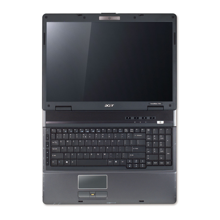
Page 14: The Acer Notebook Tour
The Acer notebook tour LCD panel Display screen Item Display screen Also called Liquid-Crystal Display (LCD), displays video output. Acer Crystal Eye Web camera for video communication. (Available on select models only.) Acer Crystal Eye Description Chapter 1: System specifications... -
Page 15: Palm Rest
Click buttons (left, The left and right buttons function like the left and right mouse buttons. center, and right) Note: The center button serves as Acer BioProtect fingerprint reader supporting Acer FingerNav 4-way control function. (Available on select models only.) Keyboard For entering data into your notebook. -
Page 16: Front
Front Item Icon Latch 5-in-1 card reader Latch 5-in-1 card reader Description Locks and releases the lid. Accepts Secure Digital (SD), MultiMediaCard (MMC), Memory Stick (MS), Memory Stick Pro (MS PRO), and xD-Picture Card. Note: Push to remove or install a card. Only one card can operate at any given time. -
Page 17: Left
USB ports Icon Connects to an AC adapter. Connects to an Ethernet 10/100/1000-based network. Connects to an Acer EasyPort IV. (Available on select models only.) Connects to a display device (such as an external monitor or LCD projector). HDMI Connects to a high definition digital video device. -
Page 18: Right
Right USB ports ExpressCard slot Item Type 54 ExpressCard slot USB 2.0 ports Optical drive Optical disc access indicator Optical drive eject button Emergency eject hole Modem (RJ-11) port Kensington lock slot Rear Item Ventilation slots Helps cool internal components. Warning: Do not work with the notebook resting on your lap. -
Page 19: Bottom View
Bottom view Battery release latch Item Battery bay Battery release latch Hard disk bay-Main Acer DASP (Disk Anti-Shock Protection) Hard disk bay-Secondary Memory bay Battery lock Chapter 1: System specifications Battery lock Battery Acer DASP Main hard disk bay Icon Houses the notebook's battery pack. -
Page 20: Indicators
Indicators The notebook has several easy-to-read status indicators: Front panel indicators The front panel indicators are visible even when the notebook cover is closed. Icon Function Power Battery Hard Disk Drive (HDD) Num Lock Caps Lock Palm rest indicators Indicates the notebook's power status. Indicates the notebook's battery status. -
Page 21: Easy-Launch Buttons
They are: WLAN, Internet, email, Bluetooth, Arcade and Acer Empowering Technology. The mail and Web browser buttons are pre-set to email and Internet programs, but can be reset by the user. To set the Web browser, mail, and programmable buttons, run the Acer Launch Manager. -
Page 22: Touchpad Basics
Touchpad basics The following teaches you how to use the touchpad: Left button Move your finger across the touchpad to move the cursor. ❑ Press the left and right buttons located beneath the touchpad to perform selection ❑ and execution functions. These two buttons are similar to the left and right buttons on a mouse. - Page 23 Lock keys The keyboard has three lock keys which you can toggle on and off. Caps lock Lock key Caps Lock When Caps Lock is on, all alphabetic characters typed are in uppercase. Scroll Lock <Fn> + <F12> When Scroll Lock is on, the screen moves one line up or down when you press the up or down arrow keys respectively.
- Page 24 Windows keys The keyboard has two keys that perform Windows-specific functions. Windows key Windows Pressed alone, this key has the same effect as clicking on the Windows Start button. It launches the Start menu. It can also be used with other keys to provide a variety of functions: <...
- Page 25 <Fn> + < > Chapter 1: System specifications Hotkeys Hotkeys Function Hotkey help Displays help on hotkeys. Acer eSettings Launches Acer eSettings Management in Acer Management Empowering Technology. Acer ePower Launches Acer ePower Management in Acer Management Empowering Technology. Sleep Puts the notebook in Sleep mode.
-
Page 26: Hardware Specifications And Configurations
Hardware specifications and configurations Item CPU type Core logic CPU package CPU core voltage Controllers Item Core logic USB 2.0 Super I/O controller MODEM Bluetooth Wireless 802.11 b+g PCMCIA 5 in 1 Card Reader Audio Codec BIOS Item BIOS vendor BIOS Version BIOS ROM type BIOS ROM size... -
Page 27: Memory
Item Supported protocols BIOS password control Memory Item Memory controller Memory size SO-DIMM socket number Supports memory size per socket Supports maximum memory size Supports SO-DIMM type Supports SO-DIMM Speed Supports SO-DIMM voltage • 1.8 V for DDR 2 Supports SO-DIMM package Memory module combinations... -
Page 28: Hard Disk Drive
Slot 1 256MB 256MB 256MB 256MB 512MB 512MB 512MB 512MB 1024MB 1024MB 1024MB 1024MB 1024MB 2048MB 2048MB 2048MB 2048MB 2048MB Note: Above table lists some system memory configurations. You may combine SO-DIMMs with various capacities to form other combinations. On above table, the configuration of slot 1 and slot 2 can be reversed. - Page 29 Item Data transfer rate 300 Mbit/sec (host~buffer) Ultra DMA mode 6 Input Voltage Item Vendor & Model Name Toshiba MK2546GSX Capacity 250 GB Bytes per sector Data heads Disks Spindle speed 5400 RPM Buffer size 8 MB Interface SATA Max. media transfer 730 Mbits/sec rate (disk-buffer) Data transfer rate...
-
Page 30: Dvd-Cdrw Drive
DVD-CDRW drive Item Vendor & model name Sony CRX890S Performance Specification Transfer rate Buffer Memory 2 MB Interface SATA Applicable disc format Applicable CD Formats: Read: • CD-Audio • CD-DA • CD-Extra/CD-Plus • CD-I • CD-ROM • CD-ROM XA • CD-TEXT •... -
Page 31: Dvd Burner
Item Loading mechanism Tray Input Voltage DVD burner Item Vendor & model name HLDS GSA-T50N Performance Specification Transfer rate 3600 KB/s Buffer Memory 2 MB Interface SATA Applicable disc format Applicable CD Formats: Read: • CD-Audio • CD-DA • CD-Extra/CD-Plus •... - Page 32 Item Applicable disc format Applicable CD Formats: Read: • CD-Audio • CD-DA • CD-Extra/CD-Plus • CD-ROM • CD-ROM XA • CD-TEXT • Photo CD • Video CD Write: • CD-R • CD-RW Loading mechanism Tray Input Voltage Item Vendor & model name Toshiba TS-L633A Performance Specification...
-
Page 33: Blu-Ray Drive
Blu-ray drive Item Vendor & model name Sony NEC Optiarc BC-5500S-AR Performance Specification Transfer rate 600–3600 KB/sec Buffer Memory 4.5 MB Interface SATA Applicable disc format Applicable CD Formats: Read: • CD-Audio • CD Extra • CD-I (FMV) • CD-ROM •... - Page 34 Item Nominal Input Voltage Typical Power Consumption Weight (without inverter) Physical Size Electrical Interface Surface Support Color Viewing Angle Temperature Range Item Vendor & model name Screen Diagonal Active Area (horizontal × vertical) Display resolution (pixels) Pixel Pitch Pixel Arrangement Display Mode Typical White Luminance (also called Brightness)
- Page 35 Item Vendor & model name Screen Diagonal (mm) Active Area (horizontal × vertical) Display resolution (pixels) Pixel Pitch Pixel Arrangement Display Mode Typical White Luminance (also called Brightness) Luminance Uniformity Contrast Ratio Response Time (Optical Rise Time/Fall Time) Nominal Input Voltage Typical Power Consumption Weight (without inverter)
-
Page 36: Inverter
Item Physical Size Electrical Interface Surface Support Color Viewing Angle Temperature Range Inverter Item Vendor & model name Brightness conditions Input voltage (V) Input current (mA) Output voltage (V, rms) Output current (mA, rms) Output voltage frequency (k Hz) Video subsystem Item Chipset Memory size... -
Page 37: Keyboard
Keyboard Item Keyboard controller Total number of keypads Windows logo key Internal & external keyboard work simultaneously Pointing device Item Type Buttons Scrolling Memory card reader Item Controller Cards supported Compliancy PCMCIA Item PCMCIA controller Supports card type Number of slots Access location Supports ZV (Zoomed Video) port... -
Page 38: Audio
Item Access location Audio Item Audio Controller Audio onboard or optional Built-in Mono or Stereo Resolution Compatibility Sampling rate Internal microphone Internal speaker / Quantity Features Wired LAN Item LAN Chipset Supports LAN protocol LAN connector type LAN connector location Features Bluetooth Item... -
Page 39: Wireless Lan
Wireless LAN Item Chipset Data throughput Protocol Interface Modem Item Chipset Protocol Interface Item Chipset USB Compliancy Level OHCI Number of USB port Location Serial port function control Enable/Disable by BIOS Setup Buttons/Indicators/Ports Item Buttons Chapter 1: System specifications Specification Intel 11~54 Mbps, up to 270 Mbps for Draft-N •... -
Page 40: Fingerprint Reader
Item Indicators Ports & Slots Fingerprint reader Item Interface Resolution Technology Power Camera Item Interface Resolution CPU Temperature Fan Speed (rpm) 113°F (45°C) 122°F (50°C) 149°F (65°C) • 2 keyboard indicators (CAPS Lock and NUM Lock) • HDD/CD-ROM active LED •... -
Page 41: Battery
CPU Temperature Fan Speed (rpm) 172°F (78°C) 194°F (90°C) Throttling 50%: On= 105° C; OFF=95° C OS shut down at 110° C; H/W shut down at 110°C Battery Item Vendor Battery Type Pack capacity Number of battery cell Package configuration Normal voltage Charge voltage Power supply... - Page 42 Chapter 1: System specifications...
-
Page 43: Chapter 2: System Utilities
TravelMate 7730/7730G Chapter 2 System utilities BIOS Setup Utility ❑ BIOS Flash utility ❑ Removing a password lock ❑... -
Page 44: Bios Setup Utility
BIOS Setup Utility The BIOS Setup Utility is a hardware configuration program built into the notebook’s BIOS (Basic Input/Output System). The notebook was shipped already properly configured and optimized. However, if the user encounters configuration problems, you may need to run Setup. Note: Also see Chapter 4 “Clearing password check and BIOS recovery”... -
Page 45: Bios Setup Utility Screens
In any menu, you can load default settings by pressing F9. You can also press F10 to ❑ save any changes made and exit the BIOS Setup Utility. Note: You can change the value of a parameter if it is enclosed in square brackets. -
Page 46: Main Screen
Parameter Serial Number Shows the notebook’s serial number. Asset Tag Number Shows the notebook’s asset tag number. Product Name Shows the notebook’s product name. Manufacturer Name Shows the notebook’s manufacturer. UUID Number Shows the notebook’s Universally Unique Identifier number. The UUID is an identifier standard used in software construction. - Page 47 Shows the VGA memory size. VGA Memory size= 256 or 512 MB Quiet Boot Determines if the Acer logo will be displayed or not. Also determines if the Summary Screen is disabled or enabled. Enabled: The Acer logo is displayed and the Summary Screen is not displayed.
-
Page 48: Advanced Screen
Advanced screen The Advanced screen allows the user to configure the Alert Standard Format parameters. The table below describes the parameters found on the ASF Configuration sub menu screen. Parameter Minimum WatchDog Timeout Time for BIOS to stop the WatchDog timer after a reset has occurred. BIOS Boot Timeout SO Boot Timeout Power-on wait time... -
Page 49: Security Screen
Security screen The Security screen contains parameters that help safeguard and protect your notebook from unauthorized use. Note: Refer to “Removing a password lock” on page 48 if you need to know how to remove a Hard Drive or BIOS Password. The table below describes the parameters in this screen. - Page 50 Parameter Supervisor Password Is User Password Is HDD Password Is Set Supervisor Password Set User Password Set HDD Password Password on Boot Caution: When you are prompted to enter a password, you have three tries before the system halts. Don’t forget your password. If you forget your password, you may have to return your notebook to your dealer to reset it.
- Page 51 Optional: you can enable the Password on Boot parameter. When you are done, press F10 to save your password and exit the BIOS Setup Utility or you can proceed to setting the User password. To set the User password: ↑ ↓...
- Page 52 Type the current password in the Enter Current Password field, then press E Note: If you enter an incorrect current password, the screen displays the following. Press E , then re-enter the current password. NTER Type a password in the Enter New Password field. Retype the password in the Confirm New Password field.
-
Page 53: Boot
Boot This menu allows the user to decide the order of boot devices to load the operating system. Bootable devices include the onboard hard disk drive and the optical drive. Follow the instructions in Item Specific Help to change to boot order of the notebook devices. Chapter 2: System utilities... -
Page 54: Exit
Exit The Exit screen contains options for leaving the BIOS Setup Utility and starting Windows. The table below describes the options on this screen. Option Exit Saving Changes Exit the BIOS Setup Utility and save your changes to CMOS. Exit Discarding Changes Exit the BIOS Setup Utility without saving your changes to CMOS. -
Page 55: Bios Flash Utility
BIOS Flash utility Use the BIOS flash memory update for the following conditions: New versions of system programs (such as HDD_PW or bios_pw). ❑ New BIOS features or options. ❑ Restore a BIOS when it becomes corrupted. ❑ Use the Phlash utility to update the system BIOS flash ROM. Note: If you do not have a crisis recovery diskette at hand, then you should create a Crisis Recovery Diskette before you use the Phlash utility. -
Page 56: Removing A Password Lock
HDD_PW.EXE. To remove the HDD password: On a working Acer notebook, click Start, then Run. The Type cmd in the Open field, then click OK. Type hdd_pw 15494 0. Select 2 Upper case ASCII Code. - Page 57 Type bios_pw 14452 0. Choose one of the strings. In this example you can choose either Reboot the notebook that is locked, then enter either Supervisor password. Chapter 2: System utilities qjjg9vy or 07yqmjd. for the qjjg9vy or 07yqmjd...
- Page 58 Chapter 2: System utilities...
-
Page 59: Chapter 3: Replacing Notebook Components
TravelMate 7730/7730G Chapter 3 Replacing notebook components Preventing static electricity discharge ❑ Preparing your work space ❑ Tools required ❑ Preparing the notebook ❑ Adding or replacing memory modules ❑ Replacing the graphics card ❑ Replacing the primary hard drive ❑... -
Page 60: Preventing Static Electricity Discharge
Preventing static electricity discharge Warning: To avoid exposure to dangerous electrical voltages and moving parts, turn off your notebook, remove the battery, and unplug the power cord, modem cable, and network cable before opening the case. Warning: To prevent risk of electric shock, do not insert any object into the vent holes of the notebook. -
Page 61: Preparing Your Work Space
Preparing your work space Before performing maintenance on the notebook, make sure that your work space and the notebook are correctly prepared. Wear a grounding (ESD) wrist strap, and use a grounded or dissipative work mat. ❑ Use a stable and strong table, and make sure that the table top is large enough to ❑... -
Page 62: Tools Required
Tools required To disassemble the notebook, you need the following tools: Wrist grounding strap and conductive mat for preventing electrostatic discharge ❑ Flat screwdriver ❑ Philips screwdriver ❑ Scribe or non-marring tool ❑ Tweezers ❑ Chapter 3: Replacing notebook components... -
Page 63: Preparing The Notebook
Preparing the notebook To prepare the notebook for maintenance: Make sure that the disc drive is empty. Turn off the notebook. Close the LCD panel Disconnect the AC adapter, modem cable, and network cable. Disconnect all peripheral devices connected to the notebook and remove any PC Cards, Express Cards, and memory cards. -
Page 64: Removing A Memory Card
Pull the ExpressCard all the way out of the notebook. Removing a memory card To remove a memory card: Push the memory card all the way into the notebook. Pull the memory card all the way out of the notebook. Removing the battery To remove the battery: Turn the notebook over so the bottom is facing up. -
Page 65: Adding Or Replacing Memory Modules
Adding or replacing memory modules Important: Tools you need to complete this task: Locating components: To add or replace memory modules: Complete the steps in Loosen the memory bay cover screws (these screws cannot be removed). Screw Chapter 3: Replacing notebook components Use only memory modules designed for this notebook. - Page 66 Use the thumb notch to lift the memory bay cover, then remove it. Be careful not to break off the tabs located on the end of the cover opposite the thumb notch. Thumb notch If you are removing a module, gently press outward on the clip at each end of the memory module until the module tilts upward.
- Page 67 Pull the memory module out of the slot. Chapter 3: Replacing notebook components...
- Page 68 Hold the new or replacement module at a 30-degree angle and press it into the empty memory slot. This module is keyed so it can only be inserted in one direction. If the module does not fit, make sure that the notch in the module lines up with the tab in the memory slot.
-
Page 69: Replacing The Graphics Card
Replacing the graphics card Important: Tools you need to complete this task: Additional materials you need to complete this task: X-23-7762 thermal grease ❑ Screws removed during this task: 4 black M2.5×8 (graphics card) Locating components: To replace the graphics card: Complete the steps in Chapter 3: Replacing notebook components Use only graphics cards designed for this notebook. - Page 70 Loosen the graphics card bay cover screws (these screws cannot be removed). Screw Use the thumb notch to lift the graphics card bay cover, then remove it. Be careful not to break off the tabs located on the end of the cover opposite the thumb notch.
- Page 71 Pull the card out of the slot. Remove any thermal grease residue from the cooling assembly using a soft cloth and isopropyl alcohol. Thermal grease Place new thermal grease on the graphics card. Use only enough to cover the graphics processor die. Hold the new card at a 30-degree angle and slide it into the empty slot.
-
Page 72: Replacing The Primary Hard Drive
Replacing the primary hard drive Tools you need to complete this task: Screws removed during this task: 4 chrome M3×3.5 (Hard drive bracket) Locating components: Primary hard drive bay To replace the primary hard drive: Complete the steps in Loosen the hard drive bay cover screws (these screws cannot be removed). Phillips #0 screwdriver “Preparing the notebook”... - Page 73 Use the thumb notch to lift the hard drive bay cover, then remove it. Be careful not to break off the tabs located on the end of the cover opposite the thumb notch. Using the plastic tab, lift straight up on the hard drive, then remove it. If your new hard drive already includes the hard drive bracket, go to step -OR- If you need to move the hard drive bracket from your old hard drive to your new...
- Page 74 Remove the bracket from the old drive. Insert the new drive label side up onto the bracket so the screw holes line up. Replace the screws that secure the bracket to the drive. Slide the new hard drive kit into your notebook. Replace the cover, then tighten the screws.
-
Page 75: Replacing The Ieee 802.11 Wireless Card
Replacing the IEEE 802.11 wireless card Important: Tools you need to complete this task: Screws removed during this task: 2 chrome M2×3 (IEEE 802.11 wireless card) Locating components: To replace the IEEE 802.11 wireless card: Complete the steps in Loosen the wireless bay cover screws (these screws cannot be removed). Screw Chapter 3: Replacing notebook components Use only wireless cards designed for this notebook. - Page 76 Use the thumb notch to lift the wireless bay cover, then remove it. Be careful not to break off the tabs located on the end of the cover opposite the thumb notch. Thumb notch Unplug the antenna cables. Note which color cable is connected to each of the connectors.
- Page 77 Remove the wireless card screws. Pull the card out of the slot. Move the antenna cables out of the way. Hold the new card at a 30-degree angle and slide it into the empty slot. This card is keyed so it can only be inserted in one direction. If the card does not fit, make sure that the notch in the card lines up with the tab in the card slot.
- Page 78 Replace the screws removed in Reattach the antenna cables to the connectors. Replace the wireless bay cover, then tighten the cover screws. Step Chapter 3: Replacing notebook components...
-
Page 79: Replacing The Cmos Battery
Replacing the CMOS battery Important: Tools you need to complete this task: Screws removed during this task: 2 chrome M2×3 (IEEE 802.11 wireless card) Locating components: To replace the CMOS battery: Complete the steps in Remove the optional IEEE 802.11 wireless card by following the instructions in “Replacing the IEEE 802.11 wireless card”... - Page 80 Insert the small flat-blade screwdriver or non-marring tool under the old battery and gently pry it up until it pops out of the socket. Make sure that the positive (+) side of the new battery is facing up, then press the battery into the socket until it snaps into place.
-
Page 81: Replacing The Secondary Hard Drive
Replacing the secondary hard drive Tools you need to complete this task: Screws removed during this task: 4 chrome M3×3.5 (Hard drive bracket) Locating components: To replace the secondary hard drive: Complete the steps in Loosen the hard drive bay cover screws (these screws cannot be removed). Screw Chapter 3: Replacing notebook components Phillips #0 screwdriver... - Page 82 Use the thumb notch to lift the hard drive bay cover, then remove it. Be careful not to break off the tabs located on the end of the cover opposite the thumb notch. Thumb notch Using the plastic tab, lift straight up on the hard drive, then remove it. If your new hard drive already includes the hard drive bracket, go to step -OR- If you need to move the hard drive bracket from your old hard drive to your new...
- Page 83 Remove the bracket from the old drive. Insert the new drive label side up onto the bracket so the screw holes line up. Replace the screws that secure the bracket to the drive. Slide the new hard drive kit into your notebook. Replace the cover, then tighten the screws.
-
Page 84: Replacing The Optical Drive
Replacing the optical drive Tools you need to complete this task: Locating components: Optical drive To replace the optical drive: Complete the steps in Remove the screw and cover that secures the DVD drive to your notebook. Flat-blade driver - OR - Phillips #0 screwdriver “Preparing the notebook”... - Page 85 Carefully slide the drive out of the drive bay. Important: DVD bracket and slide the drive out of the bay. Slide the new DVD drive into the drive bay. Make sure that the drive fits securely in the bay. Replace the screw and cover removed in Chapter 3: Replacing notebook components Use a small screwdriver or other pointed tool to push on the DVD bracket...
-
Page 86: Replacing The Keyboard Cover
Replacing the keyboard cover Tools you need to complete this task Screws removed during this task: 2 black M2.5×5 (Keyboard cover) To replace the keyboard cover: Complete the steps in Remove the two keyboard cover screws from the inside of the battery compartment. - Page 87 Insert the small flat-blade screwdriver under each end of the keyboard cover and gently pry it up. Pull the cover off the notebook by lifting the back corners of the cover. Be careful to not damage the LCD panel. Replace the keyboard cover by first inserting the tabs located on the front of the cover into the slots provided, then pressing down on the back.
-
Page 88: Replacing The Keyboard
Replacing the keyboard Tools you need to complete this task: Screws removed during this task: 2 black M2.5×5 (Keyboard cover) To replace the keyboard: Complete the steps in Remove the keyboard cover by following the steps in cover” on page Lift the center of the back edge of the keyboard slightly and, at the same time, press inward on the left side and then the right side. - Page 89 Swing the keyboard connector clip upward, then slide the cable out of the clip. Be careful not to touch or damage any other components. Place the new keyboard keys-down on your notebook with the space bar away from you. Make sure the keyboard connector clip is fully lifted up, insert the cable into the connector, then swing the clip downward to lock the connector in place.
-
Page 90: Replacing The Power Button Board
Replacing the power button board Tools you need to complete this task: Screws removed during this task: 2 black M2.5×5 (Keyboard cover) To replace the status indicator board: Complete the steps in Remove the keyboard cover by following the steps in cover”... - Page 91 Remove the screws connecting the power button board to the notebook. Screw Replace the power button board, then replace the screws removed in Make sure the black connector clip on the new power button board is swung upward, insert the cable into the connector, then swing the clip down to lock the connector in place.
-
Page 92: Replacing The Lcd Assembly
If the notebook has wireless networking built in, unplug the wireless antennas by following the steps in Taking care to note the cables’ routing and positions as they are installed from Acer, slide the antenna cables out of the wireless bay. Flat-blade driver - OR - Phillips #0 screwdriver 2 black M2.5×6.5... - Page 93 Remove the screws on the bottom that secure the LCD panel hinges to the chassis. Screw Remove the keyboard cover by following the steps in cover” on page Remove the keyboard by following the steps in Detach the LCD cable from the system board. Use a scribe or other non-marring tool to gently push the plug out of the connector.
-
Page 94: Card" On Page
Taking care to note the cables’ routing and positions as they are installed from Acer, pull the antenna cables out from under the system board, then slide the antenna cables and LCD cables out from under the retaining clips. Remove the screws on the top that secure the LCD panel hinge to the chassis. -
Page 95: Replacing The Inverter
Replacing the inverter Tools you need to complete this task: Screws removed during this task: 2 black M2.5×5 (Keyboard cover) 6 black M2.5×5 (LCD front panel) To replace the inverter: Complete the steps in Remove the LCD panel by following the steps in page Remove the rubber inserts from the front of the LCD panel assembly. - Page 96 Remove the screws from the front of the LCD panel assembly. Screw Screw Carefully separate the front and back of the LCD panel assembly. Lift the inverter from the LCD panel assembly. Disconnect the connectors from the old inverter and connect them to the new inverter.
-
Page 97: Replacing The Lcd Panel
Replacing the LCD panel Tools you need to complete this task: Screws removed during this task: 2 black M2.5×5 (Keyboard cover) 6 black M2.5×5 (LCD front panel) 4 chrome M2×3 (Hinge bracket) To replace the LCD panel: Complete the steps in Remove the LCD panel by following the steps in page Chapter 3: Replacing notebook components... - Page 98 Remove the rubber inserts from the front of the LCD panel assembly. Insert Insert Remove the screws from the front of the LCD panel assembly. Screw Screw Carefully separate the front and back of the LCD panel assembly. Insert Insert Screw Screw Chapter 3: Replacing notebook components...
- Page 99 Remove the grounding screw from the LCD panel lid. Remove the screws that secure the LCD panel to the LCD panel lid. Screw Screw Screw Screw Remove the inverter by following the steps in Remove the old LCD panel from the LCD panel lid. Remove the hinges from the old LCD panel and install them on the new panel by following the steps in Remove the web cam from the old LCD panel and install it on the new panel by...
-
Page 100: Replacing The Lcd Panel Hinges
Replacing the LCD panel hinges Tools you need to complete this task: Screws removed during this task: 2 black M2.5×5 (Keyboard cover) 6 black M2.5×5 (LCD front panel) 4 chrome M2×3 (Hinge bracket) To replace the LCD panel hinges: Complete the steps in Remove the LCD panel assembly by following the steps in assembly”... - Page 101 Replace the screws that were removed in Replace the LCD panel by following the steps in Replace the LCD assembly by following the steps in on page Chapter 3: Replacing notebook components Step “Replacing the LCD panel” on page “Replacing the LCD assembly”...
-
Page 102: Replacing The Web Cam
Replacing the web cam Tools you need to complete this task: Screws removed during this task: 2 black M2.5×5 (Keyboard cover) 6 black M2.5×5 (LCD front panel) 2 chrome M2×3 (Web cam) To replace the web cam: Complete the steps in Remove the LCD panel by following the steps in page Remove the LCD panel by following the steps in... - Page 103 Remove the screws that secure the LCD panel to the LCD panel lid. Screw Replace the screws that were removed in Reconnect the connector from the web cam. Replace the LCD panel by following the steps in Replace the LCD assembly by following the steps in on page Chapter 3: Replacing notebook components Screw...
-
Page 106: Replacing The Palm Rest
Replacing the palm rest Tools you need to complete this task: Screws removed during this task: 2 black M2.5×5 (Keyboard cover) 1 black M2.5×8 (Keyboard plate) 3 black M2.5×5 (Palm rest-bottom) 2 black M2.5×8 (Speaker-Left) 3 black M2.5×4 (Button board) Flat-blade driver - OR - Phillips #0 screwdriver... - Page 107 To replace the palm rest: Complete the steps in Remove the memory bay cover by following the steps in memory modules” on page If the notebook has wireless networking built in, unplug the wireless antennas by following the steps in Remove the hard drive(s) by following the steps in drive”...
- Page 108 Swing the black touchpad connector clip upward, then lift the touchpad cable out of the connector. Be careful not to touch or damage any other components. Touchpad connector Disconnect the finger print reader cable from the system board. Use a scribe or other non-marring tool to gently push the plug out of the connector.
- Page 109 Swing the black button board connector clip upward, then lift the button board cable out of the connector. Be careful not to touch or damage any other components. Remove the screws from the top of the palm rest. Screw Screw Turn the notebook over so the bottom is facing up.
- Page 110 Disconnect the microphone and speaker cables from the system board. Use a scribe or other non-marring tool to gently lift the plugs out of the connectors. Chapter 3: Replacing notebook components...
- Page 111 Turn the notebook over so the top is facing up. Taking care to note the cables’ routing and positions as they are installed from Acer, pull the microphone and speaker cables out from under the system board. Chapter 3: Replacing notebook components...
- Page 112 Lift the palm rest assembly up from the notebook. Remove the speakers and microphone from the old palm rest and install them on the new palm rest by following the instructions in speakers” on page Remove the touchpad button board/fingerprint assembly from the old palm rest and install it on the new palm rest by following the instructions in touchpad button board/fingerprint assembly”...
-
Page 113: Replacing The Microphone And Speakers
Replacing the microphone and speakers <Athena, do speakers and microphone get replaced? The screws are not in the Screw BOM. The microphone and speakers are listed in the Replacement Parts List.> Tools you need to complete this task: Screws removed during this task: 2 black M2.5×5 (Keyboard cover) 1 black... -
Page 114: If The Notebook Has Wireless Networking Built In, Unplug The Wireless Antennas By Following The Steps In
If the notebook has wireless networking built in, unplug the wireless antennas by following the steps in Remove the hard drive(s) by following the steps in drive” on page 64 Remove the keyboard cover by following the steps in cover” on page Remove the keyboard by following the steps in Remove the LCD assembly by following the steps in on page... - Page 115 Replace the left speaker, then replace the screws removed in Replace the right speaker, then replace the screws removed in Replace the palm rest by following the steps in Replace the LCD assembly by following the steps in on page Replace the keyboard by following the steps in Replace the keyboard cover by following the steps in cover”...
-
Page 116: Replacing The Touchpad Button Board/Fingerprint Assembly
Replacing the touchpad button board/ fingerprint assembly Tools you need to complete this task: Screws removed during this task: 2 black M2.5×5 (Keyboard cover) 1 black M2.5×8 (Keyboard plate) 3 black M2.5×5 (Palm rest-bottom) 4 chrome (Touchpad cover) To replace the touchpad button board/fingerprint assembly: Complete the steps in Remove the memory bay cover by following the steps in memory modules”... - Page 117 Remove the hard drive(s) by following the steps in drive” on page 64 Remove the keyboard cover by following the steps in cover” on page Remove the keyboard by following the steps in Remove the LCD assembly by following the steps in on page Remove the palm rest by following the instructions in page...
- Page 118 Replace the palm rest by following the steps in Replace the LCD assembly by following the steps in on page Replace the keyboard by following the steps in Replace the keyboard cover by following the steps in cover” on page Replace the hard drive(s) by following the steps in drive”...
-
Page 119: Replacing The Button Board
Replacing the button board Tools you need to complete this task: Screws removed during this task: 2 black M2.5×5 (Keyboard cover) 1 black M2.5×8 (Keyboard plate) 3 black M2.5×5 (Palm rest-bottom) To replace the button board: Complete the steps in Remove the memory bay cover by following the steps in memory modules”... - Page 120 Swing the black button board connector clip upward, then lift the button board cable out of the connector. Be careful not to touch or damage any other components. Button board cable connector Chapter 3: Replacing notebook components...
- Page 121 Remove the screws securing the button board assembly to the palm rest. Separate the old button board from the metal bracket and install the new board into the bracket. Replace the button board assembly, then replace the screws removed in Make sure the black button board connector clip is swung upward, insert the cable into the connector, then swing the clip down to lock the connector in place.
-
Page 122: Replacing The Expresscard (Newcard) Assembly
Replacing the ExpressCard (NewCard) assembly Tools you need to complete this task: Screws removed during this task: 2 black M2.5×5 (Keyboard cover) 1 black M2.5×8 (Keyboard plate) 3 black M2.5×5 (Palm rest-bottom) To replace the Express Card assembly: Complete the steps in Remove the memory bay cover by following the steps in memory modules”... - Page 123 Remove the palm rest by following the instructions in page Disconnect the cable from the Express Card assembly. Use a scribe or other non- marring tool to gently push the plug out of the connector. Remove the screws securing the old Express Card assembly to the notebook. Replace the Express Card assembly, then replace the screws removed in Connect the Express Card cable to the Express Card assembly.
-
Page 124: Replacing The Bluetooth Card
Replacing the Bluetooth card Tools you need to complete this task: Screws removed during this task: 2 black M2.5×5 (Keyboard cover) 1 black M2.5×8 (Keyboard plate) 3 black M2.5×5 (Palm rest-bottom) To replace the Bluetooth card: Complete the steps in Remove the memory bay cover by following the steps in memory modules”... - Page 125 Remove the palm rest by following the instructions in page Disconnect the cable from the Bluetooth card. Use a scribe or other non-marring tool to gently push the plug out of the connector. Remove the old Bluetooth card from the notebook. Insert the new Bluetooth card.
- Page 126 Replace the wireless bay cover by following the steps in “Replacing the IEEE 802.11 wireless card” on page Chapter 3: Replacing notebook components...
-
Page 127: Replacing The Modem
Replacing the modem Tools you need to complete this task: Screws removed during this task: 2 black M2.5×5 (Keyboard cover) 1 black M2.5×8 (Keyboard plate) 3 black M2.5×5 (Palm rest-bottom) To replace the modem: Complete the steps in Remove the memory bay cover by following the steps in memory modules”... - Page 128 Remove the screw securing the old modem to the system board. Carefully lift the old modem off of the system board. Screw Chapter 3: Replacing notebook components...
- Page 129 Disconnect the cable from the modem. Use a scribe or other non-marring tool to gently push the plug out of the connector. Connect the modem cable to the modem. Insert the new modem into the socket on the system board. Replace the screw removed in Replace the palm rest by following the steps in Replace the LCD assembly by following the steps in...
-
Page 130: Replacing The System Board
Replacing the system board Tools you need to complete this task: Additional materials you need to complete this task: X-23-7762 thermal grease ❑ Screws removed during this task: 4 black M2.5×8 (graphics card) 2 black M2.5×6.5 (Hinge-bottom) 4 black M2.5×4 (Palm Rest-top) 2 black M2.5×3 (Palm rest-bottom) - Page 131 To replace the system board: Complete the steps in Remove the memory from the old system board and install it on the new system board by following the steps in Remove the graphics card by following the steps in on page Remove the hard drive(s) by following the steps in drive”...
-
Page 132: Replacing The Processor
Remove the screws securing the old system board to the notebook. Screw Remove the system board from the notebook. Turn the system board so the bottom is facing up. Remove the cooling assembly from the system board by following the steps in “Replacing the cooling assembly”... - Page 133 If the notebook has wireless networking built in, reconnect the wireless antennas by following the steps in Replace the wireless bay cover by following the steps in wireless card” on page Chapter 3: Replacing notebook components “Replacing the IEEE 802.11 wireless card” on page “Replacing the IEEE 802.11...
-
Page 134: Replacing The Cooling Assembly
Replacing the cooling assembly Tools you need to complete this task: Additional materials you need to complete this task: X-23-7762 thermal grease ❑ Screws removed during this task: 4 black M2.5×8 (graphics card) 2 black M2.5×6.5 (Hinge-bottom) 4 black M2.5×4 (Palm Rest-top) 2 black M2.5×3 (Palm rest-bottom) - Page 135 To replace the cooling assembly: Complete the steps in Remove the memory from the old system board and install it on the new system board by following the steps in Remove the graphics card by following the steps in on page Remove the hard drive(s) by following the steps in drive”...
- Page 136 Remove the screws as shown and loosen the captive screws that secure the cooling assembly to the system board. Caution: When loosening or removing the cooling assembly’s screws in the numbered holes, loosen them in reverse numerical order. Removable screw Remove the old cooling assembly.
- Page 137 Make sure a thermal pad is placed between the new cooling assembly and other components as shown. Thermal grease Thermal grease Insert the new cooling assembly into the notebook. Tighten the captive screws that secure the cooling assembly to the system board. Use the numbers stamped in the metal next to each screw and tighten the screws in numerical order (start with 1, then 2, then 3).
- Page 138 Replace the system board by following the instructions in board” on page Replace the modem by following the instructions in page 117. Replace the palm rest by following the steps in Replace the LCD assembly by following the steps in on page Replace the keyboard by following the steps in Replace the keyboard cover by following the steps in...
-
Page 139: Replacing The Processor
Replacing the processor Tools you need to complete this task: Additional materials you need to complete this task: X-23-7762 thermal grease ❑ Screws removed during this task: 4 black M2.5×8 (graphics card) 2 black M2.5×6.5 (Hinge-bottom) 4 black M2.5×4 (Palm Rest-top) 2 black M2.5×3 (Palm rest-bottom) - Page 140 To replace the processor: Complete the steps in Remove the memory from the old system board and install it on the new system board by following the steps in Remove the graphics card by following the steps in on page Remove the hard drive(s) by following the steps in drive”...
- Page 141 Remove the old processor from the system board. Install the new processor onto the system board making sure that Pin 1 on the processor (indicated by the silk-screened arrow on the corner of the processor) aligns with Pin 1 on the processor socket (indicated by the absence of a pin hole in the processor socket), then use a flat-blade screwdriver to turn the processor lock screw 1/2-turn clockwise.
- Page 142 Make sure a thermal pad is placed between the new cooling assembly and other components as shown. Thermal grease Thermal grease Replace the cooling assembly by following the instructions in cooling assembly” on page Replace the system board by following the instructions in board”...
- Page 143 Replace the palm rest by following the steps in Replace the LCD assembly by following the steps in on page Replace the keyboard by following the steps in Replace the keyboard cover by following the steps in cover” on page Replace the hard drive(s) by following the steps in drive”...
- Page 144 Chapter 3: Replacing notebook components...
-
Page 145: Chapter 4: Troubleshooting
TravelMate 7730/7730G Chapter 4 Troubleshooting Diagnosing problems ❑ System test procedures ❑ Power-On Self-Test (POST) error message ❑ Index of error messages ❑ Phoenix BIOS beep codes ❑ Symptom-to-FRU error messages ❑ Intermittent problems ❑ Undetermined problems ❑... - Page 146 Diagnosing problems Use the following procedure as a guide for diagnosing notebook problems. Note: The diagnostic tests are intended to test only Acer products. Non- Acer products, prototype cards, or modified options can give false errors and invalid system responses.
-
Page 147: System Test Procedures
System test procedures Testing the external diskette drive Use the following procedure to isolate a problem in a diskette controller, driver, or drive. You must have a write-enabled, diagnostic diskette to complete this test. Note: Make sure that the diskette does not have more than one label attached to it. -
Page 148: Testing The Memory
Numeric keypad ❑ External keyboard ❑ If any of these devices do not work, reconnect the cable connector and repeat the failing operation. Testing the memory Memory errors can stop your programs, show error messages on the screen, or hang the system. To test the memory: Boot from the diagnostics diskette and start the diagnostics program. -
Page 149: Testing The Touchpad
If the power-on indicator does not light up, check the power adapter’s power cord for correct continuity and installation. If the operational charge does not work, Check the battery pack To check the battery pack using software: Open Power Management in the Windows Control Panel. In Power Meter, make sure that the parameters shown for Current Power Source and Total Battery Power Remaining are correct. -
Page 150: Power-On Self-Test (Post) Error Message
Power-On Self-Test (POST) error message The POST error message index lists the error message and their possible causes. The most likely cause is listed first. Note: Perform the FRU replacement or actions in the sequence shown in the FRU/Action column. If the FRU replacement does not solve the problem, put the original part back in the notebook. -
Page 151: Index Of Error Messages
Index of error messages Error codes Error Codes Equipment Configuration Error Causes: 1. CPU BIOS Update Code Mismatch 2. IDE Primary Channel Master Drive Error (The causes are shown before “Equipment Configuration Error”) Memory Error at xxxx:xxxx:xxxxh (R:xxxxh, W:xxxxh) Real Time Clock Error CMOS Battery Bad CMOS Checksum Error System is disabled. - Page 152 Error Messages Previous boot incomplete - Default configuration used Memory size found by POST differed from CMOS Diskette drive A error Incorrect Drive A type - run SETUP System cache error - Cache disabled CPU ID: DMA Test Failed Software NMI Failed Fail-Safe Timer NMI Failed Device Address Conflict Allocation Error for device...
-
Page 153: No-Beep Error Messages
No-beep error messages No-beep Error Messages No beep, power-on indicator turns off and LCD is blank. No beep, power-on indicator turns on and LCD is blank. No beep, power-on indicator turns on and LCD is blank. But you can see POST on an external CRT. -
Page 154: Phoenix Bios Beep Codes
Phoenix BIOS beep codes Code Beeps Verify Real Mode Disable Non-Maskable Interrupt (NMI) Get CPU type Initialize system hardware Initialize chipset with initial POST values Set IN POST flag Initialize CPU registers Enable CPU cache Initialize caches to initial POST values Initialize I/O component Initialize the local bus IDE Initialize Power Management... - Page 155 Code Beeps 2-1-2-3 Check ROM copyright notice Check video configuration against CMOS Initialize PCI bus and devices Initialize all video adapters in system QuietBoot start (optional) Shadow video BIOS ROM Display BIOS copyright notice Display CPU type and speed Initialize EISA board Test keyboard Set key click if enabled 2-2-3-1...
- Page 156 Code Beeps Test and initialize PS/2 mouse Initialize floppy controller Determine number of ATA drives (optional) Initialize hard-disk controllers Initialize local-bus hard-disk controllers Jump to UserPatch2 Build MPTABLE for multi-processor boards Install CD ROM for boot Clear huge ES segment register Fixup Multi Processor table Search for option ROMs.
- Page 157 Code Beeps Initialize notebook docking late Force check (optional) Extended checksum (optional) Unknown interrupt Code Chapter 4: Troubleshooting POST Routine Description Beeps Initialize the chipset Initialize the bridge Initialize the CPU Initialize the system timer Initialize system I/O Check force recovery boot Checksum BIOS ROM Go to BIOS Set Huge Segment...
-
Page 158: Symptom-To-Fru Error Messages
Symptom-to-FRU error messages Symptom / Error • The LCD backlight doesn't work. • The LCD is too dark. • The LCD brightness cannot be adjusted. • The LCD contrast cannot be adjusted. • The LCD screen is unreadable. • Missing pels in characters. •... -
Page 159: Expresscard (Newcard)
Symptom / Error The notebook doesn’t turn off. The battery can’t be charged. ExpressCard (NewCard) Symptom / Error The notebook cannot detect the ExpressCard ExpressCard slot pin is damaged. Memory Symptom / Error Memory count (size) appears different from actual size. Sound Symptom / Error No sound comes from the notebook... -
Page 160: Devices
Symptom / Error The system doesn't hibernate and emits four short beeps every minute. The notebook doesn’t enter standby mode after closing the LCD. The system doesn't resume from hibernation mode. The system doesn't resume from standby mode after opening the LCD. The battery fuel gauge in Windows doesn’t go higher than 90%. -
Page 161: Keyboard And Touchpad
Keyboard and touchpad Symptom / Error The keyboard (one or more keys) does not work. The touchpad does not work. Modem Symptom / Error The internal modem does not work correctly. Note: If you cannot find a symptom or an error in this list and the problem remains, see Chapter 4: Troubleshooting Action in Sequence... -
Page 162: Intermittent Problems
Intermittent problems Intermittent system hang problems can be caused by a variety of reasons that have nothing to do with a hardware defect. These reasons include: cosmic radiation, electrostatic discharge, or software errors. FRU replacement should be considered only when a recurring problem exists. To analyze an intermittent problem: Run the advanced diagnostic test for the system board in loop mode at least ten times. -
Page 163: Undetermined Problems
To isolate a failing FRU: Turn off the notebook. Visually check FRU parts for damage. If you identify any damage, replace the FRU. Remove or disconnect all of the following devices: Non-Acer devices ❑ Printer, mouse, and other external devices ❑... - Page 164 Chapter 4: Troubleshooting...
-
Page 165: Chapter 5: Jumper And Connector Locations
TravelMate 7730/7730G Chapter 5 Jumper and connector locations System board top connectors ❑ System board bottom connectors ❑ Clearing password check and BIOS recovery ❑... -
Page 166: System Board Top Connectors
System board top connectors LCD connector Power board connector Keyboard connector DDR3 connector MDC connector ExpressCard board connector Bluetooth connector PCMCIA connector Chapter 5: Jumper and connector locations... -
Page 167: System Board Bottom Connectors
System board bottom connectors Battery connector DDR2 connector Optical disc drive connector Hard drive connector Memory card reader PCI-E mini card connector Chapter 5: Jumper and connector locations CPU socket MXM (video card) connector Hard drive connector DC jack RJ45 jack Docking connector VGA connector HDMI connector... -
Page 168: Clearing Password Check And Bios Recovery
Clearing password check and BIOS recovery This section provides you with the standard operating procedures of clearing password and BIOS recovery for Travelmate 7730/7730G. The system board has one Hardware Open Gap for clearing the password check, and one Hotkey for enabling BIOS recovery. -
Page 169: Bios Recovery By Crisis Diskette
Before completing this procedure you should prepare a Crisis Diskette. The Crisis Diskette could be made by executing the Crisis Disk program in another notebook notebook or does it need to be an Acer notebook? Does it need to have a similar BIOS?> Windows XP OS. - Page 170 Chapter 5: Jumper and connector locations...
-
Page 171: Chapter 6: Fru (Field-Replaceable Unit) List
TravelMate 7730/7730G Chapter 6 FRU (Field-Replaceable Unit) list Introduction ❑ Travelmate 7730/7730G exploded diagram ❑ Travelmate 7730/7730G FRU list ❑... -
Page 172: Introduction
Introduction This chapter gives you the FRU (field-replaceable-unit) listing in global configurations of Travelmate 7730/7730G. Refer to this chapter whenever ordering for parts to repair or for RMA (Return Merchandise Authorization). Please note that WHEN ORDERING FRU PARTS, you should check the most up-to-date information available on your regional web or channel. -
Page 173: Travelmate 7730/7730G Exploded Diagram
Travelmate 7730/7730G exploded diagram Notebook chassis Middle Cover KB Plate Upper Case Assy Switch Board Switch Board Bracket Main Board Thermal Module PCMCIA Dummy Card Screw Screw Screw Battery RAM Cover HDD Cover Hard Disk Drive Chapter 6: FRU (Field-Replaceable Unit) list... -
Page 174: Notebook Lcd Panel
Notebook LCD panel Camera LCD Module LCD Bezel for CCD LCD Bracket LCD Bracket w/Hinge–R w/Hinge–L LCD Cable for CCD LCD Cover Assy Inverter Board Chapter 6: FRU (Field-Replaceable Unit) list... -
Page 175: Travelmate 7730/7730G Fru List
Travelmate 7730/7730G FRU list Category ADAPTER 65W 3PIN DELTA SADP-65KB DFA ADAPTER 65W LITEON PA-1650-02AC LF ADAPTER 65W 3PIN HIPRO AC-OK065B13 ADAPTER DELTA 90W ADP-90SB BBEA LF ADAPTER LITE-ON 90W 19V BLUE PA-1900-24AR LED LF ADAPTER HIPRO 90W 19V BLUE HP-OL093B13P LED LF LEVEL 4... - Page 176 POWER CORD(EU) 1.8M 3PBLACK FM010008-010 POWER CORD(UK) 1.8M 3PBLACK FP010008-013 CAMERA CN0314-SN30-OV03 SUYIN CAMERA CNF701721004971L CNY MIDDLE COVER Part Name and Description Cables Cameras Cases/Covers/Brackets/Assemblies Chapter 6: FRU (Field-Replaceable Unit) list Acer Part No. 55.TQ407.001 55.TPK07.001 55.TPK07.002 55.TPK07.003 55.TPK07.004 VG.9PG06.002 VG.9MG06.001 19.TPK07.001 50.TPK07.001 50.TPK07.002...
- Page 177 HDD BRACKET ASSY HDD COVER-1 ASSY W/RUBBER HDD COVER-2 ASSY W/RUBBER <Richard: Need HDD CONNECTOR Graphic> Chapter 6: FRU (Field-Replaceable Unit) list Part Name and Description <Athena: What is this bracket?> Acer Part No. 60.TQ407.001 60.TPK07.001 60.TPK07.002 42.TPK07.002 33.TPK07.006 33.TPK07.007 33.TPK07.008 42.TG607.002 33.AHS07.007...
- Page 178 ODD HLDS Super-Multi DRIVE 12.7mm Tray DL 8X GSA-T50N LF W/O bezel SATA Malaysia FW:RP05 Part Name and Description CPUs/Processors DVD/CDRW Combo Modules DVD-RW Drives Chapter 6: FRU (Field-Replaceable Unit) list Acer Part No. 60.TPK07.003 60.TPK07.005 60.TPK07.004 33.TPK07.003 33.TPK07.004 33.TPK07.005 KC.96001.DTP...
- Page 179 SATA LF F/W:11.01A11 HDD TOSHIBA 2.5" 5400rpm 320GB MK3252GSX Virgo BS SATA LF F/W:LV010J THERMAL MODULE Chapter 6: FRU (Field-Replaceable Unit) list Part Name and Description HDDs/Hard Disk Drives Heatsinks Acer Part No. KH.12001.032 KH.12004.007 KH.12007.014 KH.12008.019 KH.16001.029 KH.16004.002 KH.16007.016 KH.25001.011...
- Page 180 Keyboard 17KB-FV4 Black Monserrat 105KS Black Luxembourgish Keyboard 17KB-FV4 Black Monserrat 104KS Black Israel Keyboard 17KB-FV4 Black Monserrat 105KS Black Irish Part Name and Description Keyboards Chapter 6: FRU (Field-Replaceable Unit) list Acer Part No. KB.INT00.627 KB.INT00.628 KB.INT00.629 KB.INT00.630 KB.INT00.631 KB.INT00.632 KB.INT00.633...
- Page 181 Memory SAMSUNG SO-DIMM DDRIII 1066 1GB M471B2874DZ1-CF8 LF Memory SAMSUNG SO-DIMM DDRIII 1066 2GB M471B5673DZ1-CF8 LF Chapter 6: FRU (Field-Replaceable Unit) list Part Name and Description LCD Modules Main Boards Memory Cards Acer Part No. KB.INT00.651 KB.INT00.652 KB.INT00.660 KB.INT00.661 KB.INT00.662 KB.INT00.663 6M.TPK07.003 LK.17105.009 LK.17106.004...
- Page 182 SCREW M2.5*3.0-I(BZN) SCREW M2.5*8-I BNI NYLOK <Richard: Need SPEAKER Graphic> <Richard: Need Graphic> Part Name and Description Miscellaneous Screws Speakers Chapter 6: FRU (Field-Replaceable Unit) list Acer Part No. 40.TPK07.001 47.TPK07.001 47.TPK07.002 47.AGW07.004 86.TPK07.001 86.TPK07.002 86.A03V7.006 86.ARE07.001 86.ARE07.003 86.TPK07.003 86.T48V7.001 23.TPK07.001...
-
Page 183: Appendix A: Model Definition And Configuration
TravelMate 7730/7730G Appendix A Model definition and configuration... - Page 184 Model TM7730-843G50Mi Country Acer Part No. LX.TPK0Z.001 Description TM7730-843G50Mi VB32TRUS1 MC UMACF 2G+1G/250+250/8L/5R_i2_FP_0.3D_EN33 C2DP8400 N17WXGA+ SO-DIMM 1 SO2GBII6 SO-DIMM 2 SO1GBII6 HDD 1 (GB) N250GB5.4KS HDD 2 (GB) N250GB5.4KS NSM8XS Wireless LAN SP1x2MMW Bluetooth Model TM7730-843G50Mi Country Acer Part No.
- Page 185 Model TM7730-843G50Mi Country ACLA-Spanish Acer Part No. LX.TPK0Z.004 Description TM7730-843G50Mi EM VB32TREA3 MC UMACF 2G+1G/250+250/8L/5R_i2_FP_0.3D_ES22 C2DP8400 N17WXGA+ SO-DIMM 1 SO2GBII6 SO-DIMM 2 SO1GBII6 HDD 1 (GB) N250GB5.4KS HDD 2 (GB) N250GB5.4KS NSM8XS Wireless LAN SP1x2MMW Bluetooth Model TM7730-843G50Mi Country Canada Acer Part No.
- Page 186 Model TM7730-843G50Mi Country ACLA-Portuguese Acer Part No. LX.TPK0Z.007 Description TM7730-843G50Mi EM VB32TRXC1 MC UMACF 2G+1G/250+250/8L/5R_i2_FP_0.3D_XC25 C2DP8400 N17WXGA+ SO-DIMM 1 SO2GBII6 SO-DIMM 2 SO1GBII6 HDD 1 (GB) N250GB5.4KS HDD 2 (GB) N250GB5.4KS NSM8XS Wireless LAN SP1x2MMW Bluetooth Model TM7730-843G50Mi Country Acer Part No.
- Page 187 Model TM7730-843G50Mi Country ACLA-Portuguese Acer Part No. LX.TPK0X.003 Description TM7730-843G50Mi EM VHP32TRXC1 MC UMACF 2G+1G/250+250/8L/5R/CB_i2_FP_0.3D_XC22 C2DP8400 N17WXGA+G SO-DIMM 1 SO2GBII6 SO-DIMM 2 SO1GBII6 HDD 1 (GB) N250GB5.4KS HDD 2 (GB) N250GB5.4KS NSM8XS Wireless LAN SP1x2MMW Bluetooth Model TM7730-843G50Mi Country ACLA-Spanish Acer Part No.
- Page 188 Model TM7730G-843G64Mi Country Acer Part No. LX.TPL0X.001 Description TM7730G-843G64Mi VHP32TRUS1 MC 9MGSHM256CF 2G+1G/320+320/8L/5R/CB_i2_FP_0.3D_EN32 C2DP8400 N17WXGA+G SO-DIMM 1 SO2GBII6 SO-DIMM 2 SO1GBII6 HDD 1 (GB) N320GB5.4KS HDD 2 (GB) N320GB5.4KS NSM8XS Wireless LAN SP1x2MMW Bluetooth Model TM7730G-843G64Mi Country Canada Acer Part No.
- Page 189 Model TM7730G-843G64Mi Country ACLA-Spanish Acer Part No. LX.TPL0X.004 Description TM7730G-843G64Mi EM VHP32TREA1 MC 9MGSHM256CF 2G+1G/320+320/8L/5R/CB_i2_FP_0.3D_ES22 C2DP8400 N17WXGA+G SO-DIMM 1 SO2GBII6 SO-DIMM 2 SO1GBII6 HDD 1 (GB) N320GB5.4KS HDD 2 (GB) N320GB5.4KS NSM8XS Wireless LAN SP1x2MMW Bluetooth Model TM7730G-843G64Mi Country ACLA-Spanish Acer Part No.
- Page 190 Model TM7730G-843G64Mi Country Canada Acer Part No. LX.TPL0Z.002 Description TM7730G-843G64Mi VB32TRCA1 MC 9MGSHM256CF 2G+1G/320+320/8L/5R_i2_FP_0.3D_FR31 C2DP8400 N17WXGA+ SO-DIMM 1 SO2GBII6 SO-DIMM 2 SO1GBII6 HDD 1 (GB) N320GB5.4KS HDD 2 (GB) N320GB5.4KS NSM8XS Wireless LAN SP1x2MMW Bluetooth Model TM7730G-843G64Mi Country Canada Acer Part No.
- Page 191 Model TM7730G-843G64Mi Country ACLA-Spanish Acer Part No. LX.TPL0Z.005 Description TM7730G-843G64Mi EM VB32TREA1 MC 9MGSHM256CF 2G+1G/320+320/8L/5R_i2_FP_0.3D_ES23 C2DP8400 N17WXGA+ SO-DIMM 1 SO2GBII6 SO-DIMM 2 SO1GBII6 HDD 1 (GB) N320GB5.4KS HDD 2 (GB) N320GB5.4KS NSM8XS Wireless LAN SP1x2MMW Bluetooth Model TM7730G-843G64Mi Country ACLA-Portuguese Acer Part No.
- Page 192 Model TM7730G-864G32Mi Country Acer Part No. LX.TPL0Z.007 Description TM7730G-864G32Mi VB32TRUS1 MC 9MGSHM256CF 2*2G/320/BT/6L/5R/CB_i3_FP_0.3D_EN33 C2DP8600 N17WXGA+G SO-DIMM 1 SO2GBII6 SO-DIMM 2 SO2GBII6 HDD 1 (GB) N320GB5.4KS HDD 2 (GB) NSM8XS Wireless LAN SP3x3MMW Bluetooth BT 2.0 Model TM7730G-844G50Bi EMEA Country Norway Acer Part No.
- Page 193 Model TM7730G-844G50Bi EMEA Country Sweden/Finland Acer Part No. LX.TPL0X.008 Description TM7730G-844G50Bi VHP32TRSE1 MC 9MGSHM256CF 2*2G/250+250/BT/6L/5R/CB_i2_FP_0.3D_FI12 C2DP8400 N17WXGA+G SO-DIMM 1 SO2GBII6 SO-DIMM 2 SO2GBII6 HDD 1 (GB) N250GB5.4KS HDD 2 (GB) N250GB5.4KS NBDCB2XS Wireless LAN SP1x2MMW Bluetooth BT 2.0 Model TM7730G-844G50Bi...
- Page 194 Model TM7730-842G25Mi EMEA Country South Africa Acer Part No. LX.TPK0X.006 Description TM7730-842G25Mi EM VHP32TRZA2 MC UMACF 1*2G/250/BT/6L/5R/CB_i2_FP_0.3D_EN16 C2DP8400 N17WXGA+G SO-DIMM 1 SO2GBII6 SO-DIMM 2 HDD 1 (GB) N250GB5.4KS HDD 2 (GB) NSM8XS Wireless LAN SP1x2MMW Bluetooth BT 2.0 Model TM7730-842G25Mi...
- Page 195 Model TM7730-842G25Mi EMEA Country France Acer Part No. LX.TPK0X.009 Description TM7730-842G25Mi VHP32TRFR1 MC UMACF 1*2G/250/BT/6L/5R/CB_i2_FP_0.3D_FR23 C2DP8400 N17WXGA+G SO-DIMM 1 SO2GBII6 SO-DIMM 2 HDD 1 (GB) N250GB5.4KS HDD 2 (GB) NSM8XS Wireless LAN SP1x2MMW Bluetooth BT 2.0 Model TM7730-842G25Mi EMEA Country Germany Acer Part No.
- Page 196 Model TM7730-842G25Mi EMEA Country Holland Acer Part No. LX.TPK0X.012 Description TM7730-842G25Mi VHP32TRNL1 MC UMACF 1*2G/250/BT/6L/5R/CB_i2_FP_0.3D_NL12 C2DP8400 N17WXGA+G SO-DIMM 1 SO2GBII6 SO-DIMM 2 HDD 1 (GB) N250GB5.4KS HDD 2 (GB) NSM8XS Wireless LAN SP1x2MMW Bluetooth BT 2.0 Model TM7730-842G25Mi EMEA Country Luxembourg Acer Part No.
- Page 197 Model TM7730-842G25Mi EMEA Country Sweden/Finland Acer Part No. LX.TPK0X.015 Description TM7730-842G25Mi VHP32TRSE1 MC UMACF 1*2G/250/BT/6L/5R/CB_i2_FP_0.3D_FI12 C2DP8400 N17WXGA+G SO-DIMM 1 SO2GBII6 SO-DIMM 2 HDD 1 (GB) N250GB5.4KS HDD 2 (GB) NSM8XS Wireless LAN SP1x2MMW Bluetooth BT 2.0 Model TM7730-842G25Mi EMEA Country Czech Acer Part No.
- Page 198 Model TM7730-842G25Mi EMEA Country Eastern Europe Acer Part No. LX.TPK0X.018 Description TM7730-842G25Mi VHP32TREU1 MC UMACF 1*2G/250/BT/6L/5R/CB_i2_FP_0.3D_CS21 C2DP8400 N17WXGA+G SO-DIMM 1 SO2GBII6 SO-DIMM 2 HDD 1 (GB) N250GB5.4KS HDD 2 (GB) NSM8XS Wireless LAN SP1x2MMW Bluetooth BT 2.0 Model TM7730-842G25Mi EMEA...
- Page 199 Model TM7730-842G25Mi EMEA Country Eastern Europe Acer Part No. LX.TPK0X.021 Description TM7730-842G25Mi VHP32TREU5 MC UMACF 1*2G/250/BT/6L/5R/CB_i2_FP_0.3D_PL11 C2DP8400 N17WXGA+G SO-DIMM 1 SO2GBII6 SO-DIMM 2 HDD 1 (GB) N250GB5.4KS HDD 2 (GB) NSM8XS Wireless LAN SP1x2MMW Bluetooth BT 2.0 Model TM7730-842G25Mi EMEA...
- Page 200 Model TM7730-842G25Mi EMEA Country Slovenia/Croatia Acer Part No. LX.TPK0X.024 Description TM7730-842G25Mi VHP32TRSI1 MC UMACF 1*2G/250/BT/6L/5R/CB_i2_FP_0.3D_EN12 C2DP8400 N17WXGA+G SO-DIMM 1 SO2GBII6 SO-DIMM 2 HDD 1 (GB) N250GB5.4KS HDD 2 (GB) NSM8XS Wireless LAN SP1x2MMW Bluetooth BT 2.0 Model TM7730-842G25Mi EMEA Country Portugal Acer Part No.
- Page 201 Model TM7730-842G25Mi EMEA Country Greece Acer Part No. LX.TPK0X.027 Description TM7730-842G25Mi VHP32TRGR1 MC UMACF 1*2G/250/BT/6L/5R/CB_i2_FP_0.3D_EL32 C2DP8400 N17WXGA+G SO-DIMM 1 SO2GBII6 SO-DIMM 2 HDD 1 (GB) N250GB5.4KS HDD 2 (GB) NSM8XS Wireless LAN SP1x2MMW Bluetooth BT 2.0 Model TM7730-842G25Mi EMEA Country Greece Acer Part No.
- Page 202 Model TM7730-842G25Mi EMEA Country Italy Acer Part No. LX.TPK0X.030 Description TM7730-842G25Mi VHP32TRIT1 MC UMACF 1*2G/250/BT/6L/5R/CB_i2_FP_0.3D_IT12 C2DP8400 N17WXGA+G SO-DIMM 1 SO2GBII6 SO-DIMM 2 HDD 1 (GB) N250GB5.4KS HDD 2 (GB) NSM8XS Wireless LAN SP1x2MMW Bluetooth BT 2.0 Model TM7730-842G25Mi EMEA Country Turkey Acer Part No.
- Page 203 Model TM7730-842G25Mi EMEA Country Middle East Acer Part No. LX.TPK0X.033 Description TM7730-842G25Mi EM VHP32TRME3 MC UMACF 1*2G/250/BT/6L/5R/CB_i2_FP_0.3D_FR23 C2DP8400 N17WXGA+G SO-DIMM 1 SO2GBII6 SO-DIMM 2 HDD 1 (GB) N250GB5.4KS HDD 2 (GB) NSM8XS Wireless LAN SP1x2MMW Bluetooth BT 2.0 Model TM7730-842G25Mi...
- Page 204 Model TM7730-842G25Mi EMEA Country Middle East Acer Part No. LX.TPK0X.036 Description TM7730-842G25Mi EM VHP32TRME9 MC UMACF 1*2G/250/BT/6L/5R/CB_i2_FP_0.3D_FR22 C2DP8400 N17WXGA+G SO-DIMM 1 SO2GBII6 SO-DIMM 2 HDD 1 (GB) N250GB5.4KS HDD 2 (GB) NSM8XS Wireless LAN SP1x2MMW Bluetooth BT 2.0 Model TM7730-842G25Mi...
- Page 205 Model TM7730-842G25Mi EMEA Country Switzerland Acer Part No. LX.TPK0X.039 Description TM7730-842G25Mi VHP32TRCH1 MC UMACF 1*2G/250/BT/6L/5R/CB_i2_FP_0.3D_IT42 C2DP8400 N17WXGA+G SO-DIMM 1 SO2GBII6 SO-DIMM 2 HDD 1 (GB) N250GB5.4KS HDD 2 (GB) NSM8XS Wireless LAN SP1x2MMW Bluetooth BT 2.0 Model TM7730-842G25Mi EMEA Country Acer Part No.
- Page 206 Model TM7730G-844G32Mi EMEA Country South Africa Acer Part No. LX.TPL0X.012 Description TM7730G-844G32Mi EM VHP32TRZA1 MC 9MGSHM256CF 2*2G/320/BT/6L/5R/CB_i2_FP_0.3D_FR23 C2DP8400 N17WXGA+G SO-DIMM 1 SO2GBII6 SO-DIMM 2 SO2GBII6 HDD 1 (GB) N320GB5.4KS HDD 2 (GB) NSM8XS Wireless LAN SP1x2MMW Bluetooth BT 2.0 Model...
- Page 207 Model TM7730G-844G32Mi EMEA Country Germany Acer Part No. LX.TPL0X.014 Description TM7730G-844G32Mi VHP32TRDE1 MC 9MGSHM256CF 2*2G/320/BT/6L/5R/CB_i2_FP_0.3D_DE13 C2DP8400 N17WXGA+G SO-DIMM 1 SO2GBII6 SO-DIMM 2 SO2GBII6 HDD 1 (GB) N320GB5.4KS HDD 2 (GB) NSM8XS Wireless LAN SP1x2MMW Bluetooth BT 2.0 Model TM7730G-844G32Mi EMEA...
- Page 208 Model TM7730G-844G32Mi EMEA Country Czech Acer Part No. LX.TPL0X.016 Description TM7730G-844G32Mi VHP32TRCZ1 MC 9MGSHM256CF 2*2G/320/BT/6L/5R/CB_i2_FP_0.3D_SK11 C2DP8400 N17WXGA+G SO-DIMM 1 SO2GBII6 SO-DIMM 2 SO2GBII6 HDD 1 (GB) N320GB5.4KS HDD 2 (GB) NSM8XS Wireless LAN SP1x2MMW Bluetooth BT 2.0 Model TM7730G-844G32Mi EMEA...
- Page 209 Model TM7730G-844G32Mi EMEA Country Sweden/Finland Acer Part No. LX.TPL0X.030 Description TM7730G-844G32Mi VHP32TRSE1 MC 9MGSHM256CF 2*2G/320/BT/6L/5R/CB_i2_FP_0.3D_FI12 C2DP8400 N17WXGA+G SO-DIMM 1 SO2GBII6 SO-DIMM 2 SO2GBII6 HDD 1 (GB) N320GB5.4KS HDD 2 (GB) NSM8XS Wireless LAN SP1x2MMW Bluetooth BT 2.0 Model TM7730G-844G32Mi EMEA...
- Page 210 Model TM7730G-844G50Bi EMEA Country South Africa Acer Part No. LX.TPL0X.047 Description TM7730G-844G50Bi EM VHP32TRZA1 MC 9MGSHM256CF 2*2G/250+250/BT/6L/5R/CB_i2_FP_0.3D_FR23 C2DP8400 N17WXGA+G SO-DIMM 1 SO2GBII6 SO-DIMM 2 SO2GBII6 HDD 1 (GB) N250GB5.4KS HDD 2 (GB) N250GB5.4KS NBDCB2XS Wireless LAN SP1x2MMW Bluetooth BT 2.0...
- Page 211 Model TM7730G-844G32Mi EMEA Country Middle East Acer Part No. LX.TPL0X.021 Description TM7730G-844G32Mi EM VHP32TRME6 MC 9MGSHM256CF 2*2G/320/BT/6L/5R/CB_i2_FP_0.3D_EN15 C2DP8400 N17WXGA+G SO-DIMM 1 SO2GBII6 SO-DIMM 2 SO2GBII6 HDD 1 (GB) N320GB5.4KS HDD 2 (GB) NSM8XS Wireless LAN SP1x2MMW Bluetooth BT 2.0 Model...
- Page 212 Model TM7730G-844G32Mi EMEA Country Middle East Acer Part No. LX.TPL0X.024 Description TM7730G-844G32Mi EM VHP32TRME2 MC 9MGSHM256CF 2*2G/320/BT/6L/5R/CB_i2_FP_0.3D_EN15 C2DP8400 N17WXGA+G SO-DIMM 1 SO2GBII6 SO-DIMM 2 SO2GBII6 HDD 1 (GB) N320GB5.4KS HDD 2 (GB) NSM8XS Wireless LAN SP1x2MMW Bluetooth BT 2.0 Model...
- Page 213 Model TM7730G-844G50Bi EMEA Country South Africa Acer Part No. LX.TPL0X.046 Description M7730G-844G50Bi EM VHP32TRZA2 MC 9MGSHM256CF 2*2G/250+250/BT/6L/5R/CB_i2_FP_0.3D_EN16 C2DP8400 N17WXGA+G SO-DIMM 1 SO2GBII6 SO-DIMM 2 SO2GBII6 HDD 1 (GB) N250GB5.4KS HDD 2 (GB) N250GB5.4KS NBDCB2XS Wireless LAN SP1x2MMW Bluetooth BT 2.0...
- Page 214 Model TM7730G-844G32Mi EMEA Country Eastern Europe Acer Part No. LX.TPL0X.034 Description TM7730G-844G32Mi VHP32TREU3 MC 9MGSHM256CF 2*2G/320/BT/6L/5R/CB_i2_FP_0.3D_RU21 C2DP8400 N17WXGA+G SO-DIMM 1 SO2GBII6 SO-DIMM 2 SO2GBII6 HDD 1 (GB) N320GB5.4KS HDD 2 (GB) NSM8XS Wireless LAN SP1x2MMW Bluetooth BT 2.0 Model TM7730G-844G32Mi...
- Page 215 Model TM7730G-844G32Mi EMEA Country Eastern Europe Acer Part No. LX.TPL0X.037 Description TM7730G-844G32Mi VHP32TREU3 MC 9MGSHM256CF 2*2G/320/BT/6L/5R/CB_i2_FP_0.3D_RU11 C2DP8400 N17WXGA+G SO-DIMM 1 SO2GBII6 SO-DIMM 2 SO2GBII6 HDD 1 (GB) N320GB5.4KS HDD 2 (GB) NSM8XS Wireless LAN SP1x2MMW Bluetooth BT 2.0 Model TM7730G-844G32Mi...
- Page 216 Model TM7730G-844G32Mi EMEA Country Spain Acer Part No. LX.TPL0X.040 Description TM7730G-844G32Mi VHP32TRES1 MC 9MGSHM256CF 2*2G/320/BT/6L/5R/CB_i2_FP_0.3D_ES22 C2DP8400 N17WXGA+G SO-DIMM 1 SO2GBII6 SO-DIMM 2 SO2GBII6 HDD 1 (GB) N320GB5.4KS HDD 2 (GB) NSM8XS Wireless LAN SP1x2MMW Bluetooth BT 2.0 Model TM7730G-844G32Mi EMEA...
- Page 217 Model TM7730G-844G32Mi EMEA Country Israel Acer Part No. LX.TPL0X.043 Description TM7730G-844G32Mi VHP32TRIL1 MC 9MGSHM256CF 2*2G/320/BT/6L/5R/CB_i2_FP_0.3D_HE11 C2DP8400 N17WXGA+G SO-DIMM 1 SO2GBII6 SO-DIMM 2 SO2GBII6 HDD 1 (GB) N320GB5.4KS HDD 2 (GB) NSM8XS Wireless LAN SP1x2MMW Bluetooth BT 2.0 Model TM7730G-844G32Mi EMEA...
- Page 218 Model TM7730G-844G32Mi EMEA Country Turkey Acer Part No. LX.TPL0X.018 Description TM7730G-844G32Mi EM VHP32TRTR1 MC 9MGSHM256CF 2*2G/320/BT/6L/5R/CB_i2_FP_0.3D_TR32 C2DP8400 N17WXGA+G SO-DIMM 1 SO2GBII6 SO-DIMM 2 SO2GBII6 HDD 1 (GB) N320GB5.4KS HDD 2 (GB) NSM8XS Wireless LAN SP1x2MMW Bluetooth BT 2.0 Model TM7730G-844G32Mi...
- Page 219 Model TM7730G-844G50Bi EMEA Country Germany Acer Part No. LX.TPL0X.050 Description TM7730G-844G50Bi VHP32TRDE1 MC 9MGSHM256CF 2*2G/250+250/BT/6L/5R/CB_i2_FP_0.3D_DE13 C2DP8400 N17WXGA+G SO-DIMM 1 SO2GBII6 SO-DIMM 2 SO2GBII6 HDD 1 (GB) N250GB5.4KS HDD 2 (GB) N250GB5.4KS NBDCB2XS Wireless LAN SP1x2MMW Bluetooth BT 2.0 Model TM7730G-844G50Bi...
- Page 220 Model TM7730G-844G50Bi EMEA Country Holland Acer Part No. LX.TPL0X.052 Description TM7730G-844G50Bi VHP32TRNL1 MC 9MGSHM256CF 2*2G/250+250/BT/6L/5R/CB_i2_FP_0.3D_NL12 C2DP8400 N17WXGA+G SO-DIMM 1 SO2GBII6 SO-DIMM 2 SO2GBII6 HDD 1 (GB) N250GB5.4KS HDD 2 (GB) N250GB5.4KS NBDCB2XS Wireless LAN SP1x2MMW Bluetooth BT 2.0 Model TM7730G-844G50Bi...
- Page 221 Model TM7730G-844G50Bi EMEA Country Greece Acer Part No. LX.TPL0X.062 Description TM7730G-844G50Bi VHP32TRGR1 MC 9MGSHM256CF 2*2G/250+250/BT/6L/5R/CB_i2_FP_0.3D_EL32 C2DP8400 N17WXGA+G SO-DIMM 1 SO2GBII6 SO-DIMM 2 SO2GBII6 HDD 1 (GB) N250GB5.4KS HDD 2 (GB) N250GB5.4KS NBDCB2XS Wireless LAN SP1x2MMW Bluetooth BT 2.0 Model TM7730G-844G50Bi...
- Page 222 Model TM7730G-844G50Bi EMEA Country Italy Acer Part No. LX.TPL0X.065 Description TM7730G-844G50Bi VHP32TRIT1 MC 9MGSHM256CF 2*2G/250+250/BT/6L/5R/CB_i2_FP_0.3D_IT12 C2DP8400 N17WXGA+G SO-DIMM 1 SO2GBII6 SO-DIMM 2 SO2GBII6 HDD 1 (GB) N250GB5.4KS HDD 2 (GB) N250GB5.4KS NBDCB2XS Wireless LAN SP1x2MMW Bluetooth BT 2.0 Model TM7730G-844G50Bi...
- Page 223 Model TM7730G-844G50Bi EMEA Country Eastern Europe Acer Part No. LX.TPL0X.056 Description TM7730G-844G50Bi VHP32TREU4 MC 9MGSHM256CF 2*2G/250+250/BT/6L/5R/CB_i2_FP_0.3D_FI12 C2DP8400 N17WXGA+G SO-DIMM 1 SO2GBII6 SO-DIMM 2 SO2GBII6 HDD 1 (GB) N250GB5.4KS HDD 2 (GB) N250GB5.4KS NBDCB2XS Wireless LAN SP1x2MMW Bluetooth BT 2.0 Model...
- Page 224 Model TM7730G-844G50Bi EMEA Country Hungary Acer Part No. LX.TPL0X.059 Description TM7730G-844G50Bi VHP32TRHU1 MC 9MGSHM256CF 2*2G/250+250/BT/6L/5R/CB_i2_FP_0.3D_HU11 C2DP8400 N17WXGA+G SO-DIMM 1 SO2GBII6 SO-DIMM 2 SO2GBII6 HDD 1 (GB) N250GB5.4KS HDD 2 (GB) N250GB5.4KS NBDCB2XS Wireless LAN SP1x2MMW Bluetooth BT 2.0 Model TM7730G-844G50Bi...
- Page 225 Model TM7730G-844G50Bi EMEA Country Middle East Acer Part No. LX.TPL0X.068 Description TM7730G-844G50Bi EM VHP32TRME3 MC 9MGSHM256CF 2*2G/250+250/BT/6L/5R/CB_i2_FP_0.3D_FR23 C2DP8400 N17WXGA+G SO-DIMM 1 SO2GBII6 SO-DIMM 2 SO2GBII6 HDD 1 (GB) N250GB5.4KS HDD 2 (GB) N250GB5.4KS NBDCB2XS Wireless LAN SP1x2MMW Bluetooth BT 2.0...
- Page 226 Model TM7730G-844G50Bi EMEA Country Middle East Acer Part No. LX.TPL0X.071 Description TM7730G-844G50Bi EM VHP32TRME9 MC 9MGSHM256CF 2*2G/250+250/BT/6L/5R/CB_i2_FP_0.3D_FR22 C2DP8400 N17WXGA+G SO-DIMM 1 SO2GBII6 SO-DIMM 2 SO2GBII6 HDD 1 (GB) N250GB5.4KS HDD 2 (GB) N250GB5.4KS NBDCB2XS Wireless LAN SP1x2MMW Bluetooth BT 2.0...
- Page 227 Model TM7730G-844G50Bi EMEA Country Switzerland Acer Part No. LX.TPL0X.074 Description TM7730G-844G50Bi VHP32TRCH1 MC 9MGSHM256CF 2*2G/250+250/BT/6L/5R/CB_i2_FP_0.3D_IT42 C2DP8400 N17WXGA+G SO-DIMM 1 SO2GBII6 SO-DIMM 2 SO2GBII6 HDD 1 (GB) N250GB5.4KS HDD 2 (GB) N250GB5.4KS NBDCB2XS Wireless LAN SP1x2MMW Bluetooth BT 2.0 Model TM7730G-844G50Bi...
- Page 228 Model TM7730-863G32Mi Country Australia/New Zealand Acer Part No. LX.TPK0X.041 Description TM7730-863G32Mi VHP32TRAU1 MC UMACF 2G+1G/320/BT/6L/5R/CB_i3_FP_0.3D_EN12 C2DP8600 N17WXGA+G SO-DIMM 1 SO2GBII6 SO-DIMM 2 SO1GBII6 HDD 1 (GB) N320GB5.4KS HDD 2 (GB) NSM8XS Wireless LAN SP3x3MMW Bluetooth BT 2.0 Model TM7730G-944G50Mi Country Australia/New Zealand Acer Part No.
- Page 229 Model TM7730-842G25Mi EMEA Country South Africa Acer Part No. LX.TPK0Z.010 Description TM7730-842G25Mi EM VB32TRZA2 MC UMACF 1*2G/250/BT/6L/5R_i2_FP_0.3D_EN17 C2DP8400 N17WXGA+ SO-DIMM 1 SO2GBII6 SO-DIMM 2 HDD 1 (GB) N250GB5.4KS HDD 2 (GB) NSM8XS Wireless LAN SP1x2MMW Bluetooth BT 2.0 Model TM7730-842G25Mi...
- Page 230 Model TM7730-842G25Mi EMEA Country South Africa Acer Part No. LX.TPK0Z.013 Description TM7730-842G25Mi EM VB32TRZA2 MC UMACF 1*2G/250/BT/6L/5R_i2_FP_0.3D_EN18 C2DP8400 N17WXGA+ SO-DIMM 1 SO2GBII6 SO-DIMM 2 HDD 1 (GB) N250GB5.4KS HDD 2 (GB) NSM8XS Wireless LAN SP1x2MMW Bluetooth BT 2.0 Model TM7730-842G25Mi...
- Page 231 Model TM7730-842G25Mi EMEA Country France Acer Part No. LX.TPK0Z.016 Description TM7730-842G25Mi VB32TRFR1 MC UMACF 1*2G/250/BT/6L/5R_i2_FP_0.3D_FR23 C2DP8400 N17WXGA+ SO-DIMM 1 SO2GBII6 SO-DIMM 2 HDD 1 (GB) N250GB5.4KS HDD 2 (GB) NSM8XS Wireless LAN SP1x2MMW Bluetooth BT 2.0 Model TM7730-842G25Mi EMEA Country France Acer Part No.
- Page 232 Model TM7730-842G25Mi EMEA Country Germany Acer Part No. LX.TPK0Z.019 Description TM7730-842G25Mi VB32TRDE1 MC UMACF 1*2G/250/BT/6L/5R_i2_FP_0.3D_DE14 C2DP8400 N17WXGA+ SO-DIMM 1 SO2GBII6 SO-DIMM 2 HDD 1 (GB) N250GB5.4KS HDD 2 (GB) NSM8XS Wireless LAN SP1x2MMW Bluetooth BT 2.0 Model TM7730-842G25Mi EMEA Country Belgium Acer Part No.
- Page 233 Model TM7730-842G25Mi EMEA Country Norway Acer Part No. LX.TPK0Z.022 Description TM7730-842G25Mi VB32TRNO1 MC UMACF 1*2G/250/BT/6L/5R_i2_FP_0.3D_NO12 C2DP8400 N17WXGA+ SO-DIMM 1 SO2GBII6 SO-DIMM 2 HDD 1 (GB) N250GB5.4KS HDD 2 (GB) NSM8XS Wireless LAN SP1x2MMW Bluetooth BT 2.0 Model TM7730-842G25Mi EMEA Country Russia Acer Part No.
- Page 234 Model TM7730-842G25Mi EMEA Country Sweden/Finland Acer Part No. LX.TPK0Z.025 Description TM7730-842G25Mi VB32TRSE1 MC UMACF 1*2G/250/BT/6L/5R_i2_FP_0.3D_FI12 C2DP8400 N17WXGA+ SO-DIMM 1 SO2GBII6 SO-DIMM 2 HDD 1 (GB) N250GB5.4KS HDD 2 (GB) NSM8XS Wireless LAN SP1x2MMW Bluetooth BT 2.0 Model TM7730-842G25Mi EMEA Country Czech Acer Part No.
- Page 235 Model TM7730-842G25Mi EMEA Country Eastern Europe Acer Part No. LX.TPK0Z.028 Description TM7730-842G25Mi VB32TREU4 MC UMACF 1*2G/250/BT/6L/5R_i2_FP_0.3D_FI12 C2DP8400 N17WXGA+ SO-DIMM 1 SO2GBII6 SO-DIMM 2 HDD 1 (GB) N250GB5.4KS HDD 2 (GB) NSM8XS Wireless LAN SP1x2MMW Bluetooth BT 2.0 Model TM7730-842G25Mi EMEA...
- Page 236 Model TM7730-842G25Mi EMEA Country Eastern Europe Acer Part No. LX.TPK0Z.031 Description TM7730-842G25Mi VB32TREU5 MC UMACF 1*2G/250/BT/6L/5R_i2_FP_0.3D_PL11 C2DP8400 N17WXGA+ SO-DIMM 1 SO2GBII6 SO-DIMM 2 HDD 1 (GB) N250GB5.4KS HDD 2 (GB) NSM8XS Wireless LAN SP1x2MMW Bluetooth BT 2.0 Model TM7730-842G25Mi EMEA...
- Page 237 Model TM7730-842G25Mi EMEA Country Slovenia/Croatia Acer Part No. LX.TPK0Z.034 Description TM7730-842G25Mi VB32TRSI1 MC UMACF 1*2G/250/BT/6L/5R_i2_FP_0.3D_EN11 C2DP8400 N17WXGA+ SO-DIMM 1 SO2GBII6 SO-DIMM 2 HDD 1 (GB) N250GB5.4KS HDD 2 (GB) NSM8XS Wireless LAN SP1x2MMW Bluetooth BT 2.0 Model TM7730-842G25Mi EMEA Country Slovenia/Croatia Acer Part No.
- Page 238 Model TM7730-842G25Mi EMEA Country Spain Acer Part No. LX.TPK0Z.037 Description TM7730-842G25Mi VB32TRES1 MC UMACF 1*2G/250/BT/6L/5R_i2_FP_0.3D_ES22 C2DP8400 N17WXGA+ SO-DIMM 1 SO2GBII6 SO-DIMM 2 HDD 1 (GB) N250GB5.4KS HDD 2 (GB) NSM8XS Wireless LAN SP1x2MMW Bluetooth BT 2.0 Model TM7730-842G25Mi EMEA Country Acer Part No.
- Page 239 Model TM7730-842G25Mi EMEA Country Middle East Acer Part No. LX.TPK0Z.053 Description TM7730-842G25Mi EM VB32TRME3 MC UMACF 1*2G/250/BT/6L/5R_i2_FP_0.3D_FR25 C2DP8400 N17WXGA+ SO-DIMM 1 SO2GBII6 SO-DIMM 2 HDD 1 (GB) N250GB5.4KS HDD 2 (GB) NSM8XS Wireless LAN SP1x2MMW Bluetooth BT 2.0 Model TM7730-842G25Mi...
- Page 240 Model TM7730-842G25Mi EMEA Country Spain Acer Part No. LX.TPK0Z.038 Description TM7730-842G25Mi VB32TRES1 MC UMACF 1*2G/250/BT/6L/5R_i2_FP_0.3D_ES23 C2DP8400 N17WXGA+ SO-DIMM 1 SO2GBII6 SO-DIMM 2 HDD 1 (GB) N250GB5.4KS HDD 2 (GB) NSM8XS Wireless LAN SP1x2MMW Bluetooth BT 2.0 Model TM7730-842G25Mi EMEA Country Greece Acer Part No.
- Page 241 Model TM7730-842G25Mi EMEA Country Italy Acer Part No. LX.TPK0Z.041 Description TM7730-842G25Mi VB32TRIT1 MC UMACF 1*2G/250/BT/6L/5R_i2_FP_0.3D_IT12 C2DP8400 N17WXGA+ SO-DIMM 1 SO2GBII6 SO-DIMM 2 HDD 1 (GB) N250GB5.4KS HDD 2 (GB) NSM8XS Wireless LAN SP1x2MMW Bluetooth BT 2.0 Model TM7730-842G25Mi EMEA Country Italy Acer Part No.
- Page 242 Model TM7730-842G25Mi EMEA Country Turkey Acer Part No. LX.TPK0Z.044 Description TM7730-842G25Mi EM VB32TRTR1 MC UMACF 1*2G/250/BT/6L/5R_i2_FP_0.3D_TR42 C2DP8400 N17WXGA+ SO-DIMM 1 SO2GBII6 SO-DIMM 2 HDD 1 (GB) N250GB5.4KS HDD 2 (GB) NSM8XS Wireless LAN SP1x2MMW Bluetooth BT 2.0 Model TM7730-842G25Mi EMEA...
- Page 243 Model TM7730-842G25Mi EMEA Country Middle East Acer Part No. LX.TPK0Z.047 Description TM7730-842G25Mi EM VB32TRME6 MC UMACF 1*2G/250/BT/6L/5R_i2_FP_0.3D_EN16 C2DP8400 N17WXGA+ SO-DIMM 1 SO2GBII6 SO-DIMM 2 HDD 1 (GB) N250GB5.4KS HDD 2 (GB) NSM8XS Wireless LAN SP1x2MMW Bluetooth BT 2.0 Model TM7730-842G25Mi...
- Page 244 Model TM7730-842G25Mi EMEA Country Middle East Acer Part No. LX.TPK0Z.050 Description TM7730-842G25Mi EM VB32TRME6 MC UMACF 1*2G/250/BT/6L/5R_i2_FP_0.3D_EN17 C2DP8400 N17WXGA+ SO-DIMM 1 SO2GBII6 SO-DIMM 2 HDD 1 (GB) N250GB5.4KS HDD 2 (GB) NSM8XS Wireless LAN SP1x2MMW Bluetooth BT 2.0 Model TM7730-842G25Mi...
-
Page 245: Appendix B: Test Compatible Components
Refer to the following lists for components, adapter cards, and peripherals which have passed these tests. Regarding configuration, combination and test procedures, please refer to the Travelmate 7730/ 7730G series Compatibility Test Report released by the Acer Mobile System Testing Department. -
Page 246: Microsoft® Windows® Vista Environment Test
<Athena: Is this the correct test environment list?> Item CRT Monitor Acer 211c 21”, ViewSonic G220F, ViewSonic PF790 19” LCD Monitor Acer FP751 17” TFT LCD, Acer AL1521, Acer AL1721, ViewSonic VD201b, Westinghouse W37G, HP LP2065, HP S9500 Projector Dell 3300MP USB Keyboard/Mouse... - Page 247 Item LAN/Modem Card TDK CardBus Ethernet 10/100 32-Bit CBE-10/100BTX Storage Card Hitachi Microdrive 4G 1394 Card Buffalo 1394 Interface Cardbus (IFC-ILCB/DV) USB2.0 Card IBM EtherJet CardBus Adapter 10/100 Wireless Lan Card Cisco Wireless LAN Card 802.11a (Not recommended for NETGEAR Wireless LAN card 802.11a wireless ready model) ISDN Card Toshiba Type B for Bluetooth 128K ISDN Card...
- Page 248 Appendix B: Test compatible components...
-
Page 249: Appendix C: Online Support Information
Acer Systems. If you are a distributor, dealer, ASP or TPM, please refer your technical queries to your local Acer branch office. Acer Branch Offices and Regional Business Units may access our website. However some information sources will require a user i.d. - Page 250 Appendix C: Online support information...
-
Page 251: Index
AFLASH Utility 47 BIOS package 18 password control 19 ROM size 18 ROM type 18 supported protocols 19 vendor 18 version 18 BIOS Utility 36, 47 navigating 36 onboard device configuration 42, 43 security 41 system security 46 brightness hotkeys 17 Caps Lock on indicator 12 computer... - Page 252 undetermined problems 153 utility BIOS 36, 47 Flash Utility 47 Notebook Manager 17 system 35 Windows 2000 environment test 236 Index...
- Page 254 MAN MONSERRAT SVC GDE R0 06/08...