Table of Contents
Advertisement
CONTENTS
Computer Software Copyrights . . . . . . . . . . 3
Safety . . . . . . . . . . . . . . . . . . . . . . . . . . . . . 5
Safety and General Information . . . . . . . . . 5
RF Operational Characteristics . . . . . . . 5
Exposure . . . . . . . . . . . . . . . . . . . . . . . . . . 6
Antenna Care. . . . . . . . . . . . . . . . . . . . . 6
Two-Way Radio Operation. . . . . . . . . . . 6
Body-Worn Operation . . . . . . . . . . . . . . 6
Data Operation. . . . . . . . . . . . . . . . . . . . 6
Approved Accessories . . . . . . . . . . . . . . 7
Safety and General . . . . . . . . . . . . . . . . . . . 8
Operational Warnings . . . . . . . . . . . . . . . . . 8
Operational Cautions . . . . . . . . . . . . . . . . . 9
Intrinsically Safe Radio Information. . . . . . 10
FMRC Approved Equipment . . . . . . . . 10
Radio Overview . . . . . . . . . . . . . . . . . . . . 15
Parts of the Radio . . . . . . . . . . . . . . . . . . . 15
On/Off/Volume Knob . . . . . . . . . . . . . . 16
Mode Selector Knob . . . . . . . . . . . . . . 16
LED Indicator. . . . . . . . . . . . . . . . . . . . 16
Push-to-Talk (PTT) Button . . . . . . . . . 16
Microphone . . . . . . . . . . . . . . . . . . . . . 16
Keypad Keys . . . . . . . . . . . . . . . . . . . . 16
Menu Keys . . . . . . . . . . . . . . . . . . . . . 18
Selecting a Feature . . . . . . . . . . . . . . . 18
Menu Display. . . . . . . . . . . . . . . . . . . . 19
LCD Screen and Icons . . . . . . . . . . . . 19
Alert Tone Indications . . . . . . . . . . . . . 20
Programmable Buttons . . . . . . . . . . . . 22
Trunked Radio Systems . . . . . . . . . . . . . . 24
Getting Started . . . . . . . . . . . . . . . . . . . . 25
Battery Information . . . . . . . . . . . . . . . . . . 25
Charging the Battery . . . . . . . . . . . . . . 25
Battery Charge Status . . . . . . . . . . . . . 26
Attaching the Battery . . . . . . . . . . . . . . 27
Removing the Battery . . . . . . . . . . . . . 27
Accessory Information . . . . . . . . . . . . . . . 28
Removing the Antenna . . . . . . . . . . . . 28
Attaching the Belt Clip . . . . . . . . . . . . . 29
Removing the Belt Clip . . . . . . . . . . . . 29
Turning The Radio On or Off. . . . . . . . 30
Receiving a Trunked Call . . . . . . . . . . . . . 30
1
English
Advertisement
Table of Contents

Related Manuals for Motorola PRO7550


Summary of Contents for Motorola PRO7550
-
Page 1: Table Of Contents
Parts of the Radio ....15 Turning The Radio On or Off..30 PRO7550™ and PRO7650™ Models . 15 Receiving a Trunked Call ... . . 30... - Page 2 Radio Self Test ..... 31 Trunked Features ....41 Viewing Your Radio’s ID Number.
-
Page 3: Computer Software Copyrights
Motorola. Furthermore, the purchase of Motorola products shall not be deemed to grant either directly or by implica- tion, estoppel, or otherwise, any license under the copyrights, patents or patent applications of... - Page 4 Notes English...
-
Page 5: Safety
Exposure To Radio Frequency Energy SAFETY Your Motorola Two-Way Radio, is designed to comply with the following National and SAFETY AND GENERAL International Standards and Guidelines INFORMATION regarding exposure of human beings to radio frequency electromagnetic energy: (EME) IMPORTANT INFORMATION ON SAFE AND EFFICIENT OPERATION •... -
Page 6: Portable Radio Operation And Eme Exposure
Motorola supplied or approved clip, holder, set forth in the above standards, always holster, case, or body harness. Use of non-... -
Page 7: Approved Accessories
Approved Accessories must be in accordance with applicable regulations per airline crew instructions. For a list of approved Motorola accessories • MEDICAL DEVICES look in the appendix or accessory section of this manual. • Pacemakers ELECTROMAGNETIC The Health Industry Manufacturers... -
Page 8: Safety And General
• turn the radio OFF immediately if you • Give full attention to driving and to the have any reason to suspect that road. interference is taking place. • Use hands-free operation, if available. • Hearing Aids • Pull off the road and park before making or Some digital wireless radios may interfere with answering a call if driving conditions so some hearing aids. -
Page 9: Operational Cautions
• POTENTIALLY EXPLOSIVE • BLASTING CAPS AND AREAS ATMOSPHERES To avoid possible interference with blasting Turn off your radio prior to entering any area operations, turn off your radio when you are with a potentially explosive atmosphere, unless near electrical blasting caps, in a blasting area, it is a radio type especially qualified for use in or in areas posted: "Turn off two-way radio". -
Page 10: Intrinsically Safe Radio Information
INTRINSICALLY SAFE RADIO housing. The FM Approval mark is shown below: INFORMATION FMRC Approved Equipment Anyone intending to use a radio in a location APPROVED where hazardous concentrations of flammable WARNINGS material exist (hazardous atmosphere) is advised to become familiar with the subject of •... -
Page 11: Repair Of Fmrc Approved Products
Radios will not be “upgraded” to this RESPONSIBILITY OF THE USER. capability and labeled in the field. You should not repair or relabel any Motorola- A modification changes the unit’s hardware manufactured communication equipment from its original design configuration. - Page 12 WARNINGS internal electrical circuits of the unit. You do not have to be an FMRC Approved Repair Facility • Incorrect repair or relabeling of to perform these actions. any FMRC Approved Product W A R N I N G Relabeling unit could adversely affect the Approval rating of the unit.
- Page 13 Do Not Substitute Options or Accessories The Motorola communications equipment certified by Factory Mutual is tested as a system and consists of the FM Approved portable, FM Approved battery, and FM Approved accessories or options, or both. This FM Approved portable and battery combination must be strictly observed.
- Page 14 Notes English...
-
Page 15: Radio Overview
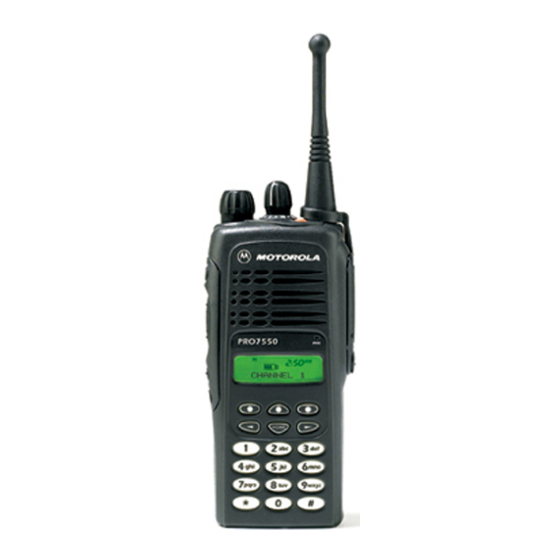
PARTS OF THE RADIO RADIO OVERVIEW ™ ™ PRO7550 and PRO7650 Models Mode Selector Knob Top Button (D) On/Off/Volume Knob (programmable) Side Button 1 (A) LED Indicator (programmable) (Select Key) Push-to-Talk (PTT) Microphone Button Front Buttons Side Button 2 (B) -
Page 16: On/Off/Volume Knob
On/Off/Volume Knob Push-to-Talk (PTT) Button Turns the radio on or off, and adjusts the radio’s Press and hold down this button to talk; release it to volume. listen. Mode Selector Knob With PTT Released (radio receiving) Selects the required operation mode. Blinking red Mode busy (conventional LED Indicator... - Page 17 These keys are used for: • dialing a phone number. • entering a specific radio ID number when mak- ing a private or Call Alert radio call The following table shows the character cycle for each key, when entering information for programming the radio’s lists.
-
Page 18: Menu Keys
• When editing existing information, pressing Softkeys (l;l) would ALWAYS start the character When already in Menu Mode, these keys are used cycle at the “ blank space ” and NOT at “1”. to make Menu selections. Menu Keys Left and Right Arrow Keys (,/) Softkey 3 Softkey 1 Softkey 2... -
Page 19: Menu Display
HOME Key (.) LCD Screen and Icons The HOME key will always return you to the home (default) display. In most cases, this is the current A B C F G J mode. In addition, if you are using a feature that “K P requires it, pressing the HOME key will also cause information to be saved in memory before going to... -
Page 20: Alert Tone Indications
Symbol Name and Description Symbol Name and Description Carrier Squelch Indicator Programming/Viewing Mode Indicates when the active conventional Indicates when the radio is in the pro- mode is being monitored in the carrier gramming or viewing mode; squelch mode; ON = IN VIEWING MODE ON = BEING MONITORED/ BLINKING = IN PROGRAMMING OFF = NOT BEING MONITORED. - Page 21 • Unsuccessful Power-Up – A short, low-pitched • Invalid (Bad) Key Press – A short, low-pitched tone when the radio is first turned on indicates tone when a keypad key is pressed indicates that the radio has failed its power-up self test that the key press was rejected.
-
Page 22: Programmable Buttons
• Call Alert™ (Page) Sent – A single medium- Programmable buttons include: pitched tone (central acknowledge), followed by • The three Side Buttons (A, B, C) and the Top a group of four medium-pitched tones indicates Button (D) that a Call Alert page sent by your radio has •... - Page 23 Check with your dealer for a complete list of features your radio supports. Button Short Press Long Press Hold Down Monitor/Perma- Temporarily monitors the Continually monitors Monitors the selected nent Monitor selected channel for any activity. the selected channel. channel for any activity. Volume Set —...
-
Page 24: Trunked Radio Systems
TRUNKED RADIO SYSTEMS • No channel monitoring required prior to trans- mission. PRO7550 and PRO7650 radios can operate on both • Improved system access. Privacy Plus™ trunked and conventional radio • Automatic channel selection. systems. Conventional typically refers to radio-to-radio •... -
Page 25: Getting Started
GETTING STARTED LED Color Status BATTERY INFORMATION Battery in rapid-charge Steady Red mode. Charging the Battery Battery in charger, not in rapid- f a battery is new, or its charge level is very low, you Flashing Yellow charge mode but waiting to be will need to charge it before you can use it. -
Page 26: Battery Charge Status
Battery Charge Status Battery chargers will only charge the Motorola- authorized batteries listed below; other batteries If programmed by your dealer, you can check your may not charge battery’s charge status by holding down the preprogrammed Battery Gauge button. The charge status is shown by the color of the radio’s LED... -
Page 27: Attaching The Battery
Attaching the Battery Removing the Battery Battery Latches Turn off the radio (see page 30). Fit the extensions at the bottom of the bat- tery into the bottom slots on the radio. Slide both battery latches downward. Press the top part of the battery toward the Pull the top part of the battery away from radio until you hear a click. -
Page 28: Accessory Information
ACCESSORY INFORMATION Removing the Antenna Attaching the Antenna Turn the antenna counterclockwise to Turn the antenna clockwise to attach it. remove it. English... -
Page 29: Attaching The Belt Clip
Attaching the Belt Clip Removing the Belt Clip Belt Clip Tab Use a key to press the belt clip tab away Align the grooves of the belt clip with those from the battery. of the battery. Slide the belt clip upward to remove it. Press the belt clip downward until you hear a click. -
Page 30: Attaching The Side Connector Cover
Attaching the Side Connector Cover Turning The Radio On or Off Antenna Loop Slot Thumbscrew RECEIVING A TRUNKED CALL Place the loop (attached to the side con- nector cover) over the antenna; then slide it downward until it touches the top of the Turn your radio on. -
Page 31: Radio Self Test
Turn the radio off, check the battery, and turn the radio back on. If the radio still does not pass the self check, a problem exists in the radio. Contact your nearest Motorola Service Shop. Note: The power-up self check verifies that the radio’s microprocessor-based systems are... - Page 32 Notes English...
-
Page 33: Radio Calls (Trunked Operation Only)
This section outlines the basic functions of your radio. / until ZONE is All references to what is shown on the display is only displayed. valid for PRO7550/PRO7650 radios. Throughout this ZONE MUTE CALL section, the display below l (the softkey For example below ZONE ). -
Page 34: Selecting A Mode
Selecting a Mode MAKING A CALL Turn the Mode Selector knob to the desired Conventional Modes mode. Turn the radio on and select the desired The display shows For example conventional zone and mode (see Selecting the selected mode’s a Zone and Mode ). name. -
Page 35: Trunked Modes
Trunked Modes Coded Squelch Operation Tone Private-Line® (PL), Digital Private-Line™ (DPL), Turn the radio on and select the desired and carrier squelch operation are all available in your trunked zone and mode (see Selecting a radio, on a per-mode basis. Zone and Mode ). -
Page 36: Muting The Keypad Tones
on a conventional mode. When the trunked system Press the softkey returns to normal operation, the radio will below the desired automatically leave the failsoft operation and return mute state (on or to trunked operation. off). The radio PLANT POLICE During failsoft operation, returns to the home display. -
Page 37: Scan
All references to what is shown on the display does not have autoscan enabled. is only valid for PRO7550/PRO7650 radios. Throughout this section, the display below Turning Scan On or Off with the Keypad) / until SCAN is displayed. -
Page 38: Deleting Nuisance Modes
Viewing a Scan List Press the softkey below the desired PLANT POLICE The view scan list feature allows you to view the scan state (on or off). members of the scan list associated with the currently The radio returns to selected mode. -
Page 39: Programming A Scan List
The programming-mode annunciator, K, Note: , or / to select the required zone. If is displayed while list view mode is active. the scan status annunciator G is displayed, the mode is part of the scan list. The scan status annunciator, G, appears, •... - Page 40 Notes English...
-
Page 41: Trunked Features
If your radio has been so programmed, you radio. All references to what is shown on the display can press the call button for quick access is only valid for PRO7550/PRO7650 radios. to viewing your radio’s ID number. This Throughout this section, the display below takes you directly to step 3. -
Page 42: Answering A Private Call
Answering a Private Call If you decide to answer the call, press the PTT button. Upon receiving a Private Alternates between The caller’s ID number Conversation call, two CALL remains displayed for alert tones sounds the duration of the call. ID: 722588 (repeating every five seconds for 20 sec-... -
Page 43: Making A Private Call
Making a Private Call 4b On the display, the old ID number disappears and the new digits appear as they are being There are four phases in making a private call, entered. namely: 4c The cursor flashes indicating the location of •... - Page 44 Sending the Radio ID Number 4c If there are 10 or more members in the list, the display shows “ID LOC#X_” (where X is Press the PTT button to transmit the ID num- the first digit). The cursor blinks to show the ber.
- Page 45 ™ Having the Conversation and Hanging-up Leaving a Call Alert Page Press the PTT button to have a Private Con- If the party you want to have a Private Call versation with the called person. does not answer the call within twenty sec- onds, you can choose to leave a Call Alert™...
-
Page 46: Call Alert Operation
™ ™ CALL ALERT OPERATION Making a Call Alert ™ There are three phases in making a call alert, Answering a Call Alert Page with a Group namely: Call • initiating a call alert, Upon receiving a Call Alert page, four alert tones sounds (repeats every 5 seconds). - Page 47 Entering the Radio ID Number that you tional press of this key causes the last Wish to Page member of the preprogrammed call list to be displayed; pressing / shows the first If the last ID number called or member of the list. received is the desired number, go To enter a number from the call list directly to step 5.
-
Page 48: Sending The Call Alert
Sending the Call Alert 4c. If there are 10 or more members in the list, the display shows “ID LOC#X_” (where X is Press the PTT button to transmit the ID num- the first digit). The cursor blinks to show the ber. -
Page 49: Programming The Radio'slists
PROGRAMMING THE RADIO’S Alternates between When you stop on a LISTS member of the list, the POLICE DEPT Programming the Telephone List Numbers display will alternate between showing the This feature lets you use the radio’s keypad to change member’s name and the telephone numbers assigned to any of the 5556213 telephone number. -
Page 50: Programming The Call List
• You can only enter a maximum of 16 digits 10. When you have finished changing the tele- in any entry for the telephone list. When phone number, press the select key again. this maximum is reached, the cursor will The change is saved in the radio’s memory. - Page 51 l (the softkey below A long press would CALL ). The display enable the editing of the shows the first program- member’s name. The GIBERTO mable member of the display shows the cur- call list. rent member’s name. / or , 10.
-
Page 52: Trunked Telephone Operation
The programming-mode annunciator, K, Note: Answering a Telephone Call blinks while program mode is active. When a telephone call is Alternates between In the edit mode, the , key functions as • being received, you will a backspace key. Pressing it will erase the PLANT POLICE hear telephone-type previous numeric digit, and the cursor will... -
Page 53: Making A Telephone Call
Making a Telephone Call Sending the Telephone Number Sending the telephone number using the There are three phases in making a phone call, keypad namely: • accessing the telephone system, 6a. The number can now be entered from the keypad, using any of the numeric (0 – 9) •... - Page 54 Sending the telephone number using a num- Sending the telephone number using a location in the ber on the telephone list telephone list , or /, to enter the telephone list. , or /, to enter the telephone list. / takes you forward to the next member of 6b.
- Page 55 1 of this button again to send out the extension number. procedure. • Motorola trunked radios generate a high-pitched • If you are out of range of the trunked system or go-ahead tone when the systems PTT button is the phone interconnect is out of service, “NO...
-
Page 56: Automatic Multiple Site Selection (Amss) (Pro7650 Only)
AUTOMATIC MULTIPLE SITE Locking and Unlocking a Site SELECTION (AMSS) (PRO7650 / until SITE is dis- ONLY) SITE PAGE CALL played. l (the softkey below SITE ). Note: This feature is only available in the PRO7650 model. Availability of this The current lock state is feature is limited to customers operat- momentarily displayed. -
Page 57: Conventional Call
To send a conventional call CONVENTIONAL CALL Hold the radio in a vertical posi- tion at a distance of about 1 to 2 This section outlines the conventional features of your inches (2.5 to 5 cm) from your radio. . mouth. -
Page 58: Smart Ptt
• If the repeat/direct feature is programmed to the When smart PTT is enabled in your radio, you cannot keypad, you can change the repeat/direct setting transmit on an active mode. Three radio-wide by doing the following. variations of smart PTT are available. / until DIR is dis- •... -
Page 59: Warranty
One (1) Year warrant the installation, maintenance or service of the Product. Motorola, at its option, will at no charge either repair the Product (with new or MOTOROLA cannot be responsible in any reconditioned parts), replace it (with a new... - Page 60 COMMERCIAL LOSS, LOST PROFITS warranty. Because each system which may OR SAVINGS OR OTHER INCIDENTAL, use the Product is unique, MOTOROLA SPECIAL OR CONSEQUENTIAL disclaims liability for range, coverage, or DAMAGES ARISING OUT OF THE USE...
- Page 61 Product of non-Motorola warranty service location. Warranty service supplied equipment) which adversely affect will be provided by Motorola through one of performance of the Product or interfere with its authorized warranty service locations. If Motorola's normal warranty inspection and you first contact the company which sold...
- Page 62 MOTOROLA with such claim; respect to infringement of patents by the Product B) that MOTOROLA will have sole control of the or any parts thereof. defense of such suit and all negotiations for Laws in the United States and other countries its settlement or compromise;...
- Page 63 Motorola software. MOTOROLA software may be used in only the Product in which the software was originally embodied and such software in such Product may not be replaced, copied, distributed, modified in any way, or used to produce any derivative thereof.
- Page 64 Notes English...
-
Page 65: Accessories
CHARGERS ACCESSORIES AAHTN3000_ 110V Single-Unit Rapid Charger, US Plug Motorola offers a number of accessories to enhance the productivity of your two-way radio. Many of the AAHTN3001_ 230V Single-Unit Rapid Charger, Euro available accessories are listed below. For a Plug complete list, see your Motorola dealer. -
Page 66: Remote Speaker Microphones
BATTERIES RMN4054 Receive Only Hard Hat Mount Headset, Gray - Noise Reduction HNN9008_R Small NiMH, High-Capacity RMN4055 Receive Only Headband Style Headset HNN9009_R Large NiMH, Ultra-High-Capacity with 3.5mm right angle plug HNN9010_R Large NiMH, Ultra-High-Capacity FM RKN4097 In-Line PTT Adapter Cable (for use with HNN9011_R Large NiCd, High-Capacity FM RMN4051, RMN4052, RMN4053 Head-... -
Page 67: Antennas
ANTENNAS 136 - 174 MHz, Ferrule Connector PMAD4012_ VHF 136–155 MHz 9 cm, Stubby PMAD4013_ VHF 155–174 MHz 9 cm, Stubby PMAD4014_ VHF 136–155 MHz 14 cm, Standard Length REd Code PMAD4015_ VHF 155–174 MHz 14 cm, Standard Length Black Code HAD9743_ VHF 162–174MHz, Stubby PMAD4023_... - Page 68 Notes English...
- Page 69 Answering a Telephone Call Press the preprogrammed phone button or call response button to answer the call. ™ ™ PRO7550 PRO7650 Quick Reference Card ™ Answering a Call Alert Page with a Group Call Record the functions for your radio’s programmable buttons in the table provided below.