Advertisement
Table of Contents
- 1 Table of Contents
- 2 Safety Precautions
- 3 Importance Administering Point on the Safety
- 4 Important for Laser Products
- 5 Preventing Static Electricity
- 6 Disassembly Method
- 7 Adjustment Method
- 8 Flow of Functional Operation
- 9 Maintenance of Laser Pickup
- 10 Replacement of Laser Pickup
- 11 Description of Major Ics
- 12 Block Diagram
- Download this manual
See also:
Instruction Manual
SERVICE MANUAL
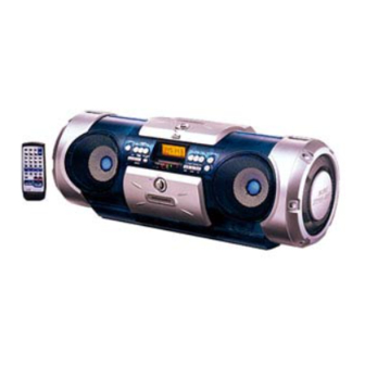
CD PORTABLE SYSTEM
TIMER
ON/OFF
CLOCK
TIMER
SLEEP
DOWN
UP
SET
PROGRAM
RANDOM
AUTO
PRESET
REPEAT
TUNER
AUX
C D
TAPE
BAND
FM MODE
REVERSE MODE
REW
FF
MULTI CONTROL
DISPLAY
SOUND
ACS
AHB PRO
VOLUME
RM-RXVB55
REMOTE CONTROL
This service manual adds UY version to the service manual
(RV-B550BU No.20826) previously issued.
Contents
Safety precautions ...................................1-2
Importance administering
point on the safety ............. 1-3
Important for laser products .................... 1-4
Preventing static electricity ...................... 1-5
Disassembly method ............................... 1-6
RV-B550BU
Supplement
This service manual is made from 100% recycled paper.
COPYRIGHT
2001 VICTOR COMPANY OF JAPAN, LTD.
UY ................ Argentina
Adjustment method ................................. 1-15
until TOC read ................. 1-19
Maintenance of laser pickup .................... 1-20
Replacement of laser pickup ....................1-20
Description of major ICs .......................... 1-21~29
RV-B550BU
Area Suffix
No.20826C
Jan. 2001
Advertisement
Table of Contents

Related Manuals for JVC RV-B550BU


Summary of Contents for JVC RV-B550BU
-
Page 1: Table Of Contents
VOLUME RM-RXVB55 REMOTE CONTROL Area Suffix UY ....Argentina This service manual adds UY version to the service manual (RV-B550BU No.20826) previously issued. Contents Adjustment method ......... 1-15 Safety precautions ........1-2 Flow of functional operation Importance administering until TOC read ....1-19 point on the safety ..... -
Page 2: Safety Precautions
RV-B550BU Safety precautions 1. This design of this product contains special hardware and many circuits and components specially for safety purposes. For continued protection, no changes should be made to the original design unless authorized in writing by the manufacturer. -
Page 3: Importance Administering Point On The Safety
RV-B550BU Importance administering point on the safety Note : It's means "J" for U.S.A. and Canada market model. RV-B550J ONLY RV-B550J SEULEMENT Full Fuse Replacement Marking Marquage Pour Le Remplacement Complet De Fusible Graphic symbol mark Le symbole graphique (Ce symbole signifie (This symbol means fast blow type fuse.) -
Page 4: Important For Laser Products
RV-B550BU Important for laser products 5.CAUTION : If safety switches malfunction, the laser is able 1.CLASS 1 LASER PRODUCT to function. 2.DANGER : Invisible laser radiation when open and inter 6.CAUTION : Use of controls, adjustments or performance of lock failed or defeated. Avoid direct exposure to beam. -
Page 5: Preventing Static Electricity
RV-B550BU Preventing static electricity 1. Grounding to prevent damage by static electricity Electrostatic discharge (ESD), which occurs when static electricity stored in the body, fabric, etc. is discharged, can destroy the laser diode in the traverse unit (optical pickup). Take care to prevent this when performing repairs. -
Page 6: Disassembly Method
RV-B550BU Side grille (left) Disassembly method <Main Body> Removing the side grilles (See Fig.1 and 2) Remove the six screws A attaching the side grille on the left side of the body and pull out the side grille from the body. -
Page 7: Rv-B550Bu
RV-B550BU CN406 Removing the cassette mechanism CN405 assembly (See Fig.4 and 5) Prior to performing the following procedure, remove the right and left side grilles and the front cabinet assembly. Disconnect the card wires from connector CN405 and CN406 on the microcomputer board located on the underside of the CD unit of the rear cabinet assembly. -
Page 8: Rv-B550Bu
RV-B550BU Microcomputer board Removing the tuner board (See Fig.9) CN403 Antenna wire Prior to performing the following procedure, remove the right and left side grilles, the front cabinet assembly. Disconnect the card wire from connector CN403 on the microcomputer board. -
Page 9: Rv-B550Bu
RV-B550BU <CD unit assembly> Key switch board Removing the microcomputer board (See Fig.12 and 13) Disconnect the card wire from connector CN251 and CN252 on the key switch board on the front side of the CD unit assembly. Remove the four screws J attaching the microcomputer board on the underside of the CD unit assembly. -
Page 10: Rv-B550Bu
RV-B550BU CD door switch Removing the CD door switch board board (See Fig.16) Prior to performing the following procedure, remove the microcomputer board. Release the two tabs d fixing the CD door switch board on the back of the CD unit assembly. -
Page 11: Rv-B550Bu
RV-B550BU <Front Cabinet Assembly> Removing the LED boards (See Fig.20) Prior to performing the following procedure, remove FW261 the front cabinet assembly and the rear cabinet Speaker Speaker assembly. FW251 Remove the two screws N and two screws O attaching the LED boards on the speaker. -
Page 12: Rv-B550Bu
RV-B550BU <<Cassette mechanism section>> Cassette mechanism Removing the playback/recording & eraser head ( See Figs. 1 and 2 ) 1. While shifting the trigger arms seen on the right side of the head mount in the arrow direction, Flywheel R... -
Page 13: Rv-B550Bu
RV-B550BU Removing the head amplifier & mechanism control P.C. board (See Fig. 4) Belt 1. Remove the cassette mechanism assembly. Main motor 2. After turning over th cassette mechanism assembly, assembly remove the three screws A retaining the head amplifier & mechanism control P.C. board. -
Page 14: Rv-B550Bu
RV-B550BU Removing the flywheel (See Figs. 7 and 8) Flywheel R Flywheel L 1. Remove the head amplifier & mechanism control P.C. board. 2. Remove the main motor assembly. 3. After turning over the cassette mechanism, remove the slit washers b and c fixing the capstan shafts R and L, and pull out the flywheel R and L respectively from behind the cassette mechanism. -
Page 15: Adjustment Method
RV-B550BU Adjustment method Tuner section Measuring devices necessary for adjustment 1. Low-frequency oscillator Voltage input to the tuner ......+B: DC 5.7 V VT: DC 12 V It must have the ability to output 600ohm from 0 dBs Standard measuring output ..26.1 mV (0.28 V) /3ohm at an oscillation frequency of 20 Hz 50 Hz. -
Page 16: Rv-B550Bu
RV-B550BU Location of parts to be adjusted Cassette handling mechanism Cassette handling mechanism (reverse side) Head for recording, playing and erasing the tape Head azimuth adjusting Head azimuth adjusting screw (fast-forward) screw (rewind) CN31 Head for recording, Head azimuth adjusting... - Page 17 RV-B550BU Adjustment of cassette handling mechanism Items Condition Method for adjustment Standard Parts to be and confirmation value adjusted Confirmation Test tape: VT-703 (10 kHz) (1) Play back the VT-703 test tape. Maximum Adjust the of head angle Measuring output terminal:...
- Page 18 RV-B550BU Standard values for confirmation of electronic performance Items Condition Method for adjustment Standard Parts to be and confirmation value adjusted Erasing Fast-forward and Load the test tape (AC-514 for TYPE II, TYPE II: 110 current rewind direction: AC-225 for TYPE I) into the tape...
-
Page 19: Flow Of Functional Operation
RV-B550BU Flow of functional operation until TOC read Check Point Slider turns REST Power Key Power ON Check that the voltage at the pin 5 SW ON. of CN602 (or pin 5 of IC901) is 0V (a moment)? Automatic tuning... -
Page 20: Maintenance Of Laser Pickup
RV-B550BU Maintenance of laser pickup Replacement of laser pickup (1) Cleaning the pick up lens Befor you replace the pick up, please try to Turn off the power switch and,disconnect the clean the lens with a alcohol soaked cotton power cord from the ac outlet. -
Page 21: Description Of Major Ics
RV-B550BU Description of major ICs AN8806SB (IC601) : RF&Servo AMP 1.Terminal Layout PDAC PDBD LDON PDER PDFR TBAL RF OUT FBAL RF IN C.AGC EF OUT C.ENV TE OUT C.EA CROSS CS BDO TE BPF VDET CS BRT LD OFF... - Page 22 RV-B550BU 3. Functions Pin No. Symbol Functions and operations APC amp input terminal APC amp output terminal LD ON APC ON/OFF control terminal Connect to ground Power supply Inverse input pin for RF amp RF OUT RFamp output RF IN...
- Page 23 RV-B550BU BA6897FP-W (IC602) BA15218N (IC801/IC831) : 4channel driver : Dual op amplifier D.BUF BA15218N CH1-OUTA D.BUF CH1-OUTB CH4-OUTA D.BUF CH1-INA Level CH4-OUTB Level shift shift D.BUF CH1-INB CH4-INA +IN1 OUT2 Vcc OUT1 -IN1 VEE +IN2 -IN2 T.S.D TEST1 CH4-INB TEST2...
- Page 24 RV-B550BU BH3852S (IC501) : E.Volume 1.Block diagram (BASS) (TREBLE) TONE CONTROL CONTROL (BASS) (TREBLE) TONE CONTROL 2.Pin function Function Function Pin No. Pin name Pin No. Pin name Terminal for bass control Grand terminal BASS Terminal for treble control Terminal for 1ch volume input...
- Page 25 RV-B550BU LC72136N(IC2):PLL Frequency synthesizer 1. Layout FM/AM LPFOUT LPFIN CLOCK FM/ST/VCO FMIN AM/FM AMIN IFCONT SDIN IFIN 2. Block Phase Reference Detector Driver Charge Pump Swallow Counter Swallow Counter 1/16,1/17 4bit 1/16,1/17 4bit Unlock Detector 12bit Programmable DriverS Universal Data Shift Register & Latch...
-
Page 26: Block Diagram
RV-B550BU BA44W12ST-V5/Z1(IC310):Regulator TA78DL06S(IC390) : Regulator INPUT – OUT1 SHORT PROTECTION OUTPUT OVER VOLTAGE/ THERMAL SHUT – DOWN PROTECTION – OUT2 GP1U281X(IC903) : Remocon sensor – Limiter Integrator Comparator B.P.F Demodulator Amp. Vout TA2008AN (IC 1): FM/AM,IF/DET Block diagram IF OUT IF REQ... - Page 27 RV-B550BU MN35510(IC603):DIGITAL SERVO&DIGITAL SIGNAL PROCESSER 1. Terminal Layout 20 ~ 41 ~ 2.Block Diagram LRCKIN(MSEL) AVSS1 8TIMES BCLK(SSEL) AVDD1 DIGITAL OVER SAMPUNC SRDATAIN OUTR DEEMPHSIS DIGITAL FILTER 1BIT (PSEL) LOGIC IOSEL CLVS BLKCK OUTL CLDCK SBCK SUBC DEMPH RESY FLAG6(RESY)
- Page 28 RV-B550BU 3. Description symbol I/O Description symbol I/O Description BCLK Not used Tracking error shunt signal output(H:shunt) LRCK Not used PLAY Not used SRDATA WVEL Not used Not used DVDD1 Power supply (Digital) RF signal input DVSS1 Connected to GND...
- Page 29 RV-B550BU BA15218F-XE(IC401/751):OP AMP. OUT1 -IN1 OUT2 +IN1 -IN2 +IN2 1-29...
- Page 30 RV-B550BU VICTOR COMPANY OF JAPAN, LIMITED AUDIO DIVISION,10-1,1Chome,Ohwatari-machi,Maebashi-city,371-8543,Japan Printed in Japan (No.20826C) 200101 (V )