Table of Contents
Advertisement
Quick Links
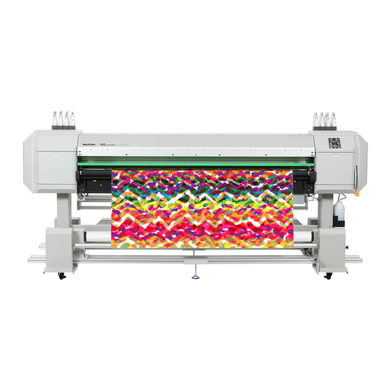
VJ-1938TX
Operation Manual
Operations and Maintenance Methods
• Unauthorized copying or duplication of the whole or part of the contents of this manual is prohibited.
• Every care has been taken in writing the contents of this manual, but please contact MUTOH or the dealer you purchased the
product from if you find any unclear, erroneous or otherwise unsatisfactory content in the manual.
• Please be aware that MUTOH will not be liable in any way for failures or accidents that result from handling or operating the
printer according to any procedures other than those set forth in this manual.
• Company names and product names that appear in this manual are registered trademarks of the respective companies.
Advertisement
Table of Contents

Related Manuals for MUTOH VJ-1938TX


Summary of Contents for MUTOH VJ-1938TX
- Page 1 • Please be aware that MUTOH will not be liable in any way for failures or accidents that result from handling or operating the printer according to any procedures other than those set forth in this manual.
-
Page 2: Warranty Limitations
Warranty Limitations • MUTOH INDUSTRIES LTD. warrants part repair or replacement as a sole measure only if a failure is found in the system or in the materials and workmanship of the product the seller produced. -
Page 3: Table Of Contents
Contents Chapter 1 Basic Operations Introduction ..............9 Name of each part . - Page 4 Chapter 2 Advanced Operations Introduction ..............63 Operating the keys to use the menus .
- Page 5 Menu 7: Display ............. 98 Display 1: Language .
- Page 6 Chapter 4 Appendix Messages and Error Messages ..........138 Status messages .
- Page 7 Chapter 1 Basic Operations Introduction ........... . . 9 Name of each part .
- Page 8 What you can do during printing ....... .57 Pausing/Restarting printing ........... . 57 Canceling printing .
-
Page 9: Introduction
Introduction Introduction Name of each part Printer’s main body Front cover Open and close this cover when media is loaded or jammed. It is normally closed. Maintenance cover L Operation panel Maintenance cover R ⇒Operation panel P. 10 Open and close this cover when Open and close this cover cleaning or replacing consumables. - Page 10 Network connector Power connector Connect an Ethernet cable. mini DIN connector Connect the external heater control cable to this port. Do not connect the cable through the rear roller. Ink color indicating labels Ink color indicating labels Cartridge slots Cartridge slots Install an ink cartridge or cleaning cartridge.
-
Page 11: Operation Panel
Operation panel Power button Error indicator ・ Pressing this turns the power on. ・ Lights up in orange when an error Lights steady in blue when the has occurred or a cover is open. ・ Flashes when the ink is low. power is on. - Page 12 Take-up System Take-up Unit Front roll unit (driven) Front roll unit (drive) Mount the paper tube to Mount the paper tube to take up the media. take up the media. Front tension unit Operation switch Tension roller ⇒Operation switch With the tension bar, you can (Take-up System) P.13 set the media using the tension take-up method.
- Page 13 Operation switch (Take-up System) Take-up Unit Error lamp Operation lamp Lights up or blinks red to Lights up green when the indicate an error. power is on. During the operation, it blinks. AUTO switch Sets the media rolling MANUAL switch method.
-
Page 14: Menu Chart
Menu chart Setting menu 1 to Setting Menu 3 Menu 1 : Setup > Set 1: User Type to Setting Menu 4 Set 2: Spitting Set 3: Side Margin to Setting Menu 4 Set 4: Media Initial セット4: Set 5: メディアケンシュツ... -
Page 15: Setting Menu
Setting menu 2 from Setting Menu 1 Menu 2 : Test Print > Test 1 : Nozzle Check Test 2 : Mode Print Test 3 : Setup List Test 4 : Palette セット4: Test 5 : HeadAdjust > メディアケンシュツ HeadAdj. 1 : Standard HeadAdj. - Page 16 Setting menu 3 Set 1 : User Type User : Type 1 Mode : Graphics 2 - > * *> 1 : Print Mode Effect : Fine & Fog * *> 2 : Adjust Print > 170 µm Thickness : Adj.
- Page 17 Setting menu 4 Spitting : Pass Count : X cnt Set 2 : Spitting Spitting : On Media Pass Count : X cnt Spitting : Off Set 4 : Media Initial Init : Off Init : Width InkDryTimer : XX min Output Mode : Off...
- Page 18 Setting menu 5 Media Kind : Off Set 14 : Media Length Media Kind : Media 1 Media Kind : Media 2 Length : 30 m Media Kind : Media 3 Exhaust Fan : Off Set 15 : Exhaust Fan Exhaust Fan : Exhaust Fan : High...
- Page 19 Menu during printing Menu 1 : PF Micro Adj. Menu 2 : Backup Menu 3 : Job Status ToDoLength : XXX.X mm Done : XXX.X mm Remain : XXX.X mm Remain Time : XXXX min Menu chart...
-
Page 20: System Configurations Of This Product
Main functions: • Status monitor • Remote panel ValueJet Club server Connect to the ValueJet Club. https://valuejetclub.mutoh.co.jp/mutoh/guser Internet *1 ValueJet Club VSM Mobile This Web service provides free useful contents to ValueJet users. Status check and remote control Have user registration done to use various services. -
Page 21: Connecting To A Computer
Connecting to a Computer Connect the Ethernet cable to the product. Connect the Ethernet cable to the computer. Use the printer operation panel to set the IP address, subnet mask and gateway. 「Set 20: IP Address」 P. 「Set 21: Subnet Mask」 P. 「Set 22: Gateway」... -
Page 22: Launching/Displaying/Finishing Valuejet Status Monitor (Vsm)
Right click somewhere the [Start] screen tiles are not displayed to display the application bar, and click [All Apps]. • Windows7/ Windows Vista From the [Start] menu, click [All Programs] (or [Programs]) - [MUTOH] - [ValueJet Status Monitor]. Displaying VSM Double click the VSM icon in the task tray. -
Page 23: Printing Area
Finishing VSM Right click the VSM icon in the task tray, and click [Exit]. Note When using normally, do not finish VSM. When closing the VSM window, click [Settings] - [Close]. Windows8.1 Click the Down Arrow in the [Start] screen. Click [ValueJet Status Monitor]. -
Page 24: Requirements For Usable Media
Requirements for usable media Media that meet the requirements below can be used with this printer. Usable sizes Maximum 1,910 mm width Minimum 900 mm width Maximum 3.5 mm (When the head height is set to High) thickness Weight 100 kg or less Important! The default setting for the head height is Low. -
Page 25: Cautions In Using This Product
Cautions in using this product Please use this product periodically It is recommended to use this product once a week. When left unused for a long time, the print head nozzles can get cloggedcausing damage. Conduct periodic maintenance This product requires daily maintenance. •... -
Page 26: How To Use The Ink Gutter
How to use the ink gutter How to use the ink gutter This product comes with an ink gutter. The ink gutter is a groove for collecting the ink that permeates through the media during the printing operation. Inside the gutter, there is a sponge (ink gutter filter). -
Page 27: Take-Up System
Take-up System Take-up System Take-up Methods With this product, there are 2 methods for setting roll media. Use the method that is suitable for the media. • Tension take-up method Use the tension unit to apply load and take up the media. By applying the right amount of load, you can prevent the prints from getting creased or misaligned. -
Page 28: Operation
Operation 「Loading the media」 P. 38 For details on how to set the media, see Feeding the media after cutting Press and hold the [ - ] key on the operation panel. • The media will be fed. Press! Rolling back the media during the media setting operation Raise Media setting lever. - Page 29 When the red lamp lights up Set the AUTO switch on the side where the red lamp has lit up to OFF. OUTSIDE ROLL INSIDE ROLL Set the AUTO switch according to the media rolling direction. OUTSIDE ROLL INSIDE ROLL When "Media End/Take-up Error"...
- Page 30 Press the [Enter] key on the operation panel. • Media detection will start. Press! Operation...
-
Page 31: Adjusting The Weight
Adjusting the Weight To print on the roll media using an appropriate tension, adjust the tension unit weight before loading the media. • An appropriate tension: When the slack is taken up from the media. However, for the stretchable media, it should not be stretched too much. - Page 32 Pull the weight changing pin to check that it does not come off. Note If it is difficult to insert the pin in the weight, try holding up the tension bar slowly. Adjusting the tension unit weight (when removing the pin) While pressing the button for the weight changing pin, remove the pin from the weight changing hole.
-
Page 33: Adjusting The Rail
Adjusting the Rail If the media is wrinkled when wound, the rail may not be parallel to the printer. Adjust the rail. The adjusting method is the same for the front rail and rear rail. Adjust both the front and rear rails. Adjusting the Rail (Adjusting the Path Length) Use a hexagonal wrench (commercial product), and loosen two screws (hexagon socket head cap screw M4 ×... - Page 34 Rotate the rail adjusting screws on left and right sides, and adjust so that the lengths of the media edges are the same on both sides. Tighten the screw that you loosened in step 1. Adjust the Feeding Unit in the same way. Adjusting the Rail...
-
Page 35: Adjusting The Slack Detection Sensor
Adjusting the Slack Detection Sensor The angles of the slack detection sensor and sensor reflector may not be aligned after adjusting the rails. In the following case, adjust the angle of the slack detection sensor: • If only the green lamp of the slack detection sensor turns on when the take-up unit is turned on. (In a normal case, the orange and green lamps turn on at the same time.) Note If there are any objects between the slack detection sensor and sensor reflector, remove them and check the above item. -
Page 36: Powering On / Off
Powering ON / OFF Powering ON / OFF Printer Turning the power ON Close the front cover. Press the power button of this product to turn the power ON. • The blue light becomes ON. Press! • This product starts its initialization operations. Turning the power OFF Make sure printing is done. -
Page 37: Take-Up System
Take-up System Turning the power ON Press the power button of the Take-up System to turn the power ON. • The green light becomes ON. Turning the power OFF Make sure printing is done. Press the power button of the Take-up System to turn the power OFF. •... -
Page 38: Loading The Media
Loading the media Loading the media There are two methods for loading the roll media to this printer. Use the appropriate method depending on the media you are using. Important! Depending on the type of the media, we recommend that 2 or more persons set the media. Tension take-up method You can apply the load using the tension unit to take up the roll media. - Page 39 When the media setting lever is lowered, lift it up. Turn on the Take-up System. Switch the rear roll unit AUTO switch depending on the media you are setting. OUTSIDE ROLL • INSIDE ROLL: When setting the inside roll media. •...
-
Page 40: Put The Media Through The Rear Roller Assembly
Loosen the screws with a handle on left and right sides, and then adjust the position of the roll media. • Make sure that the center of the roll media and the center of the media feed slot are aligned. •... - Page 41 Put the roll media from the bottom to the top over the rear roller (B). Put the roll media from the bottom to the top over the rear roller (C). The media should be loaded to the roller as shown in the illustration when seen from the side.
-
Page 42: Loading The Media To The Take-Up Unit
Loading the media to the Take-up Unit Move the MANUAL switch on the rear tension unit to the NORMAL side and NORMAL pull the roll media out about 1.5 m. Let the media that you pulled out drop in front of you. Place the media setting plate in the center of the media. - Page 43 Pull out the media setting plate from the front side. Pull the media out several times until it reaches a length of about 1 m. Note • If you continue pulling the media longer than a certain amount of time, the red lamp on the rear tension unit will light up. The rear tension unit will stop.
- Page 44 Using the tension take-up method to set the media Lift the tension bar of the front tension unit manually to its highest position. Remove the auxiliary media setting plate from hook A and place it on hook B. • Mount the tension bar to the auxiliary media setting plate. Put the roll media from the bottom to the top over the front tension unit's tension bar.
- Page 45 • For the inside roll media Remove the auxiliary media setting plate from hook B and place it on hook A. Loading the media to the Take-up Unit...
-
Page 46: After Loading The Media
Using the slack take-up method to set the media (Only outside roll media) Drop the roll media between the tension bar of the front tension unit and the media tube. w v u Secure the roll media to the media tube using double-sided tape. Note •... -
Page 47: After Loading The Media
After loading the media... Set the media holder at both edges of the media. w v u Important! With the default settings, the printing operation starts 5 mm from the edge of the media. To hold down the media, make sure that the part overlapping the media is less than 5 mm in length. - Page 48 Open the ink gutter cover. w v u Note If the ink gutter cover isn't completely open, you cannot print. Close the front cover. w v u Turn the power of the printer on. Press! After loading the media...
- Page 49 Using the printer operation panel • "No Media Detected" is displayed on the operation panel. • Press and hold the [Enter] key to 2 seconds or longer to execute media initialization. Press! Make sure that the [Take-Up] lamp has lit up green. Check! Note If the [Take-Up] lamp is not green, select "Take Up"...
-
Page 50: Nozzle Check And Cleaning
Nozzle check and cleaning Nozzle check and cleaning Before starting everyday operation, please check the nozzle. If nozzle clog is found, conduct cleaning. Nozzle check Nozzle check steps Load the media for Nozzle check. 「Loading the media」 P. 38 Press the [Menu] key. Press! •... -
Page 51: Cleaning
Cleaning Cleaning steps Press the [Cleaning] key, so that the “Normal” indicator (one of the “Cleaning Mode” indicators) lights steady. Press! • The cleaning mode will be set to “Normal”. Give the [Cleaning] key a long press, for 2 seconds or more. •... -
Page 52: Setting The Printing Precision
Setting the Printing Precision Setting the Printing Precision Before starting to print for the first time, adjust the printing precision. Head adjustment You can print out the adjustment pattern in this menu to check the misalignment of the print head, and then adjust it. Adjustment methods for this printer are as follows. -
Page 53: Print Quality Adjustment
Head adjustment steps Turn the printer and the Take-up System ON and load the media. 「Loading the media」 P. 38 Press the [Menu] key. Press! • Press the [ - ] key several times, to bring up the display on the left. Menu2 :... -
Page 54: Print Quality Adjustment
Print quality adjustment It is used for optimizing the quality of image prints. Adjustment methods for this printer are as follows. Adjusts only the print mode used by the current user definition. When you have adjusted the print mode using Standard, make the resolution, pass Adj. -
Page 55: Media Feed Adjustment
Print quality adjustment steps Turn the printer and the Take-up Unit ON and load the media. 「Loading the media」 P. 38 Press the [Menu] key. Press! • Press the [>] key. Menu 1: Setup > • Press the [Enter] key. Set 1: User Type •... -
Page 56: Media Feed Adjustment
Media feed adjustment This adjustment is necessary when: • you use this product for the first time. • you change the type of the media. 「Nozzle check」 P. 50 In other cases, proceed to For this adjustment, you need a ruler. Use a commercially available ruler. Note If you encounter any of the following problems with the printing results, you may be able to solve them by adjusting the media feed. - Page 57 • Press the [ - ] key several times, to bring up the display on the left. * *> 3 : PF Adjust > • Press the [>] key. • Use the [+]/[ - ] key to select a menu. PF 1 : Initial Print •...
-
Page 58: What You Can Do During Printing
What you can do during printing What you can do during printing Pausing/Restarting printing To halt printing, press the [Cancel] key. • The printing pauses. • To resume printing, press the [Enter] key. Press! Note • In this operation, printing data sent to the product are not deleted. •... - Page 59 Menu 1: PF Micro Adjustment With this menu item, you can alter the micro-adjustment value for the feed correction. The alteration will be valid for the current printing only. • See the following related sections of Panel Setting Menus (Chapter 2 below): 「** >...
- Page 60 Menu 3: Job Status This menu item displays data on the job being printed. • See the following related sections of Panel Setting Menus (Chapter 2 below): 「Menu 8: Job Status」 P. 100 Press the [Enter] key. Menu 3 : Job Status Use the [+] / [ - ] key to select a menu item.
- Page 61 Chapter 2 Advanced Operations Introduction ........... . 63 Operating the keys to use the menus .
- Page 62 Menu 5: Version ..........97 Menu 6: Sleep Mode .
-
Page 63: Introduction
Introduction Introduction The panel setting menus can be used to carry out various kinds of settings for the printer. Operating the keys to use the menus To access the panel setting menus, press the [Menu] key. Push Note The panel setting menus cannot be accessed during printing or while data is being received (the power button is flashing). -
Page 64: Panel Setup Menu
Panel setup menu Menu 1: Setup Various settings of the printer are configured. Menu 1: Setup > Submenus Set 1: User Type Set 1: User Type Set 2: Spitting Set 2: Spitting Set 3: Side Margin Set 3: Side Margin Set 4: Media Initial Set 4: Media Initial... - Page 65 Menu 1: Setup Set 23: Header Dump Set 23: Header Dump Set 24: Single Head Set 24: Single Head Set 25: Start Feed Set 25: Start Feed Set 26: Temporary Set 26: Temporary Menu 2: Test Print Performs nozzle check of the print head and setup list. Menu 2: Test Print >...
- Page 66 Menu 5: Version Displays the versions of the firmware. Menu 5: Version > Submenus Version: X.XX Menu 6: Sleep Mode Configures or activates the sleep mode. Menu 6: Sleep Mode > Submenus Sleep Mode 1: Set Timer SleepMode 1 : SetTimer Sleep Mode 2: Start SleepMode 2 :...
-
Page 67: Menu 1: Setup
Menu 1: Setup Menu 1: Setup Set 1: User Type The User Type are is a kind of pre-settings for printing. You can have up to 15 groups of User Type, labeled “Type1” to “Type15”. When Set 1: User Type you select a User Type group (“Type”) and press the [Enter] key, that definition group will be set for the printer. - Page 68 **>1: Print Mode Making settings for print mode * *> 1 : Print Mode • Pressing the [>] key while a mode is displayed will bring up detailed information on that mode (resolution, number of passes, print direction), which will be displayed for as long as the key is held down. •...
- Page 69 Effect Sets up the Effect menu. Mode : Quality 1 - > Set up this menu when you want to improve print quality by adjusting the set print mode. Setting values The Effect function is not used. Effect : None The printing joint will be the wave form.
- Page 70 Adj. Print 2: Custom Perform adjustment for all patterns (A to F). Adj. Print 2 : Custom 「1. Confirm pattern」 P. 71 「2. Rough adjustment pattern」 P. 72 「3. Fine adjustment pattern」 P. 72 Submenus The test patterns of A to F will be printed for Adj.
- Page 71 Steps Print a confirm pattern and check it for printing errors. Print "Rough adjustment pattern" and look for a place that is properly adjusted in the printing results of print head 1. • If you selected "Adj. Print 2: Custom", select "ALL" or "A" to "F". •...
- Page 72 2. Rough adjustment pattern • Press the [Enter] key to carry out printing. For the Rough adjustment pattern, the same patterns will be printed on both sides and center of the media. • For Head 1, check the print results on both sides and center of the media and select the number that looks most aligned between 1 and 21.
- Page 73 ** > 3: PF Adjust Sets up various settings on the Media feed correction. * *> 3 : PF Adjust > When the following defects are found in printing results, they may improve by conducting a media feed correction. • Images are overlapping. •...
- Page 74 Refer to Chapter 1 「Media feed adjustment steps」 P. 56 and select "PF4: Micro Print" on the operation panel. • Check the pattern and micro change value. • In the pattern, look for a place that has least white lines or overlapping in images. The number printed below the adequate pattern is the micro change value.
- Page 75 PF2: Initial Change Use the [+] / [ - ] key to enter the adjustment value, and press the [Enter] key. PF2 : Initial Change Setting values You can set a value that is between +50 mm Init. : 250.0 mm / 250 mm and -50 mm of the feed length configured in "Initial Print".
- Page 76 PF4: Micro Print Pressing the [Enter] key when the words on the left are displayed will execute micro PF4 : Micro Print adjustment printing. • Observe the pattern and verify the micro change value. • In the pattern, look for a place that has least white lines or overlapping in images. The number printed below the pattern is the micro change value.
- Page 77 ** > 4: Thickness Sets the thickness of the media you are using. * *> 4 : Thickness Use the [+] / [ - ] key to enter the value, and press the [Enter] key. Setting values 80 μm to <170 μm> to 3500 μm Thickness : 170 µm <>...
-
Page 78: Set 2: Spitting
Set 2: Spitting Sets up the spitting operation while printing. Set 2: Spitting The display will shift to setting of the pass count only if “On” is set for “Spitting”. Setting values Perform the spitting operation on Spitting box Spitting : located on the origin side for every shuttle. -
Page 79: Set 3: Side Margin
<Example of spitting operation> Spitting setting Pass Count setting Operation 1 cnt Perform the spitting operation on Spitting box every time Print head returns to the origin position. Spitting operation is not performed over the media. 5 cnt Performs the spitting operation on Spitting box on the origin side every five times Print head returns to the origin position. -
Page 80: Set 5: Media Width
Set 5: Media Width Sets the width of the current media when the Media Initial menu is set to "Off". Set 5: Media Width Use the [+] / [ - ] key to enter the value, and press the [Enter] key. When the Media Initial menu is set to "Width", the detected media width will be displayed. -
Page 81: Set 7: Origin
Set 7: Origin Sets the beginning of printing (origin) of the print data. Set 7: Origin Set the menu when reprinting on the margin with changing the printing data position to the printed media. Use the [+] / [ - ] key to enter the value, and press the [Enter] key. Setting values X (media feeding distance): X (PF) :... -
Page 82: Set 9: Multi Strike
Set 9: Multi Strike Sets up the overwrite count per line. Set 9: Multi Strike Use the [+] / [ - ] key to enter the value, and press the [Enter] key. Setting values <1 time> to 9 times Strike Cnt : 1 cnt <>... -
Page 83: Set 12: Auto Cleaning
Set 12: Auto Cleaning Configure the settings for the auto cleaning operation. Set 12: Auto Cleaning Submenus Auto 1: Waiting Time Auto 1 : WaitingTime Auto 2: Printing Time Auto 2 : PrintingTime Auto 3: Before Print Auto 3 : Before Print Auto 1: Waiting Time For setting whether auto cleaning will be carried out before printing. -
Page 84: Set 13: Ink Status
Set 13: Ink Status The amount of ink remaining in each Ink cartridge is displayed. (unit: %) Set 13: InkStatus Setting values • K: K1 (Black) KkCc: XX / XX / XX / XX • k: K2 (Black) • C: C1 (Cyan) MmYy: XX / XX / XX / XX •... -
Page 85: Set 15: Exhaust Fan
Set 15: Exhaust Fan Sets up Exhaust fan operation. Set 15: Exhaust Fan Ventilates the inside of the printer to stabilize the parts performance. It also decreases the contamination by ink mist inside the printer. We recommend that you use Exhaust fan, especially when printing for a long time. Setting values Turn Off Exhaust fan. -
Page 86: Set 18: Initialization
• The part should be changed when all of the asterisks have disappeared and "Change" is displayed. Contact your local MUTOH dealer to ask for replacing parts. • After “Change” appears, “Life Times [Head]” or a similar message will be displayed when you are not in this menu. -
Page 87: Set 20: Ip Address
Set 20: IP Address Sets the IP address of the printer. Set 20: IP Address • Use the [+] key to increase a setting value. • Use the [ - ] key to decrease a setting value. • Press the [Enter] key to confirm your input for a value. The cursor will move on to the next setting value. -
Page 88: Set 23: Header Dump
Set 23: Header Dump Sets whether to print the following information when printing. Set 23: Header Dump • Data header • Data dot number (printed only when Header damp setting is ON) • Printer serial number • Firmware version Setting values Dump data is not printed. -
Page 89: Set 25: Start Feed
Set 25: Start Feed You can change the margin setting between images. Set 25: Start Feed • Value over 0: The margin setting between images will be wider than when setting "0". • Value equal to 0: The default margin setting between images will be applied. •... -
Page 90: Menu 2: Test Print
Menu 2 : Test Print Menu 2: Test Print Test 1: Nozzle Check It is used to check whether there are any clogged heads, or missing or blurred prints. Test 1 : Nozzle Check 「Nozzle check」 P. 50 Print Head 2 Print Head 1 Print Head 1 Print Head 2... -
Page 91: Test 3: Setup List
Setup List Setup List <Information> 2016/01/01 0:00 Serial No. = ********** !Error! Model = VJ-1938TX Firmware = V 1.00 0 : None [ ] 2 : None [ ] 4 : None [ ] Memory Size = 384MB 1 : None [ ]... -
Page 92: Test 5: Head Adjust
Test 5: Head Adjust There are 2 print heads installed in the carriage of this product. Test 5 : HeadAdjust > In this menu, you can align the print head 1 and print head 2 in order to prevent the prints [>] from being misaligned. - Page 93 Fine patterns for each print mode Print Mode Print mode specifications Adjustment pattern Quality 1 1440 x 1440, 16 pass, Uni Quality 2 1440 x 1440, 16 pass, Bi Quality 3 720 x 1440, 8 pass, Uni Quality 4 720 x 1440, 8 pass, Bi Graphics 1 720 x 1080, 6 pass, Uni Graphics 2...
-
Page 94: Menu 3: Cleaning
Menu 3 : Cleaning Menu 3: Cleaning Perform Head cleaning. Consumes less ink than Normal cleaning. Time : Short Conduct nozzle check before and after printing, and use when nozzle clogging is found. Time : Normal Consumes more ink than Normal cleaning. When nozzle clogging still occurs after Normal Time : Long cleaning, conduct Long cleaning. -
Page 95: Menu 4: Menu Option
Menu 4 : Menu Option Menu 4: Menu Option You can choose whether to display the menus in "Menu 1: Setup". Choose whether you wish to display a menu by pressing the [Enter] key. [*]= the item will be displayed [ ]= the item will not be displayed Displays the "User Type"... - Page 96 Displays the "Exhaust Fan" menu. 15: [*] Exhaust fan The initial value is [*]. Displays the "Longstore" menu. 16: [*] LongStore The initial value is [*]. Displays the "CR Maintenance" menu. 17: [*] CR Maintenance The initial value is [*]. Displays the "Initialization" menu. 18: [*] Initialization The initial value is [*].
-
Page 97: Menu 5: Version
Menu 5 : Version Menu 5: Version Displays the versions of the firmware. Version : X.XX Menu 6 : Sleep Mode Menu 6: Sleep Mode Sleep Mode 1: Set Timer This is for setting the interval at which head cleaning will be carried out in the sleep mode. Sleep Mode 1 : SetTimer Setting values... -
Page 98: Menu 7: Display
Menu 7 : Display Menu 7: Display Display 1: Language For setting the language that will be displayed. Display 1: Language Setting values Displays will be in English. Language : エイゴ This is the initially set value. Displays will be in Japanese. Language :... -
Page 99: Display 4: Remain Ink
Display 4: Remain Ink For setting whether to display the ink level indicator. Display 4: Remain Ink Setting values Remaining ink icons will be displayed. Remain Ink : On Remaining ink icons will not be displayed. Remain Ink : Off This is the initially set value. -
Page 100: Menu 8: Job Status
Menu 8 : Job Status Menu 8: Job Status Displays if the print is completed. JobStatus : Completed • When the print is completed: [Completed] • When the print is canceled: [Canceled] The total length of print data (media feeding direction) will be displayed. ToDoLength : XXX.X m The printed length will be displayed. - Page 101 Chapter 3 Maintenance Maintenance ..........102 Checking ink and replacing ink cartridge .
-
Page 102: Maintenance
When not used for a long period Important! Since a service technician has to handle following cases, please contact your local MUTOH dealer. • Error requiring restart is happening repeatedly. • The message to notify the life of print head and various motors is displayed. -
Page 103: Checking Ink And Replacing Ink Cartridge
Checking ink and replacing ink cartridge Checking ink and replacing ink cartridge Checking ink level Press the [Menu] key on the operation panel. Press! Press the [>] key. Menu 1 : Setup > Press the [ - ] key several times, to bring up the display on the left. Set13 : InkStatus Press the [Enter] key. -
Page 104: Replacing Ink
Replacing ink When ink level becomes low, the error LED of the operation panel flashes and a buzzer sounds. Also, [Ink End] is displayed on the operation panel. Promptly replace the ink. If the ink is not replaced within a certain period after [Ink End] is displayed on the operation panel, printing temporarily stops. In this case, replace the ink with new ink to restart printing. - Page 105 Installing the ink pack and smart chip card Open the new ink pack, and shake it as instructed below. 3 sec. • Turn the ink plug upward and wait for 3 seconds. • Next, turn the ink plug downward and wait for 3 seconds. •...
- Page 106 Installing the high-capacity pack adapter Insert the high-capacity pack adapter. • Match the colors of the label on the printer and the label on the high-capacity pack adapter. • Firmly insert it all the way in. Note Place the used ink pack in a plastic bag or the like and dispose of it in accordance with local ordinances and municipal instructions. Replacing ink...
-
Page 107: Emptying Waste Fluid Tank
Emptying waste fluid tank Emptying waste fluid tank Emptying waste fluid tank In the following cases, move the waste ink in the waste fluid tank into a container to discharge it. • When Waste fluid tank is more than half full •... - Page 108 Wipe the opening of Waste fluid valve with a cloth, etc. Dispose of the waste fluid as an industrial waste product. WARNING You are obligated to properly dispose of waste fluid from the printer in compliance with Wastes Disposal and Public Cleansing Act and local ordinances.
-
Page 109: Cleaning Each Part
Cleaning each part Cleaning each part To use this product always in its best condition, please clean periodically. Head cleaning When nozzle clogging is found in nozzle check, conduct head cleaning. Head cleaning consumes ink. There are several cleaning modes in this product. Please use them accordingly based on your usage condition. Short cleaning Consumes less ink than Normal cleaning. - Page 110 Give the [Cleaning] key a long press, for 2 seconds or more. • Cleaning will start. Press! Conduct Nozzle Check. • If nozzle clogging still remains, repeat cleaning and nozzle check. 「Steps for head cleaning」 P. 109 Note • When nozzle clogging remains even after repeating normal cleaning several times, conduct Long cleaning. 「Cleaning of cleaning wiper」...
-
Page 111: Cleaning Of Cleaning Wiper
Cleaning of cleaning wiper Cleaning period: • Weekly • When print blurring and dot missing remain after head cleaning is done. Preparation: • Cleaning stick Important! During cleaning, please note the followings. • If it is hard to remove the stain, perform “Short” Head cleaning, and then clean again. •... -
Page 112: Cleaning The Cleaning Wiper
Cleaning the cleaning wiper Open the maintenance cover on the right side. Detach the maintenance cover. Wipe the cleaning wiper with a cleaning stick. • Wipe the left side surface of cleaning wiper going back and forth. Important! If it is hard to remove the stain, perform “Short” Head cleaning, and then clean again. - Page 113 Wipe the right side surface of the base of cleaning wiper going back and forth. Attach the maintenance cover. Close the maintenance cover. Press the [Enter] key. CR Mainte. : The message on the left will appear. CR Mainte. : Start •...
-
Page 114: Cleaning Of Print Head Circumference
Cleaning of print head circumference Cleaning period: • Weekly • When print blurring and dot missing remain after head cleaning is done. Preparation: • Cleaning stick Important! During cleaning, please note the followings. • Use a cleaning stick in dry condition. If moisten with water or solution, it can cause damage to the print head. •... - Page 115 Look at the bottom side of the carriage and check if dusts and ink lump are adhered. Circumference of Print head • Print head circumference (silver metal part) • Print head guide part (black plastic part) Head guide If dusts or ink lump are adhered, clean with a cleaning stick. Do not touch the print head surface Important! •...
-
Page 116: Inside Cleaning
Inside cleaning Cleaning period: • Monthly • When dust or ink stains are visible Preparation: • Soft cloth CAUTION Unplug the power cable with the power off, before cleaning the inside of the printer. Steps Remove the media. Confirm that the power for the printer and the take-up system is off. Open the front cover. - Page 117 Close the front cover. Inside cleaning...
-
Page 118: Maintaining The Ink Gutter
Maintaining the ink gutter Check and clean the ink gutter regularly. WARNING When cleaning the gutter, be sure to turn off the power and remove the power plug from the outlet. Cleaning the ink gutter filter Before cleaning the ink gutter filter: •... - Page 119 Connect the waste liquid tube to the waste liquid container. Open the ink gutter cover. • Put some water into the bottle. • Pour the water into the ink gutter filter to wash off the ink. WARNING If foreign substances or liquids such as water entered the printer, do not use the printer as it is. It could lead to an electric shock or fire.
- Page 120 Cleaning inside the ink gutter Cleaning period: • Once a week while the ink gutter filter is cleaned (This depends on how frequently you use the printer. Check the ink gutter regularly) Preparation: • Plastic gloves (commercially available) • Soft cloth (commercially available) •...
- Page 121 Put the ink gutter filter back in its place. • Firmly insert the ink gutter filter frame into the gutter. Important! If the ink gutter filter frame is not in its place, the print head strike or print head damage may occur. Close the ink gutter cover.
- Page 122 Remove the ink gutter filter and its frame (x 4). Pull out the plug on the waste liquid tube of the gutter. • The waste liquid tube is located on the lower left side of the printer. Connect the waste liquid tube to the waste liquid container. Wash the gutter with water.
- Page 123 Put the plug back into the waste liquid tube. Put the ink gutter filter back in its place. • Firmly insert the ink gutter filter frame into the gutter. Important! If the ink gutter filter frame is not in its place, the print head strike or print head damage may occur. [10] Close the ink gutter cover.
-
Page 124: Cleaning The Take-Up System
Cleaning the Take-up System Cleaning period: • When ink stains are visible Preparation: • Soft cloth CAUTION Unplug the power cable with the power off, before cleaning the inside of the printer. Steps Unload the media. Make sure that the printer and the Take-up System are turned OFF. Use a wet, tightly-wrung soft cloth to clean the tension rollers of the Take-up Unit. -
Page 125: Replacing Consumable Parts
Replacing consumable parts Replacing consumable parts Replacing absorption material for the flushing box The flushing box is a part that keeps receiving ink discharged from the print head. Please replace the absorption material for the flushing box periodically. If used without replacing, it can cause damage to the print head. Replacing period: •... - Page 126 Close the maintenance cover. Replacing steps Put the printer into the CR maintenance mode. 「Putting the printer into the CR maintenance mode」 P. 111 「Cleaning of cleaning wiper」 under Open the front cover. Cover the platen with the paper you can get dirty. Important! Ink may drip from the absorption material for the flushing box.
- Page 127 Attach new absorption material for the flushing box. Close the front cover. Press the [Enter] key. CR Mainte. : The message on the left will appear. CR Mainte. : Start • That ends the procedure. Replacing absorption material for the flushing box...
-
Page 128: Replacing The Ink Gutter Filter
Replacing the ink gutter filter Periodically replace the ink gutter filter. CAUTION Unplug the power cable with the power off, before replacing the ink gutter filter. Replacing period: • Ink gutter filter need to be replaced when ink stain cannot be removed after cleaning. Preparation: •... - Page 129 Remove the ink gutter filter and its frame (x 4). • Remove the dirty ink gutter filter from the frame. • Attach the new ink gutter filter. Note Place the used ink gutter filter in a plastic bag and dispose of it in accordance with your local regulations. Put the ink gutter filter back in its place.
-
Page 130: Moving Or Transporting The Printer
Moving or transporting the printer Moving or transporting the printer This section describes how to move or transport the printer. Moving the printer This section describes how to move the printer. Important! • When moving the printer, make sure to maintain a horizontal position. •... -
Page 131: Transporting The Printer
When transporting the printer, make sure to pack it in the same condition as purchased, using protective and packing materials to protect the printer from vibration and shocks. Important! When transporting the printer, consult the MUTOH product dealer at your point of purchase. Transporting the printer... -
Page 132: Long-Term Storage
Long-term storage If not using the printer for a long time, execute [Longstore]. Empty the waste fluid tank. 「Emptying waste fluid tank」 P. 107 Press the [Menu] key. Press! Press the [>] key. Menu 1 : Setup > Press the [ - ] key several times, to bring up the display on the left. Set 16 : Longstore Press the [Enter] key. - Page 133 Install the cleaning cartridges to all of the ink cartridge slots. • The arrow should face up. • Insert all the way to the end. The message on the left will appear. Busy-Washing • Charging of the cleaning fluid begins. When charging of the cleaning fluid is complete, the message to the Remove Cartridges left is displayed.
- Page 134 [10] Remove all cleaning cartridges. The message on the left will appear. Busy-Washing • Discharging of cleaning fluid begins. When discharging is complete, the message to the left is displayed. [ALL] No Cartridge [11] Turn the power off. Long-term storage...
-
Page 135: Performing Initial Charging After Head Cleaning
Performing initial charging after head cleaning Turn the power button of this product ON. Press! • Blue light becomes ON. • The product starts initialization operations. When the message to the left is displayed, press the [Enter] key. Start Ink Charge ->... - Page 136 Insert High-capacity pack adapters. • Match the label of this product to the color label of High-capacity pack adapters. • Insert all the way to the end. The message on the left will appear. Ink Refill • Ink charging begins. When ink charging is complete, the message to the left is displayed.
- Page 137 Chapter 4 Appendix Messages and Error Messages ........138 Status messages .
-
Page 138: Messages And Error Messages
(** represents the set User type.) Life Times [Head *] The operational life of the print head has almost expired. (Continues operation) Contact your local MUTOH dealer. Life Times [Pump] The operational life of the pump motor has almost expired. (Continues operation) Contact your local MUTOH dealer. - Page 139 Display Description [*] Change Plug Connector rubber for High-capacity pack adapter is at the end of its life. Replace Connector rubber of High-capacity pack adapter. Operation manual for High-Capacity Ink Pack Adapter S/C Reading Reading the S/C card. *** Remote Mode *** The remote panel mode is running, via VSM or similar.
-
Page 140: Error Message Display And Remedies
Error message display and remedies This section describes error messages and remedies. Error messages are displayed when certain failures occur during printer operation. If an error that can be displayed occurs, the printer may display the following error messages on the operation panel and stop operation. - Page 141 Ink cartridges are inserted in wrong slots. Insert ink cartridges correctly again. [*] S/C Ink Err The ink cartridge cannot be used for this printer. Contact your local MUTOH dealer. [*] S/C CodeErr Inserted ink cartridge is not a proper one. Contact your local MUTOH dealer.
-
Page 142: Error Requiring Restart
For an error requiring restart, operation will return to normal after removing the cause of the error and restarting the printer. If the same error continues to be displayed, contact the your local MUTOH dealer. Be sure to tell us the code no. of the error message when you contact us. -
Page 143: Specifications Of This Product
Specifications of this product Drawing area *1*2 a=5mm b=5mm c=5mm d=5mm *1 After media initial, printing starts at 15 mm. *2 While the media initial tip is ON, printing starts at 40 mm. *3 According to the remote panel settings Possible drawing area Drawing area... -
Page 144: List Of Specifications
List of specifications Model Name VJ-1938TX Print method On demand piezo method Drive method Firmware servo/DC motor drive Media feed method Grid roller system Media fixing system Pressurization roller down system by manual lever Conditions of usable Maximum width 1,910 mm... - Page 145 Current consumption 100V to 120V 2.5 A or below 200V to 240V 1.0 A or below External dimensions Height 1,261 mm (Size of printer when the front cover is opened: 1,529 mm) Width 2,983 mm Depth 1,134 mm Weight Main body 177 kg Stand 37 kg...
- Page 146 Take-up System Drive method DC Geared Motor Drive Condions of usable Maximum width 1,910 mm media Minimum width 900 mm Outside diameter of the roll Less than Φ250mm media Media Core Dimension 50.8 mm(2 inch), 76.2 mm(3 inch) Supported Media Core 2,000 mm Width Roll media weight...
- Page 148 VJ1938TXE-A-00...