Table of Contents
Advertisement
Quick Links
Advertisement
Table of Contents

Related Manuals for Taurus XE330-C09


Summary of Contents for Taurus XE330-C09
- Page 1 XE330-C09...
-
Page 2: Safety Hints
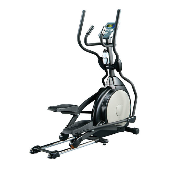
SAFETY HINTS WARNING - Read all instructions before using this appliance. ■ Do not operate elliptical on deeply padded, plush or shag carpet. Damage to both carpet and elliptical may result. ■ Keep children away from the elliptical. There are obvious pinch points and other caution areas that can cause harm. - Page 3 INTRODUCTION Console Handle Bar Handpulse Drink Bottle Holder Console Mast Console Mast Cover Pedal Wheel Connecting Arm Pedal Arm Rear Stabilizer Cover Cushion (Foot Pad)
-
Page 4: Assembly Pack Check List
ASSEMBLY PACK ASSEMBLY PACK CHECK LIST CHECK Step 1 LIST #78. M5 x 10m/m #70. 5/16" x 15m/m #102. 5/16"x 23 x2T #97. 5/16"x 23 x1.5T Phillips Head Screw (4pcs) Hex Head Screw (6pcs) Curved Washer (2pcs) Flat Washer (4pcs) * these four screws are attached in the back of the console. - Page 5 ASSEMBLY PACK ASSEMBLY PACK CHECK LIST CHECK Step4 LIST #79. M5 x 15m/m #84. ψ3.5x12m/m Phillips Head Screw (8pcs) Self Tapping Screw (8pcs) Tools #108. Combination M5 Allen Wrench & Phillips Head Screw Driver (1 pc) #110. 12m/m Wrench ( 1pc) #111.
- Page 6 ASSEMBLY DRAWING Step 1...
- Page 7 ASSEMBLY DRAWING Step 2...
- Page 8 ASSEMBLY DRAWING Step 3...
- Page 9 ASSEMBLY DRAWING Step 1...
-
Page 10: Unpacking The Unit
ASSEMBLY Assembly ■ UNPACKING THE UNIT 1. Using a razor knife (Box Cutter) cut the outside, bottom, edge of box along the dotted Line. Lift Box over the unit and unpack. 2. Carefully remove all parts from carton and inspect for any damage or missing parts. If damaged parts are found, or parts are missing, contact your dealer immediately. -
Page 11: Step 3: Connecting Arm Assembly
ASSEMBLY STEP 3: CONNECTING ARM ASSEMBLY 1. Align the hole in the end of the Connecting arms (L&R)(7&8)(pivoting rod end) with the hole in the bracket of the Lower Handle Bars (L&R)(3&4). The rod end should be on the inside of the Lower Handle Bars (L&R)(3&4). bracket. Take 2pcs of 5/16" x 1-1/4" Hex Head Screws (71) and install it through the Lower Handle Bars (L&R)(3&4) bracket and the rod end. - Page 12 LUBRICATION & TRANSPORT ■ ■ ■ ■ LUBRICATION 1. Pour 2c.c of the lubricant under the middle of Rail. You must be pour lubricant each three months. 2. If the user felt the exercise is not smooth or there were some noise during exercising, please pour 2 c.c.of the lubricant on the middle of Rails.
-
Page 13: Quick Start
FUNCTIONS COMPUTER OPERATION INSTRUCTIONS Starting a program Quick Start After the console power on you must to set date and time by rotating Enter key, then press Enter key to confirm. After finishing the installation time you may press the Start key to begin, this will initiate the Quick Start mode. -
Page 14: Preset Programs
FUNCTIONS Manual After power up, or reset, highlight the Manual icon at the bottom of the display and press Enter key. The profile will be blinking and you may rotate the Enter key to adjust the program workload and then press Enter. - Page 15 FUNCTIONS If you want to choose to work at 75% - for example - then use the Enter arrow to highlight 75% and press Enter. Now the Time window will be blinking and you can program it and other data the same as other programs.
- Page 16 WARM UP Quadriceps Stretch With one hand against a wall for balance, reach behind you and pull your right foot up. Bring your heel as close to your buttocks as possible. Hold for 15 counts and repeat with left foot up. Inner Thigh Stretch Sit with the soles of your feet together with your knees pointing outward.
-
Page 17: Weight Training
AEROBIC EXERCISE Aerobic exercise is any sustained activity that sends oxygen to your muscles via your heart and lungs. Aerobic exercise improves the fitness of your lungs and heart - your body’s most important muscle. Aerobic exercise fitness is promoted by any activity that uses your large muscle -arms, legs, or buttock, for example. - Page 18 OVERVIEW CHART...
- Page 19 PARTS LIST DESCRIPTION O'TY Main Frame Pedal Arm (L) Pedal Arm (R) Lower Handle Bar (L) Lower Handle Bar (R) Bushing Housing, Pedal Arm Connecting Arm (L) Connecting Arm (R) Cross Bar Console Mast Idler Wheel Assembly Crank Axle Swing Arm (L) Swing Arm (R) Rail Tube Rail Strap...
- Page 20 PARTS LIST DESCRIPTION O'TY Round Disk Round Disk Cover Cover Swing Arm Axle Pedal Arm Cover (L) Pedal Arm Cover (R) Pedal (L) Pedal (R) Slide Wheel Cover Button Head Plug Front Handle Bar Cover (L) Rear Handle Bar Cover (L) Front Handle Bar Cover (R) Rear Handle Bar Cover (R) Round Cap...
- Page 21 PARTS LIST DESCRIPTION O'TY 3/8" × 7T_Nyloc Nut 3/8" -UNF26 × 4T_Nut 3/8" -UNF26 × 9T_Nut 3/8" × 7T_Nut M12_Nut 3/8" × 19 × 1.5T_Flat Washer 5/16" × 35 × 1.5T_Flat Washer 5/16" × 23 × 1.5T_Flat Washer 5/16" × 20 × 1.5T_Flat Washer 1/4"...