Table of Contents
Advertisement
Advertisement
Table of Contents

Related Manuals for Fluke 9100S


Summary of Contents for Fluke 9100S
- Page 1 Hart Scientific 9100S Dry-Well Calibrator User’s Guide Rev. 811601...
- Page 2 Fluke Corporation, Hart Scientific Division 799 E. Utah Valley Drive • American Fork, UT 84003-9775 • USA Phone: +1.801.763.1600 • Telefax: +1.801.763.1010 E-mail: support@hartscientific.com www.hartscientific.com Subject to change without notice. • Copyright © 2005 • Printed in USA Rev. 811601...
-
Page 3: Table Of Contents
Table of Contents 1 Before You Start ......1 Symbols Used ......1 Safety Information . - Page 4 Scan ....... . . 22 7.3.1 Scan Control ........22 7.3.2 Scan Rate .
- Page 5 12.2.1 EMC Directive ....... . . 42 12.2.2 Low Voltage Directive (Safety) ......42...
- Page 6 Back Panel ....... . 13 Figure 2 Side View of the 9100S Showing the Prop Stand ... . 14 Figure 3 Front Panel .
- Page 7 Tables Table1 International Electrical Symbols ..... 1 Table 2 Controller Communications Commands ....33 Table 2 Controller Communications Commands continued .
-
Page 8: Before You Start
1 Before You Start Symbols Used Before You Start Symbols Used Table 1 lists the International Electrical Symbols. Some or all of these symbols may be used on the instrument or in this manual. Table1 International Electrical Symbols Symbol Description AC (Alternating Current) AC-DC Battery... -
Page 9: Safety Information
9100S Dry-well Calibrator User’s Guide Symbol Description Canadian Standards Association OVERVOLTAGE (Installation) CATEGORY II, Pollution Degree 2 per IEC1010-1 re- fers to the level of Impulse Withstand Voltage protection provided. Equipment of OVERVOLTAGE CATEGORY II is energy-consuming equipment to be supplied from the fixed installation. - Page 10 1 Before You Start Safety Information ing power such as storage in a low humidity temperature chamber operat- ing at 50 degree centigrade for 4 hours or more. • DO NOT use this instrument for any application other than calibration work.
-
Page 11: Cautions
9100S Dry-well Calibrator User’s Guide • DO NOT connect this instrument to a non-grounded, non-polarized out- let. Ensure the earth ground to the outlet is properly connected. Electrical shock may result if the outlet is not installed correctly. • Always replace the power cord with an approved cord of the correct rat- ing and type. -
Page 12: Authorized Service Centers
Authorized Service Centers Please contact one of the following authorized Service Centers to coordinate service on your Hart product: Fluke Corporation, Hart Scientific Division 799 E. Utah Valley Drive American Fork, UT 84003-9775 Phone: +1.801.763.1600 Telefax: +1.801.763.1010... - Page 13 9100S Dry-well Calibrator User’s Guide Phone: +86-10-6-512-3436 Telefax: +86-10-6-512-3437 E-mail: xingye.han@fluke.com.cn Fluke South East Asia Pte Ltd. Fluke ASEAN Regional Office Service Center 60 Alexandra Terrace #03-16 The Comtech (Lobby D) 118502 SINGAPORE Phone: +65 6799-5588 Telefax: +65 6799-5588 E-mail: antng@singa.fluke.com...
-
Page 14: Introduction
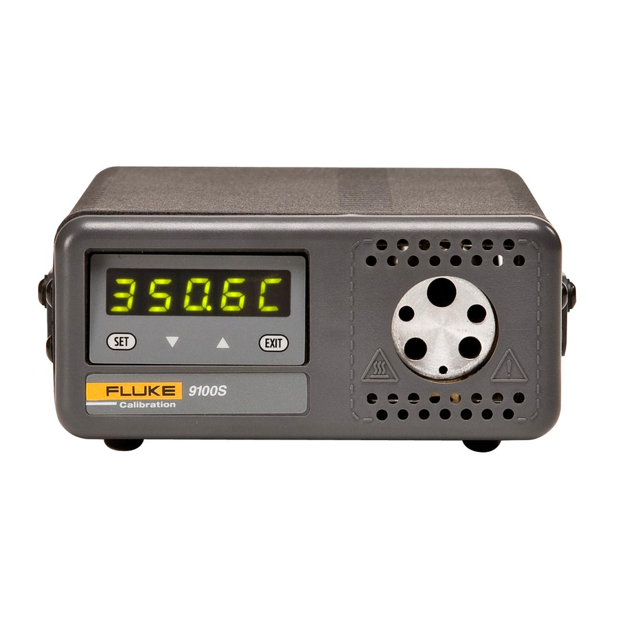
2 Introduction Introduction The Hart Scientific 9100S Mid-Range Field Calibrator may be used as a porta- ble instrument or bench top temperature calibrator for calibrating thermocouple and RTD temperature probes. This instrument is small enough to use in the field, and accurate enough to use in the lab. Calibrations may be done over a range of 35°C to 375°C (95°F to 707°F). -
Page 15: Specifications And Environmental Conditions
3 Specifications and Environmental Conditions Specifications Specifications and Environmental Conditions Specifications Range 35°C to 375°C (95°F to 707°F) Accuracy ±0.25°C at 50°C ±0.25°C at 100°C ±0.5°C at 375°C Stability ±0.07°C at 50°C ±0.1°C at 100°C ±0.3°C at 375°C Resolution 0.1°C or °F Well-to-Well Uniformity ±0.2°C with sensors of similar size at equal depths within wells Heating Times 35 to 375°C: 9.5 minutes... -
Page 16: Warranty
• indoor use only Warranty Fluke Corporation, Hart Scientific Division (Hart) warrants this product to be free from defects in material and workmanship under normal use and service for a period as stated in our current product catalog from the date of shipment. -
Page 17: Quick Start
Unpack the dry-well carefully and inspect it for any damage that may have oc- curred during shipment. If there is shipping damage, notify the carrier immediately. Verify that the following components are present: • 9100S Dry-well • Power Cord • User's Guide with Report of Calibration • RS-232 Cable •... -
Page 18: Setting The Temperature
9100S Dry-well Calibrator User’s Guide Setting the Temperature Section 7.2 explains in detail how to set the temperature set-point on the cali- brator using the front panel keys. The procedure is summarized here. (1) Press “SET” twice to access the set-point value. -
Page 19: Parts And Controls
5 Parts and Controls Rear Panel Parts and Controls The user should become familiar with the dry-well calibrator and its parts: (See Figures 1, 2, and 3). Rear Panel Power Cord - The removable power cord, (Figure 1) attaches to the back side of the instrument. -
Page 20: Side View
The prop stand can be swung down into a standing position when using the in- strument at an inclined position. Figure 2 Side View of the 9100S Showing the Prop Stand... -
Page 21: Front Panel
100.0C EXIT 9100S Figure 3 Front Panel Setting the control temperature is done directly in degrees of the current scale. It can be set to one-tenth of a degree Celsius or Fahrenheit. -
Page 22: Constant Temperature Block Assembly
9100S Dry-well Calibrator User’s Guide EXIT – Used to exit a function and to skip to the next function. Any changes made to the displayed value are ignored. Constant Temperature Block Assembly The “Block” is made of aluminum and provides a relatively constant and accu- rate temperature environment in which the sensor that is to be calibrated is in- serted. -
Page 23: General Operation
6 General Operation Setting the Temperature General Operation Setting the Temperature Section 7.2 explains in detail how to set the temperature set-point on the cali- brator using the front panel keys. The procedure is summarized here. (1) Press “SET” twice to access the set-point value. (2) Press u or d to change the set-point value. -
Page 24: Controller Operation
7 Controller Operation Well Temperature Controller Operation This chapter discusses in detail how to operate the dry-well temperature con- troller using the front control panel. Using the front panel key-switches and LED display the user may monitor the well temperature, set the temperature set-point in degrees C or F, monitor the heater output power, adjust the control- ler proportional band, and program the calibration parameters, operating pa- rameters, and serial interface configuration. -
Page 25: Figure 5 Controller Operation Flow Chart
9100S Dry-well Calibrator User’s Guide Units °C/°F Display Temperature Select Setpoint DOWN SET/EXIT Set-Point Resistance Adjust Setpoint Secondary Functions SET/EXIT EXIT Units °C/°F SET/EXIT Display Power Scan On/Off SET/EXIT SET/EXIT Set Proportional Band Scan Rate SET/EXIT EXIT Configuration Menu Menu Legend:... -
Page 26: Set-Point Value
7 Controller Operation Temperature Set-point 100.0 C Well temperature in degrees Celsius Access set-point memory Set-point memory 1 location, 100°C currently used 1 100. To change to another set-point memory press the up or down arrow. 4 300. New set-point memory 4 location, 300°C Press “SET”... -
Page 27: Scan
9100S Dry-well Calibrator User’s Guide Un= F New units selected Press “SET” to accept the new units or “EXIT” to cancel. Note: The temperature scale units may also be changed by pressing “SET” and u when the temperature is displayed. This action toggles the units between °F and °C. -
Page 28: Set-Point Resistance
7 Controller Operation Set-point Resistance Press the up or down arrow to change the scan rate. New scan rate Press “SET” to accept the new scan rate and continue. Accept scan rate Set-point Resistance This set-point resistance is used in the calibration calculation of the instrument and is not adjustable. -
Page 29: Proportional Band
9100S Dry-well Calibrator User’s Guide The heater power display is accessed in the secondary menu. Press “SET” and “EXIT” simultaneously and release. The heater power is displayed as a percent- age of full power. 100.0 C Well temperature Access heater power in secondary menu... -
Page 30: Controller Configuration
7 Controller Operation Controller Configuration Flashes SEC for secondary menu and then displays the heater power 12.0P Heater power in percent Access proportional band Flashes and then displays the setting PrOP Proportional band setting To change the proportional band press u or d. New proportional band setting 10.0 To accept the new setting press “SET”. -
Page 31: Serial Interface Parameters
9100S Dry-well Calibrator User’s Guide Flashes and then displays the setting Flashes the current value and then displays the value for adjustment Current High Limit setting Press the u or d to adjust the setting. New High Limit setting To accept the new setting, press “SET”. Press “EXIT” to continue without stor- ing the new value. -
Page 32: Sample Period
7 Controller Operation Serial Interface Parameters 7.11.2 Sample Period The sample period is the next parameter in the serial interface parameter menu. The sample period is the time period in seconds between temperature measure- ments transmitted from the serial interface. If the sample rate is set to 5, the in- strument transmits the current measurement over the serial interface approximately every five seconds. -
Page 33: Calibration Parameters
9100S Dry-well Calibrator User’s Guide Flashes for one second and then the serial linefeed setting is displayed Current linefeed setting The mode may be changed using the up or down arrows (u d). New linefeed setting Press “SET” to accept the new setting or “EXIT” to abort the operation and skip to the next parameter in the menu. -
Page 34: Alpha
7 Controller Operation Calibration Parameters The hard cutout parameter is indicated by, CtOut Flashes for one second and then the hard cutout setting is displayed 400.0 Current hard cutout setting Press “EXIT” to continue to the next parameter. 7.12.2 This probe parameter refers to the resistance of the control probe at 0°C. The value of this parameter is set at the factory for best instrument accuracy. -
Page 35: Delta
9100S Dry-well Calibrator User’s Guide Accept the new ALPHA setting 7.12.4 DELTA This probe parameter characterizes the curvature of the resistance-temperature relationship of the sensor. The value of this parameter is set at the factory for best instrument accuracy. Flashes for one second and then the DELTA setting is... -
Page 36: Digital Communication Interface
8 Digital Communication Interface RS-232 Connection Digital Communication Interface This instrument is capable of communicating with and being controlled by other equipment through the digital serial interface. With a digital interface, the instrument may be connected to a computer or other equipment. -
Page 37: Interface Commands
9100S Dry-well Calibrator User’s Guide The serial port can be used to transmit measurements to a computer or printer or to change settings of the instrument from a computer. A full list of com- mands follows in Section 8.2. Commands sent to the instrument must end with an EOS character which is a carriage return (CR, ASCII 13) or linefeed character (LF, ASCII 10). - Page 38 8 Digital Communication Interface Interface Commands Table 2 Controller Communications Commands Command Command Returned Acceptable Values Command Description Format Example Returned Example Display Temperature Read current set-point s[etpoint] set: 9999.99 {C or F} set: 150.00 C Set current set-point to n s[etpoint]=n s=350 Instrument Range...
- Page 39 9100S Dry-well Calibrator User’s Guide Controller Communications Commands continued Command Command Returned Acceptable Values Command Description Format Example Returned Example du[plex]=h[alf] du=h Set serial duplex mode to half Set serial linefeed mode: lf[eed]=on/of[f] ON or OFF lf[eed]=on lf=on Set serial linefeed mode to on...
-
Page 40: Test Probe Calibration
9 Test Probe Calibration Calibrating a Single Probe Test Probe Calibration For optimum accuracy and stability, allow the calibrator to warm up for 10 minutes after power-up and then allow adequate stabilization time after reach- ing the set-point temperature. After completing operation of the calibrator, al- low the well to cool by setting the temperature to 25°C for one-half hour before switching the power off. - Page 41 9100S Dry-well Calibrator User’s Guide made at the desired temperatures with the desired test probes to establish these times.
-
Page 42: Calibration Procedure
10 Calibration Procedure Calibration Points Calibration Procedure Sometimes the user may want to calibrate the dry-well to improve the tempera- ture set-point accuracy. Calibration is done by adjusting the controller probe calibration constants R0 , ALPHA, and DELTA so that the temperature of the dry-well as measured with a standard thermometer agrees more closely with the set-point. -
Page 43: Compute R0 And Alpha
9100S Dry-well Calibrator User’s Guide − ⎡ ⎤ ⎡ ⎤ ⎡ ⎤ ⎡ ⎤ − − − ⎣ ⎢ ⎦ ⎥ ⎣ ⎢ ⎦ ⎥ ⎣ ⎢ ⎦ ⎥ ⎣ ⎢ 100 ⎥ ⎦ ⎡ ⎤ ⎡ ⎤ ⎡ ⎤... -
Page 44: Maintenance
11 Maintenance Maintenance • This instrument has been designed with the utmost care. Ease of operation and simplicity of maintenance have been a central theme in the product development. Therefore, with proper care the instrument should require very little maintenance. Avoid operating the instrument in an oily, wet, dirty, or dusty environment. -
Page 45: Troubleshooting
12 Troubleshooting Troubleshooting Problems, Possible Causes, and Solutions Troubleshooting This section contains information on troubleshooting, CE Comments, and a wiring diagram. 12.1 Troubleshooting Problems, Possible Causes, and Solutions In the event that the instrument appears to function abnormally, this section may help to find and solve the problem. -
Page 46: Ce Comments
9100S Dry-well Calibrator User’s Guide Problem Possible Causes and Solutions The display shows Controller problem. The error messages signify the following problems with the any of the follow- controller. ing: err 1 , err Err 1 - a RAM error...