
Related Manuals for Kärcher HD 6/16-4 M / MX


Summary of Contents for Kärcher HD 6/16-4 M / MX
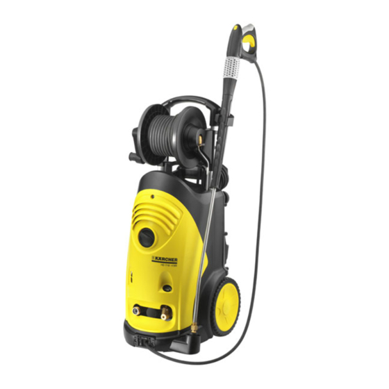
- Page 1 HD 6/16-4 M / MX HD 7/18-4 M / MX HD 9/19 M / MX HD 9/20-4 M / MX Service Manual English 5.906-246.0 Rev. 01 (09/14)
-
Page 2: Table Of Contents
Contents Preface Safety instructions Hazard levels Technical Features Drive Pump Detergent system Electrical system Other features Field of application Type plate Parts of the system Front view 5.1.1 M-device 5.1.2 MX-device Rear view Bottom view 5.3.1 Pump head HD 6/16, HD 9/20 5.3.2 Pump head HD 7/18, HD 9/19 Front view (without cover) Front view (electric box opened) -
Page 3: Preface
Preface Good service work requires extensive and practice-orient- ed training as well as well-structured training materials. Hence we offer regular basic and advanced training pro- grammes covering the entire product range for all service engineers. In addition to this, we also prepare service manuals for im- portant appliances - these can be initially used as instruc- tion guides and later on as reference guides. -
Page 4: Technical Features
Technical Features These devices are the new top models among the mobile high-pressure cleaners of the mid-range. Their compact and vertical design allows easy handling and space-saving storage. Drive 4-pin, electro mo- Cooling Voltage/cur- rent type HD 6/16-4 M/MX Air-cooled 1400 230 V / 1~ / 50 Hz... -
Page 5: Other Features
Other features Softgrip-Easypress gun with improved ergonomics – Highest operating comfort thanks to improved, continu- – ous pressure and water volume regulation Servopress rotary regulator with ceramic insert – Improved mobility on stairs thanks to large full rubber – wheels (Ø 250mm) Easy oil level check from the outside, without removal –... -
Page 6: Parts Of The System
Parts of the system Front view 5.1.1 M-device 1 Lock trigger gun 2 Lever for trigger gun 3 Trigger gun 4 Power press regulator Pressure/ quantity regulation 5 High pressure hose 6 Spray lance 7 Mains cable with mains plug 3-phase appliances 8 Mains cable with mains plug 1-phase appliances... -
Page 7: Rear View
Rear view 1 Hose drum 7 Bottle holder for detergent 2 Crank, hose drum 8 Connection 1 3 High pressure hose Detergent 4 Detergent 9 Dosage valve for detergent 5 Storage mains connection, compartment for replace- Switch-over from detergent bottle 1 to 2 ment nozzle 10 Storage, trigger gun with spray lance 6 Connection 2... -
Page 8: Bottom View
Bottom view 5.3.1 Pump head HD 6/16, HD 9/20 1 High pressure connection 2 Overflow valve 3 Pump head 4 Control piston, pressure switch 5 Pressure switch Q2/B1 6 Water connection Note The pressure switch is not adjustable. 5.3.2 Pump head HD 7/18, HD 9/19 1 High pressure connection 2 Overflow valve 3 Pump head... -
Page 9: Front View (Without Cover)
Front view (without cover) 1 Electronics system 2 Detergent hose 3 Pump motor 4 Manometer 5 Detergent hose with check valve 6 Detergent injector 7 High pressure connection 8 High pressure line 9 Safety clip, high pressure line. 10 Overflow valve 11 Pump head 12 Connection for water supply with filter 13 Oil tank... -
Page 10: 3-Phase Device
HD 6/16-4 Version 2 Power switch Capacitors 5.5.2 3-phase device HD 7/18-4 HD 9/19 Power switch Pressure switch connection HD 9/20-4 Power switch Contactor English 5.906-246.0 Rev. 01 (09/14) -
Page 11: Function
Function Motor/pump unit 1 Screw fan wheel attachment 15 Oil seal 2 Fan wheel 16 Low pressure seal 3 Motor bearing, rear (B bearing) 17 High pressure seal 4 Motor casing 18 Suction side pump 5 Motor shaft 19 Suction valve 6 Stator 20 Control piston, pressure switch 7 Rotor... -
Page 12: Pump Head
Pump head 1 Overflow valve 2 Detergent injector 3 Control pressure injector 4 Pressure holding valve 5 Pressure valves 6 Suction valves 7 Pump head 6.2.1 Versions A Pump head old B Pump head new 1 Pressure holding valve English 5.906-246.0 Rev. 01 (09/14) -
Page 13: High Pressure Seal / Low Pressure Seal
6.2.2 High pressure seal / low pressure seal Note Pay attention to installation position of the seals. 1 Bushing 2 O ring 3 Disc 4 High pressure seal 5 Low pressure seal 6 Disc 1 High pressure seal 2 Disc 3 O ring 4 Bushing 5 Disc... -
Page 14: Pump Diagram
Pump diagram 6.3.1 HD 6/16-4, HD 9/20-4 Trigger gun and servopress rotary regulator opened: holding valve via the control pressure injector to the high pressure outlet. 1 Manometer The ball of the overflow valve is pressed onto the valve 2 Pressure holding valve seat by the pump pressure and thus seals the connecting 3 Pressure room with pressure valves boring to the suction chamber. - Page 15 With the power press regulator partially closed, the pres- 1 Manometer sure in the pressure room will not rise any further. Howev- 2 Pressure holding valve er, due to less water volume, the effect of the control 3 Pressure room with pressure valves pressure injector decreases, so that the pressure in the 4 Pressure switch Q2/B1...
- Page 16 Trigger gun closed: Upon closing the trigger gun, the pressure in the pressure 1 Manometer room rises abruptly. This pressure peak will affect the pis- 2 Pressure holding valve ton rod and the pressure switch via the connecting boring. 3 Pressure room with pressure valves The ball is pressed out of its seat by the piston road and 4 Pressure switch Q2/B1...
-
Page 17: Hd 7/18-4, Hd 9/19
6.3.2 HD 7/18-4, HD 9/19 Trigger gun and servopress rotary regulator opened: When the power press regulator is opened all the way, the 1 Manometer water flows from the pressure room through the pressure 2 Pressure holding valve holding valve via the control pressure injector to the high 3 Pressure room with pressure valves pressure outlet. - Page 18 Servopress rotary regulator partially closed: With the power press regulator partially closed, the pres- 1 Manometer sure in the pressure room will not rise any further. Howev- 2 Pressure holding valve er, due to less water volume, the effect of the control 3 Pressure room with pressure valves pressure injector decreases, so that the pressure in the 4 Pressure switch...
- Page 19 Upon closing the trigger gun, the pressure in the pressure 1 Manometer room rises abruptly. This pressure peak will affect the pis- 2 Pressure holding valve ton rod and the pressure switch via the connecting boring. 3 Pressure room with pressure valves The ball is pressed out of its seat by the piston road and 4 Pressure switch the entire flow volume can flow to the suction room via the...
-
Page 20: Hand Spraygun
Hand spraygun 1 Lock trigger gun 2 Casing shell 3 Hand lever 4 High pressure hose 5 Hose guide 6 Safety clip 7 Needle bearing 8 Coupling high-pressure hose/trigger gun 9 O ring 10 Node piece Function When the manual lever is actuated, the valve in the node piece opens and the water can flow from the hose through the gun into the spray lance. -
Page 21: Pressure And Volume Regulation
Pressure and volume regulation 1 Connection trigger gun 2 Connecting pin 3 Ceramic disc on gun side 4 Ceramic disc on spray pipe side 5 Casing of rotating regulator 6 Handle of rotary regulator 7 Spray lance connection The pressure and volume regulation is designed as a rota- ry regulator between the trigger gun and the spray lance. -
Page 22: Triple Nozzle
Triple nozzle A High-pressure round jet B Flat low pressure spray (CHEM) for operating using de- tergents or cleaning at low pressure. C High pressure flat spray (25°) for large dirt areas The triple nozzle can be adjusted to three different set- tings. -
Page 23: Basic Settings And Service Procedures
Basic settings and service procedures Adjusting the overflow valve 1 Spring 2 Setting nut, self-locking 3 Overflow valve spindle with hexagon 7.1.1 Trigger gun with servopress pressure regulator Connect the test manometer with high-pressure hose and the trigger gun with servopress rotary regulator to the high pressure outlet. -
Page 24: Troubleshooting
Troubleshooting Findings Possible cause Correction Appliance is not running Power supply interrupted Check connection cable for damages. Check the supply voltage. Engine is overheated Turn device switch on "0" and let engine cool off for min. 5 minutes. Power switch Check/replace the appliance switch. -
Page 25: Technical Documentation
Technical Documentation Appliance type Piston diame- Appliance no. Circuit diagram Operating instructions Spare parts list ter in mm HD 6/16-4 M 1.524.120.0 0.089-003.0 5.964-870.0 5.971-970.0 HD 6/16-4 MX 1.524.125.0 0.089-003.0 5.964-870.0 5.972-055.0 HD 7/18-4 M 1.524.220.0 0.087-804.0 5.964-870.0 5.972-050.0 HD 7/18-4 MX 1.524.225.0 0.087-804.0 5.964-870.0... - Page 26 Sound pressure level L dB(A) Uncertainty K dB(A) Sound power level L + Uncertainty K dB(A) Fuel Amount of oil 0,75 Oil grade SAE 15W40 SAE 90 Hypoid Dimensions and weights Length Width Height 1000 Weight without accessories (MX) 48 (50) 49 (52) 47 (55) 48 (50)
-
Page 27: Special Tools
Special tools Electric measuring appliance 6.803-022.0 Shut-off valve with thermometer 4.580-034.0 Removal pliers, pressure/suction valves 4.901-062.0 Installation mandrel oil seal, high-pressure 5.901-106.0 and water sieves seal Piston diameter 16 mm HD 6/16-4 HD 9/19 Installation sleeve, high pressure seal 5.901-105.0 Piston diameter 16 mm HD 6/16-4 HD 9/19... - Page 28 Adapter system 2000, M22x1.5 with ex- 4.401-072.0 For hose drum appliances: Adapter M22 (in- 4.424-004.0 tended union nut side) onto 11 mm male coupling Test manometer for working pressure 4.742-025.0 Installation and removal tools, overflow valve 4.901-054.0 seat English 5.906-246.0 Rev. 01 (09/14)
-
Page 29: Circuit Diagram
Circuit diagram When working on the device, please always use the cur- rent circuit diagram in DISIS. 0.089-003.0 HD 6/16 C1 Capacitor C2 Capacitor M1 Motor Q1 Power switch Q2 Pressure switch English 5.906-246.0 Rev. 01 (09/14) - Page 30 0.087-804.0 HD 7/18, HD 9/19 M1 Motor Q1 Power switch Q2 Pressure switch U1 Red Black V1 Yellow W1 Black White U2 White Yellow V2 Blue Blue W2 Grey Brown English 5.906-246.0 Rev. 01 (09/14)
- Page 31 0.088-885.0 HD 9/20 Pressure switch Contactor Motor Power switch WSK Winding protection in the motor U1 Red V1 Yellow W1 Black U2 White V2 Blue W2 Grey English 5.906-246.0 Rev. 01 (09/14)
-
Page 32: Torques
Torques Name Cylinder head screws 40 - 45 Piston casing 5 - 7 Trigger gun, pressure regulator Screw connection pressure valves 40 - 45 Screw connection pressure switch 15 - 17 Screw connection suction valves 35 - 40 Overflow valve seat 8 - 10 Swash plate 9 - 12...