Table of Contents
Advertisement
Quick Links
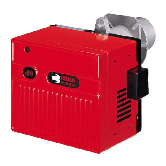
Installation & Operating Manual
Single stage operation oil burners
NON-RETROFIT APPLICATIONS
If this burner is being installed in a packaged unit (ie. burner comes with a boiler or furnace), follow
the installation and set-up instructions supplied with the heating unit, as settings may differ from
those shown in this manual.
- The following pages contain information, descriptions and diagrams for the proper installation
and wiring of the burner. Please read carefully before attempting final installation.
- This manual is to remain with the final installation designation. It is the installer's responsibility to en-
sure that the burner installation and operation instructions mentioned in this manual are followed and
operated within local code authority limits.
CODE
3726312
3726392
MODEL
F10
WITH HYDRAULIC JACK
F10
WITH HYDRAULIC JACK
TYPE
263T
263T
2902451 (1) - 07/2008
Advertisement
Table of Contents

Related Manuals for Riello 40 F10 A


Summary of Contents for Riello 40 F10 A
- Page 1 Installation & Operating Manual Single stage operation oil burners NON-RETROFIT APPLICATIONS If this burner is being installed in a packaged unit (ie. burner comes with a boiler or furnace), follow the installation and set-up instructions supplied with the heating unit, as settings may differ from those shown in this manual.
- Page 2 INSTALLLATION PRECAUTIONS AIR FOR COMBUSTION Do not install burner in room with insufficient air for combustion. Be sure there is an adequate air supply for combustion if the boiler/furnace room is enclosed. It may be necessary to create a window to permit suffi- cient air to enter the boiler/furnace room.
-
Page 3: Table Of Contents
TABLE OF CONTENTS PACKAGE CONTENTS LIST ..............1 SERIAL NUMBER IDENTIFICATION. -
Page 4: Package Contents List
PACKAGE CONTENTS LIST Your Riello 40 burner should include the following parts. Please check to make sure all parts are present before begin- ning the installation. Quantity Description Code Burner chassis with cover 3726312 - 3726392 Universal mounting flange + mounting gasket... -
Page 5: Technical Data
230 Watts Motor (rated) 3250 rpm Run Current 2.2 AMP Capacitor 12.5 Microfarads 260V Pump pressure 100 to 200 psi RIELLO 530 SE/C 24V (for code 3726312) Primary control RIELLO 530 SE/C (for code 3726392) Ignition transformer 8kV 16mA D7428... -
Page 6: Initial Set-Up
INITIAL SET-UP A) Remove burner and air tube from cartons. Check parts list (inside cover) to ensure all parts are present. B) Remove burner cover by loosing the three screws securing it. Remove control box and air tube cover. C) Remove drawer assembly from air tube, insert nozzle and set Turbulator adjustment for specific input required, then set aside. -
Page 7: Method 2-Semi-Flange Collar
A) Insert the two BOLTS (1) into the UNIVERSAL MOUNTING FLANGE (10) from the flat side, ensuring the bolt heads are flush with the flat surface. Secure in place using two special CHROME NUTS (2) provided. B) Position the MOUNTING GASKET (3) between the flat surface of the UNIVERSAL MOUNTING FLANGE (10) and the appliance. -
Page 8: Electrical Connections
ELECTRICAL CONNECTIONS It is advisable to leave the control box off the sub-base while completing the electrical connection to the burner. 1) Wire access hole (Use BX electrical connector) 2) Earth ground conductor terminal (Green wire) 3) Hot conductor terminal (Black wire) 4) Neutral conductor terminal (White wire) 5) Strain relief clamp WARNING:... -
Page 9: Nozzle Placement
APPLICATION FIELD WIRING (only for code 3726392 - primary control 530SE/C) 120V 120V DIRECT LINE LOW VOLTAGE VOLTAGE FUSE 15A FUSE 15A LINE SAFETY LINE SAFETY SWITCH SWITCH OPERATING OPERATING LIMIT SWITCH LIMIT SWITCH SAFETY SAFETY LIMIT SWITCH LIMIT SWITCH SWITCHING RELAY FACTORY WIRED... -
Page 10: Insertion / Removal Of Drawer Assembly
INSTALLATION/REMOVAL OF DRAWER ASSEMBLY A) To remove drawer assembly, loosen SCREW (3), then unplug CONTROL BOX (1) by carefully pulling it back and then up. B) Remove the AIR TUBE COVER PLATE (5) by loosening the two retaining SCREWS (4). C) Loosen SCREW (2), then slide the complete drawer assembly out of the combustion head as shown. -
Page 11: Oil Line Connections
All pump port threads are British Parallel thread design. Direct connection of NPT threads to the pump will damage the pump body. Riello manometers and vacuum gauges do not require any adapters, and can be safely connected directly to pump ports. An NPT (metric) adapter must be used when connecting other gauge models. -
Page 12: Two Line (Lift System)
TWO LINE (LIFT SYSTEM) A) The burner is shipped with the pump set to oper- 2 LINE (LIFT) SYSTEM - PIPE LENGTHS ate on a two line system. Suction and return lines 3/8” OD 1/2” OD (7 & 11 in drawing on page 7) should be the same Feet Meters Feet... -
Page 13: Setting The Air Adjustment Plate
SETTING THE AIR ADJUSTMENT PLATE A) The hydraulic AIR SHUTTER (1) is operated by the HYDRAULIC JACK (6), assuring complete opening of the combustion air intake. Regulation of the combustion air flow is made by adjustment of the manual AIR ADJUSTMENT PLATE (4) after loosening the FIXING SCREWS (3 &... -
Page 14: Ducted Combustion Air Intake Applications
DUCTED COMBUSTION AIR INTAKE APPLICATIONS The “Ducted combustion air intake kit” (see P.N. 3002762 in the spare parts list - OPTIONS), allows ducting of external air directly into the burner. A 4” diameter air intake is provided in the kit. To mount this kit on the burner, please follow the installation description given in the kit instruction sheet. -
Page 15: Burner Start-Up Cycle
G) On the outside of the wall, use an approved intake air hood, located above the snow line and in such way as to prevent leaves and/or other debris from blocking the air flow. Refer to local codes for proper location of inlet. COMBUSTION CHAMBER Follow the instructions furnished by the boiler/furnace manufacturer. -
Page 16: Exploded Spare Parts List
EXPLODED SPARE PARTS LIST 2451... -
Page 17: Spare Parts List
SPARE PARTS LIST CODE DESCRIPTION CODE DESCRIPTION • • 3006911 OPTIONAL HYDRAULIC JACK • • • • 3006912 3002762 CAPILLARY TUBE DUCTED COMBUSTION AIR INTAKE KIT • • 3000879 HYDRAULIC AIR SHUTTER • • 3005788 • • • • 3005844 3949071 SHORT COMBUSTION HEAD 5”... -
Page 18: Burner Start-Up Form
35 Pond Park Rd. 2165 Meadowpine Blvd. Hingham, MA 02043 Mississauga,On L5H 3R2 Phone: 781-749-8292 Phone: 905-542-0303 Toll Free: 800-992-7637 Toll Free: 800-387-3898 Fax: 781-740-2069 Fax: 905-542-1525 BURNER START- UP FORM * Burner S/N. or Model: Appliance: Installer name: Company: Installation date: Address: Phone:... - Page 20 35 Pond Park Road 2165 Meadowpine Blvd Hingham, MA 02043 Mississauga, ON L5N 6H6 Phone 781-749-8292 Phone 905-542-0303 Toll Free 800-992-7637 Toll Free 800-387-3898 Fax 781-740-2069 Fax 905-542-1525 www.riellousa.com www.riellocanada.com Technical Support Hotline 1-800-4-RIELLO 1-800-474-3556...