Daikin BRC1E62 Installation Manual
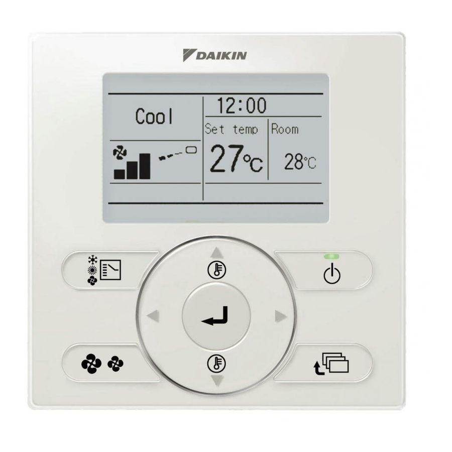
Wired remote
controller
Hide thumbs
Also See for BRC1E62:
- Operation manual (64 pages) ,
- Operation manual (64 pages) ,
- Operation manual (64 pages)

Related Manuals for Daikin BRC1E62


Summary of Contents for Daikin BRC1E62
-
Page 1: Wired Remote Controller
WIRED REMOTE CONTROLLER INSTALLATION MANUAL BRC1E62 Be sure to read this installation manual before installing this product. -
Page 2: Table Of Contents
Contents 1. Safety Precautions ..........2 2. Accessories ............4 3. Remote controller installation procedure ..4 4. Functions and menu items of remote controller buttons ....... 10 5. Power-on ............12 6. Field settings ........... 13 7. Test operation method (in the case of SPLIT system) .......... -
Page 3: Safety Precautions
1. Safety Precautions „ Also refer to installation manual attached to the indoor unit. Please read these "Safety Precautions" carefully before installing the remote controller. ● This manual classifies the precautions into WARNINGS and CAUTIONS. Be sure to follow all the precautions below: They are all important for ensuring safety. Indicates a potentially hazardous situation which, if not avoided, could WARNING result in death or serious injury. - Page 4 CAUTION To avoid electric shocks due to entry of water or insects, fill the wiring through hole with putty. Do not operate with wet hands to avoid electric shocks. Do not wash the remote controller with water. It may result in electric shocks or a fire. Install the air conditioner, power supply wiring, remote controller wiring and transmission wiring at least 1 meter away from televisions or radios to prevent image interference or noise.
-
Page 5: Accessories
2. Accessories The following accessories are included. Operation Installation Wood screw Small screw Clamp Wiring retainer manual manual (M3.5×16) (M4×16) (2 pcs.) (2 pcs.) (1 pc.) (1 pc.) (1 pc.) (1 pc.) 3. Remote controller installation procedure 3-1 Determine where to install the remote controller. Make sure to follow "... - Page 6 3-4 Determine the direction of controller wiring outlet (back outlet, left outlet, top left outlet, top center outlet). 3-4-1 Back outlet 3-4-2 Left outlet Cut off resin area (hatched area). Cut off thin area (hatched area) with nippers or the like, and then remove burr with a file or the like.
- Page 7 Prepare the wiring for connection to the remote controller following these instructions. Approx.10 mm For easy wiring, it is better to keep approx.10 mm difference Peel the insulator and sheath between the length of 2 wires. Cutting guideline of the wiring Sheath stripping length: ●...
- Page 8 3-5-2 Left outlet Indoor unit P1P2 Lower case Upper case Printed Circuit Board 3-5-3 Top left outlet Wiring retainer Wiring retainer Upper case As shown to the left, Wiring install wiring retainer in order to prevent wiring pinching. Cross-section Indoor unit P1P2 Lower case Upper case...
- Page 9 CAUTION ● Perform the wiring apart from a power line not to receive electrical noise (external noise). ● Seal the wiring outlet hole securely with putty (field supply) to prevent entry of insects or the like. 3-6 Fixing procedure of lower case. In case of wiring a remote controller through top center outlet or back outlet, perform wiring through the outlet hole in the lower case before it is wall install.
- Page 10 Switch box for 1 unit (with no cover) Switch box (field supply) (Use optional accessory KJB111A) (Installation pitch) Small screws (M4×16) CAUTION ● Select flat place for installation face as possible. ● And, do not tighten the installation screws too much not to deform the lower case. 3-7 Install the upper case as original condition.
-
Page 11: Functions And Menu Items Of Remote Controller Buttons
4. Functions and menu items of remote controller buttons 4-1 Functions and menu items (1) Mode Selector button (11) LCD (with backlight) (4) Up button (5) Down button (6) Right button (7) Left button (9) Operation lamp (Green) (8) ON/OFF button (3) Menu/Enter button (10) Cancel button (2) Airflow Setting button... - Page 12 (7) Left button " " Service Settings menu ● Used to highlight the next items on the left-hand side. Test Operation ● Display contents are changed to Maintenance Contact previous screen per page. Field Settings Min Setpoints Differential (8) ON/OFF button Group Address ●...
-
Page 13: Power-On
5. Power-on ● Check for completion of indoor/outdoor units wiring. ● Check for closing of control box lid of indoor and outdoor units before turn on the power. Followings is displayed after turn <Main remote controller> <Sub remote controller> on the power. "Checking the connection. -
Page 14: Field Settings
6. Field settings Press and hold the Cancel button <Basic screen> for 4 seconds or longer. Service Settings menu is displayed. Select in the Field settings Service Settings menu, and press Menu/Enter button. Field settings screen is displayed. Press and hold Cancel button for 4 seconds or Highlight the Mode No., and longer during backlight lit. - Page 15 Press Menu/Enter button. Setting confirmation screen is displayed. <Setting confirmation screen> Select and press Menu/ Field settings Enter button. Setting details are Save the settings? saved and Field settings screen returns. In the case of multiple setting Return Setting changes, repeat " "...
- Page 16 Mode SECOND CODE NO. Note) 2 FIRST Description of setting CODE Note) 1 ON/OFF input from outside (Setting ON/OFF for when forced ON/OFF is to be Forced OFF — — operation operated from outside). 12 (22) Thermostat differential changeover (Setting for when using remote 0.5°C 1°C —...
-
Page 17: Test Operation Method (In The Case Of Split System)
7. Test operation method (in the case of SPLIT system) * In the case of VRV system, refer to the manual attached to the outdoor unit. Also refer to installation manuals attached to the indoor unit and the outdoor unit. ●... - Page 18 Press ON/OFF button within about 10 seconds. The test operation starts. Cool Check operation condition for 3 minutes. Press ON/OFF button * Note) In the case of above-men- (within 10 seconds). Test Operation tioned procedures in reverse order, test operation can start as well. Air volume/direction Air Volume Direction...
- Page 19 CAUTION ● If operation is not available due to any malfunction, refer to following Malfunction diagnosis method . ● After the test operation finishes, check that malfunction (error) code history is not displayed in the Maintenance Information screen of the Main menu according to the following procedure. Press Menu/Enter button in the Basic 7-14 <Basic screen>...
-
Page 20: Checking Procedure Of Malfunction (Error) History
Remote controller display Description ● Power outage, power voltage failure or open-phase ● Wrong wiring (between indoor and outdoor units) ● Indoor Printed Circuit Board assembly failure No display ● Remote controller wiring disconnection ● Remote controller failure ● Fuse blown (outdoor unit) Display of "Checking the connection. -
Page 21: Registration Method Of The Maintenance Contact
9. Registration method of the Maintenance Contact ● Registration of the service contact. Press and hold Cancel button for <Basic screen> 4 seconds or longer in the Basic screen. Service Settings menu is displayed. <Service Settings menu screen> Select in the Service Settings Maintenance Contact Test Operation... -
Page 22: Confirmation Of Registered Details
10. Confirmation of registered details Press Menu/Enter button in the Basic 10-1 <Basic screen> screen. 10-1 Main menu is displayed. Select Cool Maintenance Information Set to the Main menu, and press Menu/Enter Cool °C button. Press Menu/Enter button. Press Cancel button twice. 10-2 The Basic screen returns. -
Page 23: Clock & Calendar
11. Clock & Calendar Press Menu/Enter button in the Basic 11-1 <Basic screen> screen. Main menu is displayed. Select in the Main Clock & Calendar <Main menu screen> menu, press Menu/Enter button. 11-1 Main Menu Maintenance Information Press " " buttons to select 11-2 Configuration Current Settings... -
Page 24: Language
12. Language Press Menu/Enter button in the Basic 12-1 <Basic screen> screen. Main menu is displayed. Select in the Main menu, Language <Main menu screen> press Menu/Enter button. 12-1 Main Menu Maintenance Information Press " " (Down/Up) buttons to 12-2 Configuration Current Settings select "Language"... -
Page 25: Prohibit Buttons
13. Prohibit buttons ● Restriction of the number of operable <Basic screen> buttons. Press Menu/Enter button in the Basic <Main menu screen> 13-1 screen. 13-1 Main Menu Main menu is displayed. Air Flow Direction Quick Start Normally, "Lock function" is not shown Ventilation Energy Saving Options in Main menu. -
Page 26: Prohibit Function
14. Prohibit Function ● Restriction of the number of operable functions. Press Menu/Enter button in the Basic 14-1 <Basic screen> screen. Main menu is displayed. <Main menu screen> As usual, "Lock function" is not shown 14-1 in Main menu. Main Menu Press Menu/Enter button for 4 seconds Air Flow Direction Quick Start... - Page 28 3P243521-4E EM12A040 (1303) AK...