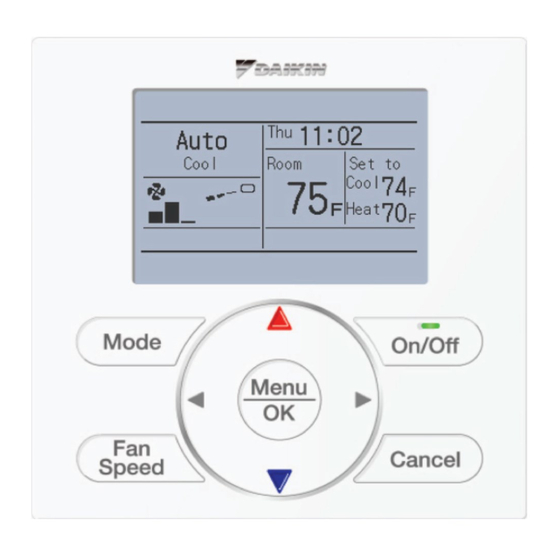
Daikin BRC1E73 Installation And Operation Manual
Navigation remote controller
wired remote controller
Hide thumbs
Also See for BRC1E73:
- Installation manual (68 pages) ,
- Operation manual (160 pages) ,
- Service manual (92 pages)
Table of Contents
Advertisement
Advertisement
Table of Contents

Related Manuals for Daikin BRC1E73


Summary of Contents for Daikin BRC1E73
- Page 1 EDUS721438 Navigation Remote Controller (Wired Remote Controller) BRC1E73...
-
Page 3: Table Of Contents
EDUS721438 Contents 1. Specifications ....................2 2. Dimensions ....................3 3. Restrictions ....................4 4. Operation Manual..................5 4.1 Safety Considerations .................. 6 4.2 Button Locations and Descriptions............... 8 4.3 Names and Functions ................10 4.4 Basic Operation..................14 4.5 Quick Reference..................24 4.6 Menu Options ..................... 26 4.7 Maintenance.................... -
Page 4: Specifications
Specifications EDUS721438 1. Specifications New Remote Controller BRC1E73 Dimension (H × W × D) 4’3/4” × 4’3/4” × 3/4” Display size (H × W) 1’25/32” × 2’13/16” Display method Full dot method (dot 160 × 255) Backlight (Background color: white) -
Page 5: Dimensions
EDUS721438 Dimensions 2. Dimensions BRC1E73... -
Page 6: Restrictions
Restrictions EDUS721438 3. Restrictions 1. In the case of 2 remote control system. Main Wireless BRC1E73 BRC1E72 BRC4*** BRC7*** BRC1E73 – – BRC1E72 – – Wireless BRC4*** – – – BRC7*** : Connectable – : Not connectable Due to the limited power supply capacity, there are some restrictions when controlling 2 remote controllers. -
Page 7: Operation Manual
Daylight Saving Time ..........45 Language ............... 48 Maintenance Reset Filter Indicator ..........48 Maintaining the Unit and LCD Display ....49 Reference Information Error Code Display ..........50 After-sale Service ........... 51 English 3P243520-7N 01_EN_3P243520-7N.indd 1 11/27/2014 10:34:34 AM BRC1E73... -
Page 8: Safety Considerations
WARNING Do not modify or repair the remote controller. Consult your Daikin dealer for any modifi cation or for repairs. Do not relocate or reinstall the remote controller by yourself. Improper installation may result in electric shocks or fi re. - Page 9 Never disassemble the remote controller. Touching the interior parts may result in electric shocks or fi re. Consult your Daikin dealer for internal inspections and adjustments. Do not touch the remote controller buttons with wet fi ngers. Touching the buttons with wet fi ngers can cause an electric shock.
-
Page 10: Button Locations And Descriptions
Do not pull or twist the remote controller cord, the remote controller may be damaged. Do not use objects with sharp ends to press the buttons on the remote controller, damage may result. English 3P243520-7N 01_EN_3P243520-7N.indd 4 11/27/2014 10:34:35 AM BRC1E73... - Page 11 Used to change the selected item. Right button Used to highlight the next items on the right-hand side. Each screen is scrolled in the right-hand direction. English 3P243520-7N 01_EN_3P243520-7N.indd 5 11/27/2014 10:34:35 AM BRC1E73...
-
Page 12: Names And Functions
15. ( ) Unable to Cool schedule No Selectable No Airflow Display Item AUTO STANDBY Direction display PURIFY (with no selectable (with no airflow direction display item selected) settings) <Detailed display example 2> English 3P243520-7N 01_EN_3P243520-7N.indd 6 11/27/2014 10:34:35 AM BRC1E73... - Page 13 Note for all display modes Depending on the fi eld settings, while the indoor unit is stopped, OFF may be displayed instead of the operation mode and/or the setpoint may not be displayed. English 3P243520-7N 01_EN_3P243520-7N.indd 7 11/27/2014 10:34:35 AM BRC1E73...
- Page 14 In a remote control group, the message will not appear if at least one of the indoor units provides the corresponding function. English 3P243520-7N 01_EN_3P243520-7N.indd 8 11/27/2014 10:34:35 AM BRC1E73...
- Page 15 Room temperature is selected by default. For other choices see page 41. Unable to schedule Displayed when the clock needs to be set. The schedule function will not work unless the clock is set. English 3P243520-7N 01_EN_3P243520-7N.indd 9 11/27/2014 10:34:36 AM BRC1E73...
-
Page 16: Basic Operation
Note MASTER Both heat and cool mode may not be selected if the unit is CONTROLLED Cool master controlled. See page 16 if MASTER CONTROLLED icon Set to fl ashes. Return Setting English 3P243520-7N 01_EN_3P243520-7N.indd 10 11/27/2014 10:34:36 AM BRC1E73... - Page 17 If the Auto is selected for the fan speed, the fan speed varies Medium Auto automatically based on the difference between setpoint and room temperature. High Med High fi ve fan speeds English C: 3P243520-7N 01_EN_3P243520-7N.indd 11 11/27/2014 10:34:37 AM BRC1E73...
- Page 18 When the system starts heating operation, the indoor unit fan will operate with a delay in order to prevent a cold draft. (In that case, “ STANDBY ” will be displayed on the remote controller.) English 3P243520-7N 01_EN_3P243520-7N.indd 12 11/27/2014 10:34:37 AM BRC1E73...
- Page 19 Dry mode. Adjust Airfl ow Direction from the main menu (see page 23) If the connected indoor unit does not have oscillating louvers, this function will not be available. English 3P243520-7N 01_EN_3P243520-7N.indd 13 11/27/2014 10:34:37 AM BRC1E73...
- Page 20 When enabled, the Setback mode becomes active when the indoor unit is turned off by either the user, a schedule event or an off timer. This function is not available by default. It can be enabled by the system installer. English 3P243520-7N 01_EN_3P243520-7N.indd 14 11/27/2014 10:34:38 AM BRC1E73...
- Page 21 Changes to the ventilation mode are made from the main menu. Ventilation Mode: Auto, ERV, and Bypass Changes to the ventilation rate are made from the main menu. Ventilation Rate: Low or High English 3P243520-7N 01_EN_3P243520-7N.indd 15 11/27/2014 10:34:38 AM BRC1E73...
- Page 22 If the outdoor unit is confi gured as cool/heat changeover master, all remote controllers serving the associated indoor units will display its “ ” icon. MASTER CONTROLLED Set the cool/heat changeover master indoor unit as outlined below. English 3P243520-7N 01_EN_3P243520-7N.indd 16 11/27/2014 10:34:38 AM BRC1E73...
- Page 23 Simultaneously, the other indoor units on the system will follow suit and change modes to refl ect the new mode selected at the changeover master remote controller. English 3P243520-7N 01_EN_3P243520-7N.indd 17 11/27/2014 10:34:39 AM BRC1E73...
- Page 24 Branch Selector unit. Set any one of the indoor units as the Set any one of the indoor units as the cool/heat changeover master. cool/heat changeover master. English 3P243520-7N 01_EN_3P243520-7N.indd 18 11/27/2014 10:34:39 AM BRC1E73...
- Page 25 All buttons are disabled when the keys Set to are locked. To cancel the key lock mode, continue Return Setting pressing Menu/OK button for at least four seconds while the backlight is illuminated. English 3P243520-7N 01_EN_3P243520-7N.indd 19 11/27/2014 10:34:42 AM BRC1E73...
-
Page 26: Quick Reference
Possible to set in 10 minute increments from 30 to 180 minutes. Used to select whether temperature values Celsius / Fahrenheit – will be displayed in Celsius or Fahrenheit. English 3P243520-7N 01_EN_3P243520-7N.indd 20 11/27/2014 10:34:42 AM BRC1E73... - Page 27 In this case, the following items should be confi gured in the main remote controller. Individual Airfl ow Direction Setback Schedule Draft Prevention Outdoor unit Two remote Off timer controllers in control English 3P243520-7N 01_EN_3P243520-7N.indd 21 11/27/2014 10:34:42 AM BRC1E73...
-
Page 28: Menu Options
To go back to the basic screen from the main menu, press Cancel button. Note If a button is not pressed for 5 minutes during confi guration, the controller will automatically revert to the basic screen. English 3P243520-7N 01_EN_3P243520-7N.indd 22 11/27/2014 10:34:42 AM BRC1E73... - Page 29 4 : Position 4 Airfl ow direction setting (left/right) Notice These operation and screen are example of single airfl ow direction type indoor unit. It is different from Single fl ow cassette model. English 3P243520-7N 01_EN_3P243520-7N.indd 23 11/27/2014 10:34:42 AM BRC1E73...
- Page 30 Airflow Direction Louver1 Louver2 Swing Swing Setting If dual airfl ow directions are set, then the Cool dual airfl ow direction icons are displayed in the basic screen. Basic screen (Detailed display) English 3P243520-7N 01_EN_3P243520-7N.indd 24 11/27/2014 10:34:44 AM BRC1E73...
-
Page 31: Louver Setting
15) can be selected. Setting Note In case of four outlets (cassette type), you can control each one of the four louvers individually (the following marks are beside each air outlet: , English 3P243520-7N 01_EN_3P243520-7N.indd 25 11/27/2014 10:34:44 AM BRC1E73... - Page 32 Louver Setting List Unit 0 Press buttons to go to the next unit. Outletmark Direction Indiv. Position 0 Press Cancel button to return to the Position 0 Position 0 previous menu. Position 0 English 3P243520-7N 01_EN_3P243520-7N.indd 26 11/27/2014 10:34:46 AM BRC1E73...
- Page 33 (Automatic swing) Movement of airfl ow direction louver Under the operating conditions shown next, airfl ow direction is controlled automatically. Actual operation may be different than what is displayed on the remote controller. English 3P243520-7N 01_EN_3P243520-7N.indd 27 11/27/2014 10:34:46 AM BRC1E73...
- Page 34 Navigate to the ventilation screen Ventilation Ventilation Rate (see above) Ventilation Mode Press buttons to select Ventilation Rate on the ventilation Setting screen. Press Menu/OK button to display the ventilation rate screen. English 3P243520-7N 01_EN_3P243520-7N.indd 28 11/27/2014 10:34:47 AM BRC1E73...
- Page 35 Press Menu/OK button to display the ventilation mode screen. Pressing buttons cycles through the Ventilation Ventilation Mode settings in the order shown below. Auto Auto Bypass Setting Only modes that can be set are displayed. English 3P243520-7N 01_EN_3P243520-7N.indd 29 11/27/2014 10:34:47 AM BRC1E73...
-
Page 36: Auto Mode
Display the main menu screen. Main Menu Airflow Direction (See page 22.) Individual Airflow Direction Ventilation Press buttons to select Schedule Schedule Off Timer Celsius / Fahrenheit Press Menu/OK button to display the Setting schedule screen. English 3P243520-7N 01_EN_3P243520-7N.indd 30 11/27/2014 10:34:48 AM BRC1E73... - Page 37 Menu/OK button is pressed. Schedule Press buttons to Daily Patterns select 7 Days Weekday/Sat/Sun 7 Days Weekday/Weekend Everyday the daily patterns screen. Setting The confi rmation screen will appear when Menu/OK button is pressed. English 3P243520-7N 01_EN_3P243520-7N.indd 31 11/27/2014 10:34:48 AM BRC1E73...
- Page 38 – – :– – – – – – – – :– – – – – – – – :– – – – – – – – :– – – – – – Setting English 3P243520-7N 01_EN_3P243520-7N.indd 32 11/27/2014 10:34:48 AM BRC1E73...
- Page 39 – – :– – – – – – Setting Schedule Time Cool Heat – 6 :00 – 8 :00 – 5 :30 1 0 :00 – – :– – – – – – Setting English 3P243520-7N 01_EN_3P243520-7N.indd 33 11/27/2014 10:34:49 AM BRC1E73...
- Page 40 Schedule Save the settings? confi rmation screen. Pressing Menu/OK button confi rms the enable/disable setting for the schedule Setting and takes you back to the basic screen. English 3P243520-7N 01_EN_3P243520-7N.indd 34 11/27/2014 10:34:49 AM BRC1E73...
- Page 41 The confi rmation screen will appear. Press button to select on the Off Timer Save the settings? confi rmation screen. Pressing Menu/OK button confi rms the off timer and takes you back to the basic Setting screen. English 3P243520-7N 01_EN_3P243520-7N.indd 35 11/27/2014 10:34:50 AM BRC1E73...
- Page 42 Off Timer Save the settings? confi rmation screen. Pressing Menu/OK button confi rms the enable/disable for the off timer and Setting takes you back to the basic screen. English 3P243520-7N 01_EN_3P243520-7N.indd 36 11/27/2014 10:34:50 AM BRC1E73...
- Page 43 The error code history may also be displayed. If the Operation lamp is not fl ashing, the unit is working properly. The error code history is no longer displayed if you press On/Off button for more than 4 seconds. English 3P243520-7N 01_EN_3P243520-7N.indd 37 11/27/2014 10:34:50 AM BRC1E73...
- Page 44 The confi rmation screen will appear when Menu/OK button is pressed. Setting Press buttons to select Draft Prevention Save the settings? Press Menu/OK button to confi rm the settings and to return to the basic screen. Setting English 3P243520-7N 01_EN_3P243520-7N.indd 38 11/27/2014 10:34:51 AM BRC1E73...
- Page 45 On the contrast adjustment screen press Contrast Adjustment buttons until you reach the desired Dark contrast. Light After setting, press Menu/OK button and Setting return to the basic screen. English 3P243520-7N 01_EN_3P243520-7N.indd 39 11/27/2014 10:34:51 AM BRC1E73...
- Page 46 Press Menu/OK button to confi rm the Setting settings and return to the basic screen. Refer to Display Item to change the selectable display item for Detailed and Simple display modes. (See page 41.) English 3P243520-7N 01_EN_3P243520-7N.indd 40 11/27/2014 10:34:52 AM BRC1E73...
- Page 47 (for example, if it is in direct sunlight) and unit operation during defrosting. After setting, press Menu/OK button to confi rm settings and return to the basic screen. English 3P243520-7N 01_EN_3P243520-7N.indd 41 11/27/2014 10:34:52 AM BRC1E73...
- Page 48 Maintenance Information Configuration Clock & Calendar on the main menu Current Settings Clock & Calendar Daylight Saving Time screen. Setting Press Menu/OK button to display the clock & calendar screen. English 3P243520-7N 01_EN_3P243520-7N.indd 42 11/27/2014 10:34:52 AM BRC1E73...
- Page 49 Days of the week change automatically. Select Hour with buttons. Date & Time Year 2016 Change the hour with buttons. Month 10 Friday Holding down the button causes the 12:00 number to change continuously. Setting English 3P243520-7N 01_EN_3P243520-7N.indd 43 11/27/2014 10:34:53 AM BRC1E73...
- Page 50 Save the settings? confi rmation screen. Press Menu/OK button to confi rm the clock and return to the basic screen. Setting When setting the schedule, the display returns to the settings screen. English 3P243520-7N 01_EN_3P243520-7N.indd 44 11/27/2014 10:34:53 AM BRC1E73...
- Page 51 Maintenance Information Configuration select Daylight Saving Time on the Current Settings Clock & Calendar Daylight Saving Time main menu screen. Press Menu/OK Setting button to display the daylight saving time screen. English 3P243520-7N 01_EN_3P243520-7N.indd 45 11/27/2014 10:34:54 AM BRC1E73...
-
Page 52: Setting The Date
Display the daylight saving time screen. Daylight Saving Time Enable/Disable (See page 45.) DST Dates Press buttons to select DST Dates on the daylight saving time Setting screen. Press Menu/OK button to display the duration setting screen. English 3P243520-7N 01_EN_3P243520-7N.indd 46 11/27/2014 10:34:54 AM BRC1E73... - Page 53 When the time in the remote controller reaches 2:00 a.m. on the specifi ed start date, the clock is automatically set forward by one hour. When the time in the remote controller reaches 2:00 a.m. on the end date, the clock is automatically set back by one hour. English 3P243520-7N 01_EN_3P243520-7N.indd 47 11/27/2014 10:34:55 AM BRC1E73...
-
Page 54: Maintenance
Time to clean element This is not displayed when Simple display is set. Wash, clean, or replace the fi lter or element. For details, refer to the operation manual supplied with the indoor unit. English 3P243520-7N 01_EN_3P243520-7N.indd 48 11/27/2014 10:34:55 AM BRC1E73... - Page 55 If the dirt on the surface cannot be removed, soak the cloth in neutral detergent diluted with water, squeeze the cloth tightly, and clean the surface. Wipe the surface with a dry cloth. Note Do not use any paint thinner, organic solvent, or strong acid. English 3P243520-7N 01_EN_3P243520-7N.indd 49 11/27/2014 10:34:55 AM BRC1E73...
-
Page 56: Reference Information
Operation Manual EDUS721438 Reference Information Reference Information Error Code Display Contact your Daikin dealer in the following cases Operation If an error occurs, either one of the following items will fl ash in the basic screen. Cool Set to Error: Push Menu button The Operation lamp will fl... - Page 57 Do not relocate or reinstall the remote controller by yourself. Improper installation may result in electric shocks or fi re. Consult your Daikin dealer. Advise your Daikin Dealer of the following items Model name Date of installation Failure conditions: As precise as possible.
-
Page 58: Installation Manual
8. Procedure for Checking Error History ........18 9. Adding Maintenance Contact Information ........19 10. Confi rming Registered Details ..20 11. Clock & Calendar ......20 12. Language ......... 21 English 3P243521-7L 01_EN_3P243521-7L.indd 1 11/27/2014 11:21:41 AM BRC1E73... -
Page 59: Safety Considerations
WARNING Only qualifi ed personnel must carry out the installation work. Consult your Daikin dealer regarding relocation and reinstallation of the remote controller. Improper installation work may result in electric shocks or fi re. Electrical work must be performed in accordance with relevant local and national regulations and with instructions in this installation manual. - Page 60 A place where it is not exposed to direct sunlight. A place where it is far away from any heat source. A place where it is not affected directly by outside air. English 3P243521-7L 01_EN_3P243521-7L.indd 3 11/27/2014 11:21:42 AM BRC1E73...
-
Page 61: Accessories
Be careful not to damage the Screwdriver printed-circuit board with the screwdriver. Be careful not to let dust or moisture Lower case Insert and twist the screwdriver touch the printed-circuit board. lightly for removal. English 3P243521-7L 01_EN_3P243521-7L.indd 4 11/27/2014 11:21:42 AM BRC1E73... - Page 62 1. Switch box and control wiring are fi led supplied. Do not touch the remote controller printed-circuit board. Wiring Specifi cations Wiring Type Non-shielded, 2-conductor, stranded copper wire Wiring Size AWG-18 Wiring Length Maximum 1640 feet (500 m) English 3P243521-7L 01_EN_3P243521-7L.indd 5 11/27/2014 11:21:42 AM BRC1E73...
- Page 63 Back outlet Indoor unit Lower case Upper case Printed-circuit board Wire tie Wire tie Cross-section Secure the wire at the attachment point by using furnished wire Wire attachment tie. point <Wire attachment guideline> English 3P243521-7L 01_EN_3P243521-7L.indd 6 11/27/2014 11:21:42 AM BRC1E73...
- Page 64 Cross-section from being pinched during installation. Indoor unit P1P2 Lower case Upper case Printed- circuit board 3-5-4 Top center outlet Indoor unit P1P2 Wiring retainer Lower case Upper case Printed-circuit board English 3P243521-7L 01_EN_3P243521-7L.indd 7 11/27/2014 11:21:43 AM BRC1E73...
- Page 65 (46) Machine screws (field supply) or (use optional accessory KJB211A) NOTE Install the control on a fl at surface only. To prevent deformation of the lower case, avoid over-tightening the installation screws. English 3P243521-7L 01_EN_3P243521-7L.indd 8 11/27/2014 11:21:43 AM BRC1E73...
- Page 66 Align the upper case with tabs of the lower case (6 points), insert and install the upper case. Install the wiring with care to prevent pinching. Peel off the protective membrane which overlays the upper case. English 3P243521-7L 01_EN_3P243521-7L.indd 9 11/27/2014 11:21:43 AM BRC1E73...
-
Page 67: Functions And Menu Items Of Remote Controller Buttons
Used to highlight items to the right of the Maintenance Information currently selected item. Confi guration Display contents are changed to next Current Settings screen per page. Clock & Calendar Daylight Saving Time Language ∗Depending on connected model English 3P243521-7L 01_EN_3P243521-7L.indd 10 11/27/2014 11:21:44 AM BRC1E73... - Page 68 Highlighted display (selected items) Test Operation Maintenance Contact Field Settings Energy Saving Options In the highlighted display (selected items) Prohibit Function setting screen, button operation Min Setpoints Differential descriptions are displayed. Setting English 3P243521-7L 01_EN_3P243521-7L.indd 11 11/27/2014 11:21:44 AM BRC1E73...
-
Page 69: Power-On
If the basic screen is not displayed in 2 minutes after the “Sub RC” is displayed, shut off the power supply and check the wiring. NOTE Language When selecting a different language, refer to Chapter (See page 21.) English 3P243521-7L 01_EN_3P243521-7L.indd 12 11/27/2014 11:21:44 AM BRC1E73... -
Page 70: Field Settings
Press Menu/OK button. SECOND CODE NO. is displayed as “ ∗ ” which means it can be changed. When SECOND CODE NO. is displayed as “ - ”, there is no function. English 3P243521-7L 01_EN_3P243521-7L.indd 13 11/27/2014 11:21:44 AM BRC1E73... - Page 71 Utilize the return controller ———— ———— setback control by the air thermistor thermistor remote controller Access permission Level 2 Level 3 ———— ———— level setting Setback availability Heat only Cool only Cool/Heat English 3P243521-7L 01_EN_3P243521-7L.indd 14 11/27/2014 11:21:45 AM BRC1E73...
-
Page 72: Test Operation
Basic screen returns and message “Test Operation” is displayed Service Settings at the bottom. Test Operation Maintenance Contact Field Settings Energy Saving Options Prohibit Function Min Setpoints Differential Press Menu/OK button. Setting English 3P243521-7L 01_EN_3P243521-7L.indd 15 11/27/2014 11:21:45 AM BRC1E73... - Page 73 If construction activities are planned within the space following the test operation procedure, recommend to the customer that the indoor unit is not operated to prevent contamination from paints, drywall dust and other airborne materials. English 3P243521-7L 01_EN_3P243521-7L.indd 16 11/27/2014 11:21:45 AM BRC1E73...
- Page 74 Test Operat. CODE : U5 manual of the indoor unit. When the unit No. which detected the error during group control is confi rmed, Chapter 8: Procedure refer to for Checking Error History English 3P243521-7L 01_EN_3P243521-7L.indd 17 11/27/2014 11:21:45 AM BRC1E73...
-
Page 75: Procedure For Checking Error History
02 –– –– –– –– –– ––:–– history screen 3 times. 03 –– –– –– –– –– ––:–– 04 –– –– –– –– –– ––:–– The basic screen returns. Setting Unit No. Latest record English 3P243521-7L 01_EN_3P243521-7L.indd 18 11/27/2014 11:21:46 AM BRC1E73... -
Page 76: Adding Maintenance Contact Information
Press Cancel button once. The basic screen returns. 0123 – ––––––––– Press Menu/OK button. Setting <Setting confi rmation screen> Maintenance Contact Save the settings? Press Menu/OK button. Setting <Service settings menu screen> English 3P243521-7L 01_EN_3P243521-7L.indd 19 11/27/2014 11:21:46 AM BRC1E73... -
Page 77: Confirming Registered Details
Daylight Saving Time calendar screen. Press Menu/OK button. Setting ∗ The date & time screen will appear when Menu/OK button is pressed. Clock & Calendar Date & Time 12H/24H Clock Press Menu/OK button. Setting English 3P243521-7L 01_EN_3P243521-7L.indd 20 11/27/2014 11:21:46 AM BRC1E73... -
Page 78: Language
<Main menu screen> press Menu/OK button. Main Menu Language 12-2 Press (Up/Down) buttons to select Language on the language screen. English/Français/Español Press Menu/OK button. Setting Press Menu/OK button. Language English Setting English 3P243521-7L 01_EN_3P243521-7L.indd 21 11/27/2014 11:21:47 AM BRC1E73... - Page 80 Improper installation can result in water or refrigerant leakage, electrical shock, fire or explosion. Use only those parts and accessories supplied or specified by Daikin. Ask a qualified installer or contractor to install those parts and accessories. Use of unauthorised parts and accessories or improper installation of parts and accessories can result in water or refrigerant leakage, electrical shock, fire or explosion.