Table of Contents
Advertisement
Quick Links
QUESTIONS?
Ask the experts at POSMicro.com.
1.800.241.6264
Live Chat Now
support@POSMicro.com
Monday - Friday 6 AM to 5 PM Pacific Time
1.800.241.6264
Datalogic PowerScan
PM8500 Manual
More information available at
BULk DISCOUNTS
FREE SHIPPING*
*Free ground shipping to the continental USa on orders over $100.
For Help Call
POSMicro.com
SE HaBLa
ESpañOL
Advertisement
Table of Contents

Related Manuals for Datalogic PowerScan M8500


Summary of Contents for Datalogic PowerScan M8500
- Page 1 For Help Call 1.800.241.6264 Datalogic PowerScan PM8500 Manual More information available at POSMicro.com QUESTIONS? BULk DISCOUNTS SE HaBLa Ask the experts at POSMicro.com. ESpañOL FREE SHIPPING* 1.800.241.6264 Live Chat Now support@POSMicro.com Monday - Friday 6 AM to 5 PM Pacific Time...
-
Page 2: Product Reference Guide
PowerScan™ M8500 Industrial Handheld Area Imager Bar Code Reader with Datalogic’s STAR Cordless System ™ Product Reference Guide... - Page 3 An Unpublished Work - All rights reserved. No part of the contents of this documentation or the procedures described therein may be reproduced or transmitted in any form or by any means without prior written permission of Datalogic Scanning, Inc. or its subsidiaries or affiliates ("Datalogic" or “Datalogic Scanning”). Owners of Datalogic products are hereby granted a non-exclusive, revocable license to reproduce and transmit this documentation for the purchaser's own internal business purposes.
-
Page 4: Table Of Contents
Autoscanning ............................................20 Normal Mode..........................................20 Pattern Mode..........................................20 Camera Control ............................................20 Defining Data Formatting ........................................21 Concatenation ..........................................22 PowerScan M8500 Setup..........................23 Package Contents........................................23 Installation .............................................23 BC-80X0 Interface Cable Connections ................................23 RS-232 Connection ....................................24 USB ...........................................24 IBM USB POS ........................................24 WEDGE Connection ....................................25... - Page 5 Contents Multiple Stand-Alone Layouts....................................36 Multidrop STAR-System™ Network Layouts..............................37 Host Master Layout ....................................37 BC-8060 Master Layout ....................................38 Master BC-8060 Network Troubleshooting .............................38 Setup Procedures ..........................................39 PowerScan® M8500/BC-80X0 Point-to-Point Setup............................39 PowerScan® M8500/BC-80X0 Stand-Alone Setup ............................40 Using Multiple M-Series Readers with Same Cradle ........................42 PowerScan®...
- Page 6 Contents Control Character Emulation....................................73 PEN EMULATION ..........................................74 Operating Mode......................................... 75 Minimum Output Pulse ......................................76 Conversion to Code 39 ......................................76 Conversion to Code 128......................................77 Overflow............................................77 Output Level..........................................77 Idle Level ............................................78 Inter-Block Delay........................................78 NETWORK PARAMETERS ........................................79 RS-485 Network..........................................
- Page 7 Contents Code 32 Family ........................................107 Interleaved 2 of 5 Family...................................... 107 Codabar Family........................................108 Code 128 Family........................................109 Code 93 Family ........................................110 GS1 Databar™ Family......................................111 2D Symbologies ..........................................112 PDF417............................................112 Micro PDF417 ........................................... 113 DataMatrix Family........................................113 QR Family...........................................
- Page 8 Contents Display Mode..........................................132 KEYPAD PARAMETERS ........................................ 133 Keypad ............................................133 Advanced Data Formatting........................135 Format Definition ..........................................136 Method 1 - Extracting Information from Barcode ........................137 Method 2 - Manipulating the Barcode Data ..........................142 Match Conditions ..........................................151 Format Enable/Disable ........................................
- Page 9 Contents LED and Beeper Control ....................................... 177 Setting RTC..........................................177 Messages from SCANNER Command Keys ................................178 PowerScan M8500 Keypad....................................178 Technical Features ............................ 179 Technical Features ........................................... 179 BC-80X0 / C-8000 ........................................184 System and Radio Features....................................185 Indicators ............................................. 186 PowerScan®...
-
Page 10: Preface
Programming can alternatively be performed using the Datalogic Aladdin™ Configuration application which is downloadable from the Datalogic website listed on the back cover of this manual. This multi-platform utility program allows device configuration using a PC. It communicates to the device using a serial or USB cable and can also create configuration barcodes to print. -
Page 11: Manual Conventions
Alternatively, printed copies or product support CDs can be purchased through your Datalogic reseller. Service and Support Datalogic provides several services as well as technical support through its website. Log on to www.scanning.datalogic.com and click on the links indicated for further information... -
Page 12: Compliance
Compliance Compliance Figure 1. POWERSCAN® PM8500 Reader Product Label Aiming System Imager Beam Output Window Aiming System The PowerScan® PM8500 aiming system meets the requirements for laser safety. DIE LASER-STRAHLUNG IST LE RAYON LASER EST VISIBLE FÜR DAS MENSCHLICHE AUGE LA LUCE LASER È... - Page 13 Preface ENGLISH The following information is provided to comply with the rules imposed by international authorities and refers to the correct use of your terminal. STANDARD LASER SAFETY REGULATIONS This product conforms to the applicable requirements of both CDRH 21 CFR 1040 and EN 60825-1 at the date of manufacture.
- Page 14 Compliance Es ist nicht notwendig, das Gerät wegen Betrieb oder Installations-, und Wartungs-arbeiten zu öffnen. Jegliche Änderungen am Gerät sowie Vorgehensweisen, die nicht in dieser Betriebsanleitung beschreiben werden, können ein gefährli- ches Laserlicht verursachen. ACHTUNG Der Produkt benutzt eine Laserdiode. Obwohl zur Zeit keine Augenschäden von kurzen Einstrahlungen bekannt sind, sollten Sie es vermeiden für längere Zeit in den Laserstrahl zu schauen, genauso wenig wie in starke Lichtquellen (z.B.
-
Page 15: Power Supply
Preface La utilización de procedimientos o regulaciones diferentes de aquellas describidas en la documentación puede causar una exposición pelig- rosa a la luz láser visible. ATENCIÓN El aparato utiliza un diodo láser a baja potencia. No son notorios daños a los ojos humanos a consecuencia de una exposición de corta duración. -
Page 16: Weee Compliance
Sie auf der Webseite www.scanning.datalogic.com. Spanish Si desea información acerca de los procedimientos para el desecho de los residuos del equipo eléctrico y electrónico (WEEE), visite la página Web www.scanning.datalogic.com. Portuguese Para informações sobre a disposição de Sucatagem de Equipamentos Eléctricos e Eletrônicos (WEEE - Waste Electrical and Electronic Equipment), consultar o site web www.scanning.datalogic.com. - Page 17 Preface NOTES PowerScan® M8500...
-
Page 18: Introduction
USA Driver License subset of data elements from USA Driver License PDF417 barcodes. Parsing This feature can be enabled using either Datalogic Aladdin™ or the barcodes in the USA Driver License Parsing Quick Reference Guide (QRG), available on the Datalogic website. -
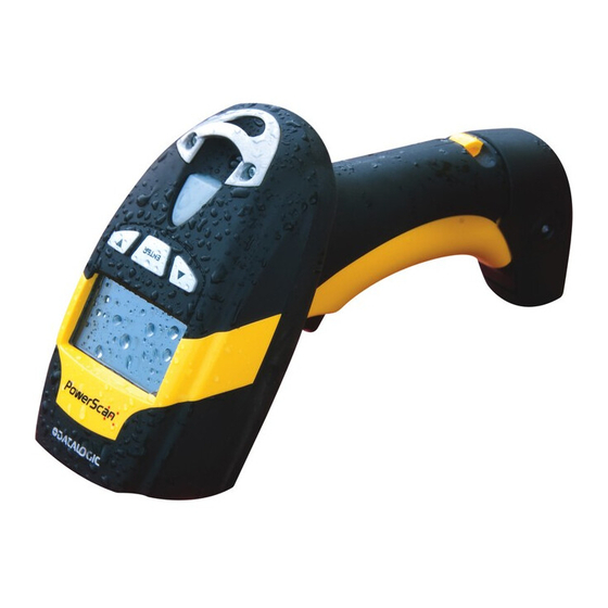
Page 19: General View
Introduction General View ® Powerscan M8500 Readers ® Figure 2. PowerScan M8500 Readers ® Figure 3. PowerScan M8500 Reader with Display PowerScan® M8500... -
Page 20: Bc-80X0 / C-8000 Cradles
General View BC-80X0 / C-8000 CRADLES Figure 4. BC-8000 The label on the cradle contains LED indicators and a scan finder button. When the button is pressed, the cradle transmits a “broadcast” message. All properly configured scanners (Radio RX Timeout set to keep the radio “awake”) linked to that base (through a bind or a join sequence) and within radio range coverage will emit a beep sequence once every 2 seconds for 30 seconds. -
Page 21: Using The Reader
Introduction Using the Reader Aiming System The PowerScan® M8500 reader uses an intelligent aiming system similar to those on cameras. By partially pulling the trigger, the aiming system indicates a field of view to be positioned over the code: Figure 6. Aiming System When you pull the trigger completely a red beam illuminates the code. -
Page 22: Normal Operation
Code Symbols" starting on page Using Datalogic Aladdin™ Datalogic Aladdin™ is a multi-platform utility program providing a quick and user-friendly configuration method via the RS-232/USB-COM interface. Aladdin, available on the CD- ROM provided, allows you to program the reader by selecting configuration commands through a user-friendly graphical interface running on a PC. -
Page 23: Autoscanning
Introduction Autoscanning Normal Mode PowerScan® M8500 provides an autoscan command (see page 205), which when enabled, causes the reader to scan continuously and to monitor the central zone of its reading area. In this way, PowerScan® M8500 is ready to capture any image (containing a potential code) positioned on a uniform background. -
Page 24: Defining Data Formatting
Defining Data Formatting Defining Data Formatting The string of a decoded code to be sent to the host may be formatted as follows: page • defining simple data formatting (see • defining advanced data formatting giving complete flexibility in changing the format of data (see Advanced Data Formatting on page 135). -
Page 25: Concatenation
Introduction Concatenation It is possible to concatenate up to 4 different codes, set their length and enable the Intercode Delay between them (the intercode delay is set in the specific interface parameters, see "Configuration Using Code Symbols" starting on page 53 ). -
Page 26: Powerscan M8500 Setup
Chapter 2 PowerScan M8500 Setup Package Contents The following parts are included in the PowerScan® PM8500 package contents: • PowerScan® PM8500 Hand-Held Reader • CD-ROM containing the PowerScan® PM8500 Configuration Tools software and PowerScan® PM8500 Reference Manual • PowerScan® PM8500 Quick Reference Manual You may want to save your packing material in case you need to ship the reader at some later time. -
Page 27: Rs-232 Connection
PowerScan M8500 Setup RS-232 Connection (If required) IBM USB POS (If required) PowerScan® M8500... -
Page 28: Wedge Connection
Installation WEDGE Connection PEN Emulation Connection Product Reference Guide... -
Page 29: Network Connections
This is possible thanks to the RS-485 connector on the front panel of the cradle. Figure 10. Network Connectors All cradles are connected together within the bus system through the Datalogic RS-485 splitter cable (CAB-428, part number 90A051950), which must be inserted in the RS-485 cradle connector. -
Page 30: Network Termination
Network Connections When wiring the multidrop cables, note the following: • Pin 8 (or 7) can be connected only if the power has to be propagated from a cradle to a STARGATE™ base station or STAR-Box™ converter via the cable. •... -
Page 31: Powerscan® M8500 Battery Maintenance
PowerScan M8500 Setup ® PowerScan M8500 Battery Maintenance Battery Charging ® Once the system is connected and powered, you can place the PowerScan M8500 into the cradle to charge the battery. When the reader is correctly inserted in the cradle, the "Reader" red LED on the cradle goes on to indicate that the battery is charging. - Page 32 Always charge the battery at 32° – 104°F (0° - 40°C) temperature range. Use only the authorized power supplies, battery pack, chargers, and docks supplied by your Datalogic reseller. The use of any other power supplies can damage the device and void your warranty.
-
Page 33: Mounting The Bc-80X0 / C-8000 Cradle
PowerScan M8500 Setup Mounting The BC-80X0 / C-8000 Cradle The cradle package contains the following items: • BC-80X0 / C-8000 Cradle • BC-80X0 Quick Reference / C-8000 Quick Reference • BC-8000 Antenna • 2 wall-mounting lock hinges • 2 adhesive strips •... -
Page 34: Desktop Mounting
PowerScan® M8500 Battery Maintenance Desktop Mounting For desktop usage, you can mount the cradle either on the horizontal base, for reduced overall dimensions, or on the inclined base for a more ergonomic removal and insertion of the reader onto the cradle. Figure 14. -
Page 35: Fixed Desktop Use
PowerScan M8500 Setup Fixed Desktop Use For fixed desktop installation, use the adhesive strips or fixing screws (not provided) according to your needs. For mounting with adhesive strips: 1. Position the cradle onto the base by sliding it along the mounting tabs until aligned. -
Page 36: Wall Mounting
PowerScan® M8500 Battery Maintenance Wall Mounting 1. Remove the yellow caps and insert the two wall mounting lock hinges provided with your cradle. 2. Position the cables to be connected to the BC-80X0/C-8000 cradle along the dedi- cated channels (see figures on page 32.) 3. - Page 37 PowerScan M8500 Setup Figure 16. Inclined Base Wall-Mounting 4. Attach the cradle on the base by sliding it along the mounting tabs until aligned. 5. If mounting the BC-80X0 cradle, insert the antenna in the appropriate hole on the body of the cradle and screw it clockwise until tight.
-
Page 38: System And Network Layouts
System and Network Layouts System and Network Layouts Stand-Alone Layouts Figure 17. Point-to-Point Reader Layout Figure 18. Stand-Alone Layout with Multiple Readers ® M8500 PowerScan M8300 JOIN BIND Host BC-80X0 In stand-alone systems, each cradle is connected to a single Host. Product Reference Guide... -
Page 39: Multiple Stand-Alone Layouts
PowerScan M8500 Setup Multiple Stand-Alone Layouts Many stand-alone connections can operate in the same physical area without interference, provided all readers and cradles in the system have different addresses. Figure 19. Multiple Stand-alone Systems in the Same Area ® Since the cradles can communicate to multiple PowerScan... -
Page 40: Multidrop Star-System™ Network Layouts
The Slaves at the ends of the network must be terminated (reference the STARGATE™ and STAR-Box™ Installation Manuals and "Network Termination" on page 27). "PowerScan® M8500/STAR-System™ Setup" on page 43 and "BC-8060 STAR-System™ Network Setup" on page 45, or the Datalogic Aladdin™ Help On-Line, for system configuration specifications. Product Reference Guide... -
Page 41: Bc-8060 Master Layout
27). See "PowerScan® M8500/STAR-System™ Setup" on page and "BC-8060 STAR- System™ Network Setup" on page 45, or the Datalogic Aladdin™ Help On-Line, for system configuration specifications. Master BC-8060 Network Troubleshooting Two diagnostic strings can be sent via RS-232 from the Host to the Master cradle in order to have feedback about the network itself. -
Page 42: Setup Procedures
Setup Procedures Setup Procedures ® For PowerScan M8500 Series readers, the setup procedures depend on two basic applications, Stand-alone or STAR-System™. Stand-alone applications allow communication with the Host by either the BC-80X0 cradle (page 40), or by the STAR-Modem™ radio modem (page 42). -
Page 43: Powerscan M8500/Bc-80X0 Stand-Alone Setup
PowerScan M8500 Setup Firmly position the reader onto the cradle within 10 seconds, a beep will be emitted, signaling ® that the BC-80X0 cradle has been paired to the PowerScan M8500, and the green LED on the reader will go off. - Page 44 Setup Procedures Set Radio Address ® four digits for the PowerScan M8500 Address (from 0000 to 1999). All readers used in the same area must have different addresses. Exit and Save Configuration ® Read the Bind code to pair the PowerScan M8500 to the BC-80X0 cradle.
-
Page 45: Using Multiple M-Series Readers With Same Cradle
PowerScan M8500 Setup Using Multiple M-Series Readers with Same Cradle If you want to use several M-Series readers with the same BC-80X0 cradle, you must first Bind the cradle with one of the readers (see previously described configuration procedure). Successive readers... -
Page 46: Powerscan® M8500/Star-System™ Setup
Setup Procedures ® PowerScan M8500/STAR-System™ Setup ® The following procedure allows configuring a PowerScan M8500 reader to communicate with various STAR-System™ devices such as STARGATE™ RF base stations. ® Restore PowerScan M8500 Default Enter Configuration Set Date six digits for Day, Month and Year (DDMMYY) Set Time four digits for Hour and Minutes (HHMM) Set the connection according to the length of the codes to be read:... - Page 47 PowerScan M8500 Setup Set Radio Address four digits from the Numeric Table in the range 0000-1999. All readers must have different addresses. First STAR-System™ Address Read the code above and the four-digit address of the First STAR-System™ device in the system.
-
Page 48: Bc-8060 Star-System™ Network Setup
Setup Procedures BC-8060 STAR-System™ Network Setup When the BC-8060 cradle model is used in an RS-485 network, it must be initially configured. To do this using configuration barcodes, follow the procedure below using any ® PowerScan M8500 reader. Set BC-8060 Address four digits for the BC-8060 Address (from 0000 to 1999). - Page 49 For BC-8060 Master Network Layouts (see page 38), the network configuration parameters can be changed either through the Datalogic Aladdin™ configuration software running on the PC or by reading the barcode selections in the Network section of this manual starting on page 79.
-
Page 50: Interface Selection
Interface Selection Interface Selection Read the interface selection code for your application. RS-232 Standard POS TERMINALS Nixdorf Mode A Fujitsu ICL Mode For POS terminal default settings refer to page 174. Product Reference Guide... -
Page 51: Wedge
PowerScan M8500 Setup WEDGE IBM AT or PS/2 PCs IBM XT PC Notebook IBM SURE1 IBM Terminal 3153 IBM TERMINALS 31XX, 32XX, 34XX, 37XX: To select the interface for these IBM Terminals, read the correct KEY TRANSMISSION code. Select the KEYBOARD TYPE if necessary (default = advanced keyboard). -
Page 52: Alt Mode
Interface Selection WEDGE (continued) KEYBOARD TYPE advanced keyboard typewriter keyboard ALT MODE The ALT-mode selection allows barcodes sent to the PC to be interpreted correctly independently from the Keyboard Nationality used. You do not need to make a Keyboard Nationality selection. -
Page 53: Digital Terminals
Load drivers from the O.S. (if requested). When configuring the USB-COM interface, the relevant files and drivers must be installed from the USB Device Installation software, which can be downloaded from the web page http://www.scanning.datalogic.com. The device is ready. Successive start-ups will automatically recognize the previously loaded drivers. -
Page 54: Usb Parameters
USB Parameters USB-KBD USB-KBD-ALT-MODE USB-KBD-APPLE USB-COM* USB-IBM-Table Top USB-IBM-Hand Held * When configuring USB-COM, the relevant files and drivers must be installed from the USB Device Installation software, which can be downloaded from the web site http://www.scanning.datalogic.com. Product Reference Guide... - Page 55 PowerScan M8500 Setup NOTES PowerScan® M8500...
-
Page 56: Configuration Using Code Symbols
Chapter 3 Configuration Using Code Symbols This section provides programming barcodes to configure your reader by changing the "Configuration default settings. For details about additional methods of programming, see Methods" on page You must first enable your reader to read barcodes in order to use this Setup Procedures, starting on section. -
Page 57: Reading Configuration Barcodes
Configuration Using Code Symbols Reading Configuration Barcodes You must first enable your reader to read barcodes in order to use this Setup Procedures, starting on section. If you have not done this, go to page 39 and complete the appropriate procedure. To configure your reader: 1. -
Page 58: Rs-232 Parameters
RS-232 PARAMETERS ® PowerScan M8500/BC-80X0 configurations only Baud Rate on page 56 Parity on page 56 Data Bits on page 57 Stop Bits on page 57 Handshaking on page 57 ACK/NACK Protocol on page 58 FIFO on page 58 Inter-character Delay on page 58 1. -
Page 59: Baud Rate
Enter Reader Configuration Exit and Save Reader Configuration RS-232 PARAMETERS Baud Rate 300 baud 600 baud 1200 baud 2400 baud 4800 baud 9600 baud 19200 baud 38400 baud Parity none even parity odd parity PowerScan® M8500... -
Page 60: Data Bits
Enter Reader Configuration Exit and Save Reader Configuration RS-232 PARAMETERS Data Bits 7 bits 8 bits 9 bits Stop Bits 1 stop bit 2 stop bits Handshaking disable hardware (RTS/CTS) software (XON/XOFF) RTS always ON "Handshaking" on page 155 for details. -
Page 61: Ack/Nack Protocol
Enter Reader Configuration Exit and Save Reader Configuration RS-232 PARAMETERS ACK/NACK Protocol disable enable "ACK/NACK Protocol" on page 156 for details on implementing this parameter with PowerScan® M8500. FIFO disable enable "FIFO" on page 156 for more information. Inter-character Delay delay between characters transmitted to Host ... -
Page 62: Rx Timeout
Enter Reader Configuration Exit and Save Reader Configuration RS-232 PARAMETERS RX Timeout timeout control in reception from Host Read 2 numbers from the Hex & Numeric Table where: 00 = TIMEOUT disabled 01-99 = TIMEOUT from .1 to 9.9 seconds ... -
Page 63: Usb Parameters
USB PARAMETERS USB-COM Handshaking on page 61 ACK/NACK Protocol on page 61 FIFO on page 61 Inter-character Delay on page 62 RX Timeout on page 62 Serial Trigger Lock on page 63 USB-KBD Keyboard Nationality on page 64 FIFO on page 65 Inter-character Delay on page 66 Inter-code Delay on page 66 USB Keyboard Speed on page 66... -
Page 64: Usb-Com
Enter Reader Configuration Exit and Save Reader Configuration USB PARAMETERS USB-COM Handshaking disable hardware (RTS/CTS) software (XON/XOFF) RTS always ON "Handshaking" on page 155 for details. ACK/NACK Protocol disable enable "ACK/NACK Protocol" on page 156 for details on implementing this parameter with PowerScan®... -
Page 65: Inter-Character Delay
Enter Reader Configuration Exit and Save Reader Configuration USB PARAMETERS USB-COM (cont) Inter-character Delay delay between characters transmitted to Host Read 2 numbers from the Hex & Numeric Table where: 00 = DELAY disabled 01-99 = DELAY from 1 to 99 milliseconds ... -
Page 66: Serial Trigger Lock
Enter Reader Configuration Exit and Save Reader Configuration USB PARAMETERS USB-COM (cont) Serial Trigger Lock disabled enable and select characters Read 2 characters from the Hex & Numeric Table in the range 00-FE where: • First Character enables device trigger •... -
Page 67: Usb-Kbd
Enter Reader Configuration Exit and Save Reader Configuration USB PARAMETERS USB-KBD Keyboard Nationality Not Available for USB-KBD-ALT-MODE Interface. This parameter default value is restored through the Interface Selection code and not Restore Default. Belgian English (UK) French German Italian Spanish Swedish ... -
Page 68: Fifo
Enter Reader Configuration Exit and Save Reader Configuration USB PARAMETERS USB-KBD (cont) The Japanese and Eastern Block Keyboard Nationality selections are valid only for IBM AT compatible PCs. Japanese Russian (Latin) Russian (Cyrillic) Hungarian Slovenian, Croatian, Serbian (Latin) Romanian Czech Republic FIFO disable ... -
Page 69: Inter-Character Delay
Enter Reader Configuration Exit and Save Reader Configuration USB PARAMETERS USB-KBD (cont) Inter-character Delay delay between characters transmitted to Host Read 2 numbers from the Hex & Numeric Table where: 00 = DELAY disabled 01-99 = DELAY from 1 to 99 milliseconds ... -
Page 70: Wedge Parameters
WEDGE PARAMETERS ® PowerScan M8500/BC-80X0 configurations only Keyboard Nationality on page 68 Caps Lock on page 69 Caps Lock Auto-Recognition (IBM AT compatible only) on page 70 Num Lock on page 70 Inter-character Delay on page 70 Inter-code Delay on page 71 Keyboard Setting on page 71 Control Character Emulation on page 1. -
Page 71: Keyboard Nationality
Enter Reader Configuration Exit and Save Reader Configuration WEDGE PARAMETERS Keyboard Nationality Belgian English (UK) French German Italian Spanish Swedish USA PowerScan® M8500... -
Page 72: Caps Lock
Enter Reader Configuration Exit and Save Reader Configuration WEDGE PARAMETERS The Japanese and Eastern Block Keyboard Nationality selections are valid only for IBM AT compatible PCs. Japanese Russian (Latin) Russian (Cyrillic) Hungarian Slovenian, Croatian, Serbian (Latin) Romanian Czech Republic Caps Lock ... -
Page 73: Caps Lock Auto-Recognition (Ibm At Compatible Only)
Enter Reader Configuration Exit and Save Reader Configuration WEDGE PARAMETERS Caps Lock Auto-Recognition (IBM AT compatible only) disable enable Num Lock toggle num lock num lock unchanged This selection is used together with the Alt Mode interface selection for AT or Notebook PCs. -
Page 74: Inter-Code Delay
Enter Reader Configuration Exit and Save Reader Configuration WEDGE PARAMETERS Inter-code Delay delay between codes transmitted to Host Read 2 numbers from the Hex & Numeric Table where: 00 = DELAY disabled 01-99 = DELAY from 1 to 99 milliseconds ... - Page 75 Enter Reader Configuration Exit and Save Reader Configuration WEDGE PARAMETERS Some ASCII characters may be missing as this depends on the type of keyboard: these are generally particular characters relative to the various national symbologies. In this case: • The first 4 characters (Shift, Alt, Ctrl, and Backspace) can only be substituted with keys not used, or substituted with each other.
-
Page 76: Control Character Emulation
Enter Reader Configuration Exit and Save Reader Configuration WEDGE PARAMETERS Control Character Emulation Ctrl + Shift + Key Ctrl + Key Product Reference Guide... -
Page 77: Pen Emulation
PEN EMULATION ® PowerScan M8500/BC-80X0 configurations only Operating Mode on page 75 Minimum Output Pulse on page 76 Conversion to Code 39 on page 76 Overflow on page 77 Output Level on page 77 Idle Level on page 78 Inter-Block Delay on page 78 1. -
Page 78: Operating Mode
Operating Mode The operating mode parameters are complete commands and do not require reading the Enter and Exit configuration codes. interpret mode Interprets commands without sending them to the decoder. transparent mode Sends commands to the decoder without interpreting them. Product Reference Guide... -
Page 79: Minimum Output Pulse
Enter Reader Configuration Exit and Save Reader Configuration PEN EMULATION Minimum Output Pulse high resolution code emulation 200 s 400 s 600 s 800 s 1 ms 1.2 ms low resolution code emulation "Minimum Output Pulse" on page 157 for details. -
Page 80: Conversion To Code 128
Enter Reader Configuration Exit and Save Reader Configuration PEN EMULATION Conversion to Code 128 enable conversion to Code 128 Converts codes read into Code 128 format. "Conversion to Code 39 and Code 128" on page 157 for details. Overflow narrow ... -
Page 81: Idle Level
Enter Reader Configuration Exit and Save Reader Configuration PEN EMULATION Idle Level normal inverted (black level) (white level) "Output and Idle Levels" on page 158 for details. Inter-Block Delay delay between character blocks transmitted to Host Read 2 numbers from the Hex & Numeric Table where: 00 = DELAY disabled 01-99 =... -
Page 82: Network Parameters
NETWORK PARAMETERS BC-8060 model configurations only RS-485 Network on page 80 Network Baud Rate on page 80 Slave Address Range on page 81 Network Warning Message on page 81 Reception Warning Message on page 81 Master Cradle Header on page 82 Master Cradle Terminator on page 83 1. -
Page 83: Network
Enter Reader Configuration Exit and Save Reader Configuration NETWORK PARAMETERS RS-485 Network disable RS-485 network enable RS-485 slave enable RS-485 master "Multidrop STAR-System™ Network Layouts" on page 37 for details. If a BC-8060 cradle is errantly configured as a Slave but not connected to a network, it may not be able to receive further commands from the reader. -
Page 84: Slave Address Range
Enter Reader Configuration Exit and Save Reader Configuration NETWORK PARAMETERS Slave Address Range First Address Read the code above and the four-digit address of the First Slave device in the system. Last Address Read the code above and the four-digit address of the Last Slave device in the system. "Slave Address Range First/Last"... -
Page 85: Master Cradle Header
Enter Reader Configuration Exit and Save Reader Configuration NETWORK PARAMETERS Master Cradle Header no header one character header two character header three character header four character header five character header six character header seven character header ... -
Page 86: Master Cradle Terminator
Enter Reader Configuration Exit and Save Reader Configuration NETWORK PARAMETERS Master Cradle Terminator no terminator one character terminator two character terminator three character terminator four character terminator five character terminator six character terminator seven character terminator ... -
Page 87: Data Format
DATA FORMAT NOT FOR PEN INTERFACES Symbology Independent Parameters Code Identifier on page 85 Custom Code Identifier on page 86 Header on page 89 Terminator on page 90 Code Length Tx on page 91 Address Stamping on page 91 Address Delimiter on page 92 Time Stamping on page 92 Time Stamping Delimiter on page 93 1. -
Page 88: Code Identifier
Enter Reader Configuration Exit and Save Reader Configuration DATA FORMAT Code Identifier disable Datalogic standard AIM standard custom Product Reference Guide... -
Page 89: Custom Code Identifier
Enter Reader Configuration Exit and Save Reader Configuration DATA FORMAT Custom Code Identifier The following procedure sets a new Code Identifier for a specific barcode symbology: 1. Read the Enter Reader Configuration code at the top of the page. 2. Read one of the following codes that corresponds to the required barcode symbology. 3. - Page 90 Enter Reader Configuration Exit and Save Reader Configuration DATA FORMAT Custom Code Identifier — continued CODE 32 PDF 417 MICRO PDF 417 MAXICODE DATAMATRIX QR CODE MICRO QR AZTEC AUSTRALIAN POSTAL INTELLIGENT MAIL BARCODE ...
- Page 91 Enter Reader Configuration Exit and Save Reader Configuration DATA FORMAT Custom Code Identifier — continued PLANET POSTAL POSTNET POSTAL KIX POSTAL RM4SCC POSTAL GS1 DATABAR PowerScan® M8500...
-
Page 92: Header
Enter Reader Configuration Exit and Save Reader Configuration DATA FORMAT Header no header one character header two character header three character header four character header five character header six character header seven character header ... -
Page 93: Terminator
Enter Reader Configuration Exit and Save Reader Configuration DATA FORMAT Terminator no terminator one character terminator two character terminator three character terminator four character terminator five character terminator six character terminator seven character terminator ... -
Page 94: Code Length Tx
Enter Reader Configuration Exit and Save Reader Configuration DATA FORMAT Code Length Tx code length not transmitted code length transmitted in variable-digit format code length transmitted in fixed 4-digit format The code length is transmitted in the message after the Headers and Code Identifier characters. -
Page 95: Address Delimiter
Enter Reader Configuration Exit and Save Reader Configuration DATA FORMAT Address Delimiter disable reader address delimiter disable cradle address delimiter enable reader address delimiter and select characters enable cradle address delimiter and select characters Read 2 HEX characters in the range 00-FE ... -
Page 96: Time Stamping Delimiter
Enter Reader Configuration Exit and Save Reader Configuration DATA FORMAT Time Stamping Delimiter disable select delimiter Read 2 HEX characters in the range 00-FE. "Time Stamping Delimiter" on page 168 for details. Product Reference Guide... -
Page 97: Symbology Dependent Parameters
Symbology Dependent Parameters Symbology Dependent Parameters Symbology Specific Format on page 95 Symbology Headers on page 95 Headers on page 96 Symbology Terminators on page 96 Terminators on page 96 Symbology Character Substitution on page 97 Character Substitution on page 97 Symbology Character Deletion on page 97 Character Deletion on page 98 Symbology Specific Format Default on page 98... -
Page 98: Symbology Specific Format
AKCBPJCJGIIJCMCFHLNMJCGPLK AEFBJLBGMHPLMMGPEPDOAPMGGK AAPHBAJJDCFMDNCMBONAPKCNHK AGKFALICLLGKIBEJGFOCKENJLK DLLLLLDLLLDLLLLDDLDDDLDLLL 1. Select a Datalogic Standard Code Identifier from the Code Identifier Table in Appendix 2. Formatting: 0 = select all - Stop 1 = select right - followed by Step 3 2 = select left - followed by Step 3... -
Page 99: Headers
DATA FORMAT Headers Headers AOCPFPHMFNGNENEIEPANHOGOCK AHPNIJAMDKEOFMHMLJALEBGEIK AKCBPJCJGIIJCMCFHKPEEAKDLK AEFBJLBGMHPKNPAPMMGMNIIHGK AAPHBAJIDDEICPPPODIOCPCPHK AELFANOCPAJCGLHLEJKOEMJJLK DLLLLDLDLLDLLLLDLLDDDLDLLL 1. Select a Datalogic Standard Code Identifier from the Code Identifier Table in Appendix 2. 0 = disabled 1 = enabled Symbology Terminators Symbology Terminators AOCPFLHMHNGNENEIEPANHOGOCK AHPNIJAMDKEOFMHMLJAKFGAGIK AKCBPJCJGIIJCMCFGONFOBJDNK AEFBJLBGMHPKNNEAEHPKOFLEGK... -
Page 100: Symbology Character Substitution
AAPHBAJJDCFDBILOKBFBDLPDDK AHKFAINIMEHCEPHBKFHEKPGIIK DLLLLDLDDLDLLLLDLDDDDLDLLL 1. Select a Datalogic Standard Code Identifier from the Code Identifier Table in Appendix 2. Read the corresponding character as Hex value from the Hex/Numeric table which identifies the character to be substituted. Valid value is in the range 00-7F. -
Page 101: Character Deletion
Character Deletion AOCLFPHMFNGNENEIEPANHOGOCK AHPNIJAMDKEOFMHMLJALFECHIK AKCBPJCJGIIJCMCFHOOJDDAJLK AEFBJLBGMHPLNPEOIFPJKFDFGK AAPHBAJJCCFHCMBKKMPIKJFFBK AEKFAONABANMAJILDPBGECLIIK DDLLLDLDLDLLLLLDDDLDDLDLDL 1. Select a Datalogic Standard Code Identifier from the Code Identifier Table in Appendix 2. 0 = disabled 1 = enabled Symbology Specific Format Default Symbology Specific Format Default AOCPBLDIHNGNENEIEPANHOGOCK AHPNIJAMDKEOFMHMLJALFAAEIK... -
Page 102: Concatenation
AGLFALMAEMIEEPDCHHBIGEDLLK DLLLLDLDLLLLLLLDLLDDDLDLDL 1. Select the number of codes to concatenate in the range 2-4. 2. Select the Datalogic Standard Code Identifier for each code to concatenate (repeat for Appendix same code types) from the table in 3. Read the following code to enable the configuration you have set. -
Page 103: Third Concatenated Code Length
Enter Reader Configuration Exit and Save Reader Configuration DATA FORMAT Third Concatenated Code Length Set Third Concatenated Code Length AOCLCKHOBNGNENEIEPANHOGOCK AHHPEJIMDKEOFMHMLJAKFBGEIK AKCBPJCJGIIJCMCEHIKFCDNJJK AEFBJLBGMHPKNJCDOEAJJBHHGK AAPHBAJJDACEMAALKPDBBFPLDK AEKFALJPMALEIHOBMOIIEPNJKK DLLLLDLDLDLLLLLDLLLDDLDLLL Read the number in the range 000-255. 000 = any code length Fourth Concatenated Code Length Set Fourth Concatenated Code Length AOCLCKHOBNGNENEIEPANHOGOCK AHHPEJAMDKEOFMHMLJALEEGGIK... -
Page 104: Transmission After Timeout
Enter Reader Configuration Exit and Save Reader Configuration DATA FORMAT Transmission After Timeout No Code Transmission First Code Transmission AOCLCKFOFNGNENEIEPANHOGOCK AOCLCKFOFNGNENEIEPANHOGOCK AHHPMJAMDKEOFMHMLJALFDEGIK AHHPMBIMDKEOFMHMLJALFFGFIK AKCBPJCJGIIJCMCFHOIJLDLHLK AKCBPJCJGIIJCMCFGPLFBMAJNK AEFBJLBGMHPLNJHPPIEKCAFEGK AEFBJLBGMHPLNOALANDGIGOFGK AAPHBAJJDEGMKJKMAAALNIONFK AAPHBAJJCHCLPAADONEHLAIPDK AGKFAKJDBHEIEJNLFPPGCJBLKK AHKFAPIKNBHOODJOPKIKKAGKIK DLDLLDLDDLLLLLLDLDDDDLDLDL DLDLLDLDDLLLLLLDDDDDDLDLDL Second Code Transmission Third Code Transmission AOCLCKFOFNGNENEIEPANHOGOCK AOCLCKFOFNGNENEIEPANHOGOCK AHHPMBAMDKEOFMHMLJAKEAGHIK AHHPEJIMDKEOFMHMLJALEEBGIK... -
Page 105: Camera Control
Enter Reader Configuration Exit and Save Reader Configuration CAMERA CONTROL CAMERA CONTROL Exposure Mode Automatic (Entire Image) AOCKCKHMHNGNENEIEPANHOGOCK AHHPMBIMDKEOFMHMLJAKEGCEIK AKCBPJCJGIIJCMCEGMJHKBKNNK AEFBJLBGMHPLNPAICDABCGHGGK AAPHBAJJCDFOOPCEHFCEBHJFFK AHKFAJMFIHDMKONFFAOAGCPJKK DLDLLLLDDLLLLLLDDDLDDLDLLL Automatic for Highly Automatic (Central Part of Image) Reflective Surfaces AOCKCKHMHNGNENEIEPANHOGOCK AOCKCKHMHNGNENEIEPANHOGOCK AHHPMBAMDKEOFMHMLJALFDCGIK AHHPEJIMDKEOFMHMLJAKFHFHIK AKCBPJCJGIIJCMCFHKNMCDFPJK AKCBPJCJGIIJCMCFGPJNEICLPK AEFBJLBGMHPKMPHMPBJJGKOEGK AEFBJLBGMHPLNLEFGIMLPOKFGK AAPHBAJIDHBGOKMGCKDFPOGLBK... -
Page 106: Aiming System
Enter Reader Configuration Exit and Save Reader Configuration AIMING SYSTEM AIMING SYSTEM "Aiming System" on page 18 for more information. disable Aiming System enable Aiming System Good Read Spot A green Good-Read Spot will be projected in the field of view when the reading is successful. -
Page 107: Code Selection
Enter Reader Configuration Exit and Save Reader Configuration CODE SELECTION CODE SELECTION Disable All Symbologies Disable All Linear Symbologies APCPCKHMHNGNENEIEPANHOGOCK APCPGKHMHNGNENEIEPANHOGOCK AHHPMJAMDKEOFMHMLJAKFHEHIK AHHPMJAMDKEOFMHMLJAKFBCHIK AKCBPJCJGIIJCMCEHPIFJNCLPK AKCBPJCJGIIJCMCEHKPMGLHBNK AEFBJLBGMHPKNPEHGMLHNABFGK AEFBJLBGMHPKMIHDGICIAJMGGK AAPHBAJICFBOAJJGCKPDGADNBK AAPHBAJIDBDPPIKJPJAMPIPNDK AEKFAPJAJPBAEIBFNOAIKGGIKK AHKFAOKLLANCKCDCCIECCDLKKK DLDLDDLDDDLLLLLDDLLDDLDLLL DDLLDDLDLLDLLLLDDLDDDLDLDL Disable All 2D Symbologies APCPCOHMHNGNENEIEPANHOGOCK AHHPMJAMDKEOFMHMLJALFFCFIK AKCBPJCJGIIJCMCFHIOCODMJNK AEFBJLBGMHPKNPDAMNNPKGLEGK AAPHBAJJCAGEAGOFFMPMIIJHBK AFLFALLLOMIKOEILGAEMAFDJJK... -
Page 108: Linear Symbologies
Enter Reader Configuration Exit and Save Reader Configuration CODE SELECTION Linear Symbologies Linear Symbologies UPC/EAN/JAN Family on page 105 Code 39 Family on page 106 Code 32 Family on page 107 Interleaved 2 of 5 Family on page 107 Codabar Family on page 108 Code 128 Family on page 109 Code 93 Family on page 110 GS1 Databar™... -
Page 109: Code 39 Family
Enter Reader Configuration Exit and Save Reader Configuration CODE SELECTION Code 39 Family Code 39 Std - Disabled Code 39 Std - No Check Digit Control APCPCKHMHNGNENEIEPANHOGOCK APCPCKHMHNGNENEIEPANHOGOCK AHHPMJAMDKEOFMHMLJAKEACHIK AHHPMBIMDKEOFMHMLJAKEGAEIK AKCBPJCJGIIJCMCEHMOOACIBLK AKCBPJCJGIIJCMCEGNNCKNDPNK AEFBJLBGMHPLNJFIOHOGPCCEGK AEFBJLBGMHPLNOCMBCJKFEJFGK AAPHBAJJCHACGHGINLINEBBHHK AAPHBAJJDEEFDOMHDGMBCJHFBK AFKFAKJMEMGGGAJIEDJCKCIJIK AEKFAPIFIKFAMKNNOGOOCLPIKK DDLLLLLDLDDLLLLDDLLDDLDLLL DDLLLLLDLDDLLLLDLLLDDLDLLL Code 39 Std - Check Digit Control Code 39 Std - Check Digit Control without Transmission... -
Page 110: Code 32 Family
Enter Reader Configuration Exit and Save Reader Configuration CODE SELECTION Code 39 Family (continued) Start-Stop Character Transmission - Start-Stop Character Transmission - Disabled Enabled APCPCKFMFNGNENEIEPANHOGOCK APCPCKFMFNGNENEIEPANHOGOCK AHHPMJAMDKEOFMHMLJAKEFHFIK AHHPMBIMDKEOFMHMLJAKEDFGIK AKCBPJCJGIIJCMCEHKILHLJNPK AKCBPJCJGIIJCMCEGLLHNECDJK AEFBJLBGMHPLMPCGALLLNPBEGK AEFBJLBGMHPLMIFCPOMHHJKFGK AAPHBAJIDEEJKEGNNDDELPNDBK AAPHBAJICHAOPNMCDOHINHLBHK AGLFAIPCDCNEKFGNDNJACOOIIK AHLFANOLPEOCAPCIJIOMKHJJKK DLLLLLLDDDDLLLLDDDDDDLDLLL DLLLLLLDDDDLLLLDLDDDDLDLLL Code 32 Family Disabled Enabled APCPCKFOBNGNENEIEPANHOGOCK... -
Page 111: Codabar Family
Enter Reader Configuration Exit and Save Reader Configuration CODE SELECTION Interleaved 2 of 5 Family (continued) Maximum Code Length APCLFPFOFNGNENEIEPANHOGOCK AHPNIJAMDKEOFMHMLJAKEHAFIK Read the number in the range AKCBPJCJGIIJCMCFGLNFCOEHPK AEFBJLBGMHPKNNBAPJDOEBGFGK 001-255. AAPHBAJIDAGGCIDGNPCHNCGDDK AGLFANMHMDAECAILPBBOACHJJK DLDLLLLDLLLLLLLDLDDDDLDLDL Codabar Family Disabled Enabled - No Check Digit Control APCLGKHMHNGNENEIEPANHOGOCK APCLGKHMHNGNENEIEPANHOGOCK AHHPMJAMDKEOFMHMLJAKFDAEIK... -
Page 112: Code 128 Family
Enter Reader Configuration Exit and Save Reader Configuration CODE SELECTION Code 128 Family Code 128 - Disabled Code 128 - Enabled APCPCOHMHNGNENEIEPANHOGOCK APCPCOHMHNGNENEIEPANHOGOCK AHHPMJAMDKEOFMHMLJALECEFIK AHHPMBIMDKEOFMHMLJALEEGGIK AKCBPJCJGIIJCMCFHLIJHMGDJK AKCBPJCJGIIJCMCFGKLFNDNNPK AEFBJLBGMHPLNOFLLDPCCCDEGK AEFBJLBGMHPLNJCPEGIOIEIFGK AAPHBAJICCHIGIBLKNICKJLNHK AAPHBAJIDBDPDBLEEAMOMBNPBK AELFAOLHDPPMMMAGPNNGABNILK AFLFALKOPJMKGGEDFIKKIIKJJK DDDLLLLDDDLLLLLDLDLDDLDLDL DDDLLLLDDDLLLLLDDDLDDLDLDL Code Length Check - Disabled Code Length Check - Enabled APCPCOHMFNGNENEIEPANHOGOCK APCPCOHMFNGNENEIEPANHOGOCK... -
Page 113: Code 93 Family
Enter Reader Configuration Exit and Save Reader Configuration CODE SELECTION Code 128 Family (continued) EAN 128 - Min. Code Length APCPFPFOHNGNENEIEPANHOGOCK AHPNIJAMDKEOFMHMLJALEHBHIK Read the number in the range AKCBPJCJGIIJCMCEHNPCDHEFNK AEFBJLBGMHPKMNGCIACDDNNFGK 001-255. AAPHBAJJDCBLLIAMCCGFHECLBK AFKFAILBIEHKAHANMBAIGMJIJK DDDLDLLDLDDLLLLDLDLDDLDLLL Maximum Code Length APCPFPFOFNGNENEIEPANHOGOCK AHPNIJAMDKEOFMHMLJALFCBHIK Read the number in the range AKCBPJCJGIIJCMCFGOLEOIJHJK AEFBJLBGMHPKMPFKKKNNHGEHGK 001-255. -
Page 114: Gs1 Databar™ Family
Enter Reader Configuration Exit and Save Reader Configuration CODE SELECTION GS1 Databar™ Family Disable GS1 DataBar Expanded Enable GS1 DataBar Expanded APCLCOHMHNGNENEIEPANHOGOCK APCLCOHMHNGNENEIEPANHOGOCK AHHPMJAMDKEOFMHMLJAKEADHIK AHHPMBIMDKEOFMHMLJAKEGBEIK AKCBPJCJGIIJCMCFHNIDCFBJLK AKCBPJCJGIIJCMCFGMLPIKKHNK AEFBJLBGMHPKMNHKJODMJBJGGK AEFBJLBGMHPKMKAOGLEADHCHGK AAPHBAJIDCFJFPNCEGJBEKGJFK AAPHBAJICBBOAGHNKLNNCCALDK AHKFAOOHMDEMKBLOPEIOKOKKJK AGKFALPOAFHKALPLFBPCCHNLLK DLLLLDLDDDLLLLLDDDLDDLDLLL DLLLLDLDDDLLLLLDLDLDDLDLLL Disable GS1 DataBar Limited Enable GS1 DataBar Limited APCLCOHMFNGNENEIEPANHOGOCK APCLCOHMFNGNENEIEPANHOGOCK AHHPMJAMDKEOFMHMLJAKFFDHIK... -
Page 115: 2D Symbologies
Enter Reader Configuration Exit and Save Reader Configuration CODE SELECTION 2D Symbologies 2D Symbologies PDF417 on page 112 Micro PDF417 on page 113 DataMatrix Family on page 113 QR Family on page 113 Postal Codes Family on page 114 Australian Table Selection on page 115 Maxicode Family on page 115 Aztec on page 116 Composite Codes on page 116... -
Page 116: Micro Pdf417
Enter Reader Configuration Exit and Save Reader Configuration CODE SELECTION Micro PDF417 Disabled Enabled APCPGOHMFNGNENEIEPANHOGOCK APCPGOHMFNGNENEIEPANHOGOCK AHHPMJAMDKEOFMHMLJAKEGBEIK AHHPMBIMDKEOFMHMLJAKEADHIK AKCBPJCJGIIJCMCEGPKBHPDLNK AKCBPJCJGIIJCMCEHOJNNAIFLK AEFBJLBGMHPLNIDHPJMIHOGFGK AEFBJLBGMHPLNPEDAMLENINEGK AAPHBAJJCHCHGEAFDNDHDAGFHK AAPHBAJJDEGADNKKNAHLFIAHBK AFLFAMMEGEHIELNKNAKIOACLKK AELFAJNNKCEOOBJPHFNEGJFKIK DDDLLDLDDLLLLLLDDLDDDLDLLL DDDLLDLDDLLLLLLDLLDDDLDLLL DataMatrix Family Disabled Enabled APCPGKHMHNGNENEIEPANHOGOCK APCPGKHMHNGNENEIEPANHOGOCK AHHPMJAMDKEOFMHMLJALFBHGIK AHHPMBIMDKEOFMHMLJALFHFFIK AKCBPJCJGIIJCMCEHLIANOALLK AKCBPJCJGIIJCMCEGKLMHBLFNK AEFBJLBGMHPLNKHIHCFOEDFGGK AEFBJLBGMHPLNNAMIHCCOFOHGK AAPHBAJIDCBNKCHLKMBHLMHJBK AAPHBAJICBFKPLNEEBFLNEBLHK AFKFAIMFHPFKIFPHMKDIIGAIJK... -
Page 117: Micro Qr
Enter Reader Configuration Exit and Save Reader Configuration CODE SELECTION Micro QR Disabled Enabled Postal Codes Family All Disabled Australian Post - Enabled APCLGKHMHNGNENEIEPANHOGOCK APCLGKHMHNGNENEIEPANHOGOCK AHHPMJAMDKEOFMHMLJALEEDFIK AHHPMBIMDKEOFMHMLJALECBGIK AKCBPJCJGIIJCMCEHPJNKNKBLK AKCBPJCJGIIJCMCEGOKBACBPNK AEFBJLBGMHPKNKDJDLMLDOOEGK AEFBJLBGMHPKNNENMOLHJIFFGK AAPHBAJJCDACKBJOODGBDKADHK AAPHBAJJDAEFPIDBAOCNFCGBBK AFLFALPHJPBEOHAHLMIAIICJKK AELFAOOOFJCCENECBJPMABFIIK DDLLLDLDDLLLLLLDLLDDDLDLLL DDLLLDLDDLLLLLLDDLDDDLDLLL Japan Post - Enabled PLANET - Enabled APCLGKHMHNGNENEIEPANHOGOCK APCLGKHMHNGNENEIEPANHOGOCK... -
Page 118: Australian Table Selection
Enter Reader Configuration Exit and Save Reader Configuration CODE SELECTION Australian Table Selection N Table C Table APCLGKHMFNGNENEIEPANHOGOCK APCLGKHMFNGNENEIEPANHOGOCK AHHPMJAMDKEOFMHMLJALFBDFIK AHHPMBIMDKEOFMHMLJALFHBGIK AKCBPJCJGIIJCMCFGMNLHCHDPK AKCBPJCJGIIJCMCFHNOHNNMNJK AEFBJLBGMHPKNIABBBDFHFHGGK AEFBJLBGMHPKNPHFOEEJNDMHGK AAPHBAJJDDECGIJDAEEOFOLFBK AAPHBAJJCAAFDBDMOJACDGNHHK AELFALNNPHKMIFLEBIFEENFLKK AFLFAOMEDBJKCPPBLNCIMECKIK DLLLLDLDLDLLLLLDDLLDDLDLLL DLLLLDLDLDLLLLLDLLLDDLDLLL Intelligent Mail Barcode Disabled Enabled Maxicode Family Maxicode Mode 0 - Disabled Maxicode Mode 0 Enabled APCPCKFOBNGNENEIEPANHOGOCK APCPCKFOBNGNENEIEPANHOGOCK... -
Page 119: Aztec
Enter Reader Configuration Exit and Save Reader Configuration CODE SELECTION Maxicode Family (continued) Maxicode Mode 4 - Disabled Maxicode Mode 4 - Enabled APCPCKHKFNGNENEIEPANHOGOCK APCPCKHKFNGNENEIEPANHOGOCK AHHPMJAMDKEOFMHMLJAKFABGIK AHHPMBIMDKEOFMHMLJAKFGDFIK AKCBPJCJGIIJCMCEHKMLBDCJNK AKCBPJCJGIIJCMCEGLPHLMJHLK AEFBJLBGMHPKMNEBLMNJGGMHGK AEFBJLBGMHPKMKDFEJKFMAHGGK AAPHBAJJDFFEBHJPGPOKHBINDK AAPHBAJJCGBDEODAICKGBJOPFK AHLFAMPHNBIGIDMOGMEMKBKLIK AGLFAJOOBHLACJILMJDACINKKK DLLLLDLDLDLLLLLDLLLDDLDLLL DLLLLDLDLDLLLLLDDLLDDLDLLL Maxicode Mode 5 - Disabled Maxicode Mode 5 - Enabled APCPCKHIHNGNENEIEPANHOGOCK APCPCKHIHNGNENEIEPANHOGOCK... -
Page 120: Reading Parameters
READING PARAMETERS Trigger Mode on page 118 Trigger Type on page 118 Flash Mode on page 118 Beeper Tone on page 118 Beeper Volume on page 119 Beeper Duration on page 119 Reads per Cycle on page 119 Scan Timeout on page 119 User Defined Beeper User Defined Beeper Tone on page 120 User Defined Beeper Volume on page 120... -
Page 121: Trigger Mode
Enter Reader Configuration Exit and Save Reader Configuration READING PARAMETERS Trigger Mode Trigger Level Trigger Pulse APCOCOHMHNGNENEIEPANHOGOCK APCOCOHMHNGNENEIEPANHOGOCK AHHPMJAMDKEOFMHMLJAKEAGGIK AHHPMBIMDKEOFMHMLJAKEGEFIK AKCBPJCJGIIJCMCFGILHGJEHJK AKCBPJCJGIIJCMCFHJILMGPJPK AEFBJLBGMHPLNJAKKIEPNIOFGK AEFBJLBGMHPLNOHOFNDDHOFEGK AAPHBAJJCAHEBANDBIMIMMMLBK AAPHBAJJDDDDEJHMPFIEKEKJHK AEKFALNAJKBEGAIEALHCAKNIJK AFKFAOMJFMCCMKMBKOAOIDKJLK DLLLLLLDLLLLLLLDDLLDDLDLDL DLLLLLLDLLLLLLLDLLLDDLDLDL Trigger Type Normal Trigger Software Trigger APCOCOHMFNGNENEIEPANHOGOCK APCOCOHMFNGNENEIEPANHOGOCK AHHPMJAMDKEOFMHMLJAKFFGGIK AHHPMBIMDKEOFMHMLJAKFDEFIK AKCBPJCJGIIJCMCEHLPBLGJFNK AKCBPJCJGIIJCMCEGKMNBJCLLK AEFBJLBGMHPLNLDCICLBJDHHGK... -
Page 122: Beeper Volume
Enter Reader Configuration Exit and Save Reader Configuration READING PARAMETERS Beeper Volume Beeper OFF Low Volume APDNCKHMFNGNENEIEPANHOGOCK APDNCKHMFNGNENEIEPANHOGOCK AHHPMJAMDKEOFMHMLJALEABGIK AHHPMBIMDKEOFMHMLJALEGDFIK AKCBPJCJGIIJCMCFGJKNDOMDLK AKCBPJCJGIIJCMCFHIJBJBHNNK AEFBJLBGMHPLNNHGFHOILPGHGK AEFBJLBGMHPLNKACKCJEBJNGGK AAPHBAJJDEABIIAFCGBJLGHDHK AAPHBAJJCHEGNBKKMLFFNOBBBK AHKFAOJHOIPOEOGEOGECMGDKKK AGKFALIOCOMIOECBEDDOEPELIK DDDLLLLDLLLLLLLDLDDDDLDLDL DDDLLLLDLLLLLLLDDDDDDLDLDL Medium Volume High Volume APDNCKHMFNGNENEIEPANHOGOCK APDNCKHMFNGNENEIEPANHOGOCK AHHPMBAMDKEOFMHMLJAKFDDHIK AHHPEJIMDKEOFMHMLJALFHEGIK AKCBPJCJGIIJCMCEGONKBDIPJK AKCBPJCJGIIJCMCEHLJLHIPLPK AEFBJLBGMHPKMKHGHAAMFFEEGK AEFBJLBGMHPLNOEPOJFOMBAFGK AAPHBAJIDDAONEEIJEEEDHOPFK... -
Page 123: User Defined Beeper
Enter Reader Configuration Exit and Save Reader Configuration READING PARAMETERS User Defined Beeper In addition to the standard configuration settings for good/wrong reading and indicating errors, the PowerScan® M8500 basic software program can also manage the beeper (User Defined Beeper) when the reader is controlled by a Host PC. The beeper can be activated by a command from the Host to the reader via the current communication interface. -
Page 124: Code Ordering And Selection
Set Order 1. Select the number of codes in APBPBPFOHNGNENEIEPANHOGOCK AHPNIJAMDKEOFMHMLJAKEEAHIK the range 0-9. AKCBPJCJGIIJCMCFGPKMGNENLK AEFBJLBGMHPKNJGKFLAALGHHGK 2. Select the Datalogic Standard AAPHBAJJCFCGFDNNCBIJALKDHK AGLFALNLKIAEAMIJIJEICMAIIK Code Identifier for each above DLLLLLLDLDDLLLLDLDLDDLDLLL defined code from the table in Appendix "Defining Data Formatting" on page 21 for details. -
Page 125: Autoscan
Enter Reader Configuration Exit and Save Reader Configuration READING PARAMETERS Autoscan Autoscan Mode Disabled Enabled in Normal Mode APCOCKHMHNGNENEIEPANHOGOCK APCOCKHMHNGNENEIEPANHOGOCK AHHPMJAMDKEOFMHMLJALECAEIK AHHPMBIMDKEOFMHMLJALEECHIK AKCBPJCJGIIJCMCEGPNABHKFLK AKCBPJCJGIIJCMCEHOOMLIBLNK AEFBJLBGMHPLNJHNAJCHKOEEGK AEFBJLBGMHPLNOAJPMFLAIPFGK AAPHBAJICFAOBPKAGOMHCEGBBK AAPHBAJIDGEJEGAPIDILEMADHK AFLFAPPLOJIOMMBKLFDGKJIJKK AELFAKOCCPLIGGFPBAEKCAPIIK DLDLLLLDDLDLLLLDLDLDDLDLLL DLDLLLLDDLDLLLLDDDLDDLDLLL Enabled in Pattern Mode APCOCKHMHNGNENEIEPANHOGOCK AHHPMBAMDKEOFMHMLJAKFBCFIK AKCBPJCJGIIJCMCFGIKHDKOJJK AEFBJLBGMHPKMOHNCOMDEEGHGK AAPHBAJJCCABEDONNMJKKFPNDK AHLFAJIBHGIIALBHMHCKGFAIJK DLDLLLLDDLDLLLLDLDLDDLDLLL... -
Page 126: Safety Time
Enter Reader Configuration Exit and Save Reader Configuration READING PARAMETERS The following commands can be activated only when One Code per Scan is enabled. Safety Time Disabled Enabled APCOGOHMHNGNENEIEPANHOGOCK APCOGOHMHNGNENEIEPANHOGOCK AHHPMJAMDKEOFMHMLJALFBDHIK AHHPMBIMDKEOFMHMLJALFHBEIK AKCBPJCJGIIJCMCFGPNJLFMNJK AKCBPJCJGIIJCMCFHOOFBKHDPK AEFBJLBGMHPLNKCKDNPHGJJHGK AEFBJLBGMHPLNNFOMIILMPCGGK AAPHBAJIDFGLNFMAGPFCDBKFHK AAPHBAJICGCMIMGPICBOFJMHBK AEKFAJIJKJCIIFOLICNICOFJIK AFKFAMJAGPBOCPKOCHKEKHCIKK DDLLLDLDDLLLLLLDDDLDDLDLLL DDLLLDLDDLLLLLLDLDLDDLDLLL ... -
Page 127: Radio Parameters
RADIO PARAMETERS ® PowerScan M8500 Series readers only Radio Protocol Timeout on page 125 Radio RX Timeout on page 125 Power-Off Timeout on page 126 Transmission Mode on page 126 Beeper Control for Radio Response on page 127 Single Store on page 128 Batch Mode on page 129 Find Me on page 129 1. -
Page 128: Radio Protocol Timeout
Enter Reader Configuration Exit and Save Reader Configuration RADIO PARAMETERS Radio Protocol Timeout radio protocol timeout Read a number from the table where: 02-19 =timeout from 2 to 19 seconds 2 seconds "Radio Protocol Timeout" on page 170 for details. -
Page 129: Power-Off Timeout
Enter Reader Configuration Exit and Save Reader Configuration RADIO PARAMETERS Power-Off Timeout Power-off timeout Read 2 numbers in the range 00-99: 00 = Power-off disabled; reader always ready 01-99 = corresponds to a max. 99 hour delay before power-off. ... -
Page 130: Beeper Control For Radio Response
Enter Reader Configuration Exit and Save Reader Configuration RADIO PARAMETERS Beeper Control for Radio Response normal only good decode only good reception "Beeper Control for Radio Response" on page 171 for details. Product Reference Guide... -
Page 131: Single Store
Enter Reader Configuration Exit and Save Reader Configuration RADIO PARAMETERS Single Store disable one attempt two attempts three attempts four attempts five attempts six attempts seven attempts eight attempts nine attempts "Single Store" on page 171 for details. PowerScan® M8500... -
Page 132: Batch Mode
Enter Reader Configuration Exit and Save Reader Configuration RADIO PARAMETERS Batch Mode disable batch enable normal batch enable automatic batch "Batch Mode" on page 172 for details. The following batch management parameters are complete commands and do not require reading the Enter and Exit configuration codes. start normal batch transmission delete batch data Find Me... -
Page 133: Display And Keypad Parameters
DISPLAY AND KEYPAD PARAMETERS Display Parameters Date and Time on page 131 Contrast on page 131 Font Size on page 131 Backlight on page 132 Display-Off Timeout on page 132 Display Mode on page 132 Keypad Parameters Keypad on page 133 1. -
Page 134: Display Parameters
Enter Reader Configuration Exit and Save Reader Configuration DISPLAY and KEYPAD PARAMETERS DISPLAY PARAMETERS Date and Time set date set time Read 6 numbers for DDMMYY Read 4 numbers for HHMM Contrast lighter darker Read the code until the desired contrast is reached. Font Size ... -
Page 135: Backlight
Enter Reader Configuration Exit and Save Reader Configuration DISPLAY and KEYPAD PARAMETERS Backlight backlight off backlight on Display-Off Timeout timeout Read 2 numbers in the range 00-99: 00 = disables display timeout (always on) 01 to 99 = timeout from 1 to 99 seconds. ... -
Page 136: Keypad Parameters
Read 3 HEX characters in the range 00-FE, corresponding to the left, center and right keys respectively. FF = KeyID disabled left = '<' center = '=' right = '>' "PowerScan M8500 Keypad" on page 178 for details. Product Reference Guide... - Page 137 Configuration Using Code Symbols NOTES PowerScan® M8500...
-
Page 138: Advanced Data Formatting
Chapter 4 Advanced Data Formatting Advanced data format has been designed to offer you complete flexibility in changing the format of barcode data before transmitting it to the host system. Advanced Formatting Parameters allow code concatenation and advanced formatting of messages towards the Host. -
Page 139: Format Definition
Advanced Data Formatting Format Definition STEP 1 FORMAT DEFINITION Define Format 1 Define Format 2 AOCLGKHMFNGNENEIEPANHOGOCK AOCLGKHMFNGNENEIEPANHOGOCK AHHPMBIMDKEOFMHMLJAKEAFGIK AHHPMBAMDKEOFMHMLJALFFFEIK AKCBPJCJGIIJCMCFGLIBLHNBJK AKCBPJCJGIIJCMCEHNMKDFCDNK AEFBJLBGMHPLNODFHCIGIAPGGK AEFBJLBGMHPKMOEBKABOMMGEGK AAPHBAJJCEANJLPCFANLOLDLDK AAPHBAJIDAEFJOBAAPMKACMFHK AGLFAONBHJFAIFILILDKIIAKJK AFLFANLCCAGAOIMDFMFKMNPKIK DDLLLDLDLLLLLLLDDDDDDLDLDL DDLLLDLDLLLLLLLDLDDDDLDLDL Define Format 3 AOCLGKHMFNGNENEIEPANHOGOCK AHHPEJIMDKEOFMHMLJAKFBCFIK AKCBPJCJGIIJCMCEGIILFOFHLK AEFBJLBGMHPLNKHIDJEMFICFGK AAPHBAJIDAHLABGEHHFOHDBFHK AGKFAMMMBIDCEBNPMOPCMPJIJK DDDLLDLDLLLLLLLDLDLDDLDLLL Define Format 4 Define Format 5 AOCLGKHMFNGNENEIEPANHOGOCK AOCLGKHMFNGNENEIEPANHOGOCK... -
Page 140: Method 1 - Extracting Information From Barcode
Format Definition STEP 2 FORMAT DEFINITION Method 1 - Extracting Information from Barcode Method 1 allows extracting one or more fields by position or by characters from the decoded barcode. These fields are sent to the host computer as data of the output message, while the characters not included in the formatting procedure will be deleted and not inserted in the output message. - Page 141 Advanced Data Formatting Example Method 1 Extracting Information from Barcode Decoded code: <DATALOGICproduct> Formatting procedure: Add new string + Extract field by position + Add new string + Extract field by character + Add new string Add New String String character(s) End String ANGOGIFKDNGNENEIEPANHOGOCK...
- Page 142 Format Definition FIELD EXTRACTION BY CHARACTER Define Field Starting Character(s) Field Starting Character(s) AOCKHMFKFNGNENEIEPANHOGOCK Read the Hex value from the Hex/Numeric table identi- AHJLJFGOPKEOFMHMLJALEDGHKK AOJDPBCJGIIJCMCEGNOJDNBPEK fying the starting character(s) of the field to be AIFBJLBGMHPLNIDFFINJEEAJOK AAPHBAJICCGOBPPLKMDJODJLBK extracted. Valid values are in the range 00-7F. AHLFALLKHHHKCDLGLEPOABEKIK DLDLDLLDLDDLLLLDDDLDDLDLLL Define Field Ending Character(s)
- Page 143 Advanced Data Formatting FIELD EXTRACTION BY POSITION Define Field Starting Position Field Starting Position AOBLHMFKFNGNENEIEPANHOGOCK AHJLJDHODKEOFMHMLJAKFAAEKK Read a number corresponding to the field starting posi- AOJDPBCJGIIJCMCFHLLMNMLLCK AIFBJLBGMHPKNODINAHHKIIIOK tion. AAPHBAJJCEENANJPDPICKJMNDK AELFAOIHAAIMAJHDEOOCAELIJK DDLLDLLDLDLLLLLDLLLDDLDLDL Define Field Ending Position Field Ending Position Last Position AMHMGIFKDNGNENEIEPANHOGOCK AODIHMFKFNGNENEIEPANHOGOCK AHPNIBAMDKEOFMHMLJAKFAEHIK...
- Page 144 Format Definition ADD NEW STRING Define New String String Character(s) ANGOGIFKDNGNENEIEPANHOGOCK Read the Hex value from the Hex/Numeric table identi- AHPNIBAMDKEOFMHMLJAKFCDGIK AKCBPJCJGIIJCMCEHJLONAJLLK fying the character(s). Valid values are in the range 00- AEFBJLBGMHPLMJGBFHKLALDGGK AAPHBAJJDECHGDKMOEDDMEBJBK AHLEBNKAODJIMPLGJNNKMCKJIK DDDLLLDDDLDLLLLDLDDDDLDLDL End String End String ANGOGIFKDNGNENEIEPANHOGOCK AHPNIBAMDKEOFMHMLJAKFCDGIK AKCBPJCJGIIJCMCEHJLONAJLLK...
-
Page 145: Method 2 - Manipulating The Barcode Data
Advanced Data Formatting Method 2 - Manipulating the Barcode Data Method 2 allows modifying the barcode data by means of one of the following procedures: • String insertion; • String deletion; • String substitution; • Field deletion. Once the data has been modified, it is sent to the host computer as data of the output message. - Page 146 Format Definition String Insertion Procedure Insert String Insert String APCJHMFKFNGNENEIEPANHOGOCK Read the Hex value from the Hex/Numeric table identi- AHJLJFGOPKEOFMHMLJAKFBEFKK AOJDPBCJGIIJCMCFGNNKPHPHEK fying the characters to be inserted. Valid values are in AIFBJLBGMHPKMNFKECEKLIIKOK AAPHBAJJCHGNHBHGFNLIIFKNBK the range 00-7F. AGLFAPNMBCJCECKOAHGMMHGJIK DLLLDLLDLDDLLLLDDLLDDLDLLL Define String Position String Position ANGKGIHOFNGNENEIEPANHOGOCK AHPNIBAMDKEOFMHMLJALFFFHIK...
-
Page 147: Add New String
Advanced Data Formatting STRING DELETION To complete this procedure proceed as follows: Define Format 1, 2, 3, 4, or 5 Add String? Add new String Delete String Delete Add String? Add new String End Format Definition Example: Decoded code: <DATALOGICproduct> Formatting procedure: Delete First String + Delete Second String + Add New String. - Page 148 Format Definition String Deletion Procedure Delete String Delete AMHLGLEKHNGNENEIEPANHOGOCK Read the Hex value from the Hex/Numeric table identi- AHLNEBIMDKEOFMHMLJAKEDDEJK AKCBPJCJGIIJCMCEHKMCKLPJPK fying the string character(s) to be deleted. Valid values AEFBJLBGMHPLMMEILNAAMKFHGK AAPHBAJIDFHJHFNFIEAPKCANBK are in the range 00-7F. AFKFAIMEHLPACFEFIKDEGEPKLK DLDLLLLDDLLLLLLDDDLDDLDLDL (optional) Select Other Strings to be Deleted Loop ANGKBPDMFNGNENEIEPANHOGOCK AHPNIJAMDKEOFMHMLJALEBAFIK...
- Page 149 Advanced Data Formatting STRING SUBSTITUTION To complete this procedure proceed as follows: Define Form at 1, 2, 3, 4, or 5 Add String? Add new String Substitute String Add String? Add new String End Form at Definition Example Decoded code: <DATALOGICproduct> Formatting procedure: Add new string + String substitution + Add new string.
- Page 150 Format Definition String Substitution Procedure Define String to be Substituted Substitute String APAKHMFKFNGNENEIEPANHOGOCK Read the Hex value from the Hex/Numeric table identi- AHJLJFGOPKEOFMHMLJAKEDHGKK AOJDPBCJGIIJCMCEGOLKBIGLCK fying the characters of the string to be substituted. Valid AIFBJLBGMHPLNKFOPDLBPKNKOK AAPHBAJICGBMGPOCHHEBNAMFHK values are in the range 00-7F. AHLFAKKFLHGOGEAFKMLMANFIKK DDLLDLLDLLDLLLLDLDLDDLDLLL Define Substituting String...
- Page 151 Advanced Data Formatting FIELD DELETION To complete this procedure proceed as follows: Define Form at 1, 2, 3, 4, or 5 Ad d String? Add new String Delete Field Delete Ad d String? Ad d new String End Form at Definition Example Decoded code: <DATALOGICproduct>...
- Page 152 Format Definition Field Deletion Procedure Delete Field Delete AMHLGLEKHNGNENEIEPANHOGOCK AHHPEBIMDKEOFMHMLJALEAHEIK Read the code to enable the command deleting the AKCBPJCJGIIJCMCEHILFPJABJK AEFBJLBGMHPKNIFAMGIDOBPFGK field. AAPHBAJIDBDPFCPCBLBBIHELFK AGLFAMKAJEOIKHFKIGKEMGNILK DDLLLLLDLLLLLLLDDLDDDLDLLL Define Field Starting Character Field Starting Character AOCKHMFKFNGNENEIEPANHOGOCK Read the Hex value from the Hex/Numeric table identi- AHJLJFGOPKEOFMHMLJALEDGHKK AOJDPBCJGIIJCMCEGNOJDNBPEK fying the starting characters.
- Page 153 Advanced Data Formatting EITHER Add String AMHNGIFKDNGNENEIEPANHOGOCK AHPNIBAMDKEOFMHMLJALFCGEIK To add a new string of characters read the code and fol- AKCBPJCJGIIJCMCEHKODEMDDPK AEFBJLBGMHPKMOBCLFFFACLGGK page 150 low the procedure described on AAPHBAJIDBGAJHMKPCBLOPFBFK AHKEBMPDMCJKIFABFMGICEEIJK DLDLLLDDDLLLLLLDLLLDDLDLDL End Format Definition End Format Definition AOHPGIFKDNGNENEIEPANHOGOCK AHPNIBAMDKEOFMHMLJALFDHEIK AKCBPJCJGIIJCMCEGPJNABHNLK Read the code to end the format definition.
-
Page 154: Match Conditions
1. read a number in the range 1-5 corresponding to the AKCBPJCJGIIJCMCFGMKNOLCFJK AEFBJLBGMHPLMLHPOCDCLFDGGK desired format number; AAPHBAJJCECGCJGBDFGBNLINBK AHKFAILPHFEMACFDFLIEKIPKLK 2. set the number of the matching code symbologies in DDDLLDLDDLDLLLLDDDLDDLDLLL the range 0-4; 3. select the Datalogic Standard Code Identifier from the Code Identifier Table in Appendix Product Reference Guide... -
Page 155: Format Enable/Disable
Advanced Data Formatting Format Enable/Disable Format 1 Format 2 AOCLGKHMHNGNENEIEPANHOGOCK AOCLGKHMHNGNENEIEPANHOGOCK AHHPMBIMDKEOFMHMLJAKFFFGIK AHHPMBAMDKEOFMHMLJALEAFEIK AKCBPJCJGIIJCMCEHIMHGIADNK AKCBPJCJGIIJCMCFGOIMOKPBJK AEFBJLBGMHPLNMANFIHIMLGEGK AEFBJLBGMHPKMMHJIKOAIHPGGK AAPHBAJJDEENFCPPLHPEIPINFK AAPHBAJICAAFFHBNOIOFGGHDBK AHLFAOPLBBOIOHDICPOOENHIJK AELFANJIEINIIKHAPIIOAIIIIK DLLLLDLDDDLLLLLDLDLDDLDLDL DLLLLDLDDDLLLLLDDDLDDLDLDL 0 = disabled 0 = disabled 1 = enabled 1 = enabled Format 3 Format 4 AOCLGKHMHNGNENEIEPANHOGOCK AOCLGKHMHNGNENEIEPANHOGOCK AHHPEJIMDKEOFMHMLJAKEECFIK AHHPEJAMDKEOFMHMLJALFBCHIK... -
Page 156: Mismatch Result
Mismatch Result Mismatch Result The result of each format may be set in case the match conditions previously selected are not satisfied. Once the desired formats have been enabled and a code has been read, the results corresponding to each format will be concatenated together and transmitted in the output message. - Page 157 Advanced Data Formatting NOTES PowerScan® M8500...
-
Page 158: References
Chapter 5 References RS-232 Parameters Handshaking Hardware handshaking: (RTS/CTS) The RTS line is activated by the decoder before transmitting a character. Transmission is possible only if the CTS line (controlled by the Host) is active. Figure 23. RTS/CTS handshaking Signals at EIA levels Transmitted data Transmitted data... -
Page 159: Ack/Nack Protocol
References ACK/NACK Protocol ® PowerScan M8500 Readers The transmission protocol takes place between reader, cradle and Host. The reader passes its data (code read) to the cradle, which sends it to the Host. The management of responses page 171. (from Host or cradle) depends on the Transmission Mode parameter, see In the following descriptions the completed transmission is indicated by the Beeper Control page 171. -
Page 160: Rx Timeout
Pen Parameters RX Timeout When the RS-232 interface is selected, the Host can be used to configure the device by sending it command strings (see Appendix B, Host Configuration Strings). This parameter can be used to automatically end data reception from the Host after the specified period of time. -
Page 161: Output And Idle Levels
References Output and Idle Levels The following state diagrams describe the different output and idle level combinations for Pen emulation: Figure 27. Output and Idle Levels idle OUTPUT: Normal black space IDLE: Normal white barcode output OUTPUT: Normal black idle space IDLE: Inverted white... -
Page 162: Network Warning Message
Network Parameters Network Warning Message The Master cradle can transmit warning messages to the Host regarding some network errors. /*Slave xxxx not responding*/: when the Master can no longer commu- nicate with the specified Slave previously identified at start up. /*Frame out of sequence for terminal xxxx*/: if a reader is send- ing data packets out of sequence. -
Page 163: Data Format
References Data Format For an overview of Message Formatting see Chapter 6. Header/Terminator Selection The header/terminator selection is not effected by the reading of the restore default code. In fact, header and terminator default values depend on the interface selection: •... -
Page 164: Define Special Key Sequence
Exit and Save Reader Configuration Enter Reader Configuration Define Special Key Sequence The Special Key(s) for Wedge IBM AT-PS/2 and USB-KBD interface users can be associated with a sequence of keyboard keys that otherwise could not be selected, i.e. ALT + F6, SHIFT + F1. - Page 165 Enter Reader Configuration Exit and Save Reader Configuration Read only one code to be associated with the special key sequence: SHIFT CTRL CTRL + SHIFT ALT + SHIFT CTRL + ALT Select the character to be associated with the Special Key sequence by reading the codes Appendix F corresponding to the 3 character values from Then, read the Exit and Save Configuration code above to complete the Special Key...
- Page 166 Data Format The following character values change according to the keyboard nationality. KEYB CHAR " & < > ’ (accent) Product Reference Guide...
- Page 167 References KEYB CHAR To use upper case letters, it is necessary to read one of the SHIFT com- mands from step 2 before the value corresponding to the lower case let- ters. PowerScan® M8500...
- Page 168 Data Format The following key values are common to all the keyboard nationalities. KEYB ENTER Home PG UP down arrow Down arrow Left arrow Right arrow Ctrl right € SPACE If Caps Lock Auto-Recognition is disabled, it is necessary to verify that the keyboard caps lock status matches the reader one.
-
Page 169: Defining Special Key Sequences
References EXAMPLES - Defining Special Key Sequences - 1. The following example allows defining Special Key 1 as SHIFT + F5: enter configuration define Special Key 1 SHIFT Read Appendix F codes from corresponding to the exit & save character value for F5 configuration 2. - Page 170 Data Format - Integrating Special Keys in Headers/Terminators - 1. The following example allows setting Special Key 1 (defined in example 1 above) as terminator: enter one character exit & save configuration terminator special key 1 configuration Read 2. The following example allows setting Special Key 2 (defined in example 2 above) as header: enter exit &...
-
Page 171: Address Stamping
References Address Stamping It is possible to include the reader address in the message sent to the host. The Reader Address Stamping and the Cradle Address Stamping parameters consist of a 4-digit number in the range 0000 to 1999. For message output format, refer to "Message Formatting"... -
Page 172: Safety Time
Reading Parameters When one read per cycle is selected, the device decodes only one code during the ON period and immediately turns the reader OFF. It is only possible to read another code when the next ON time occurs. In multiple reads per cycle, the ON period is extended so that the device can continue decoding codes until an OFF event occurs. -
Page 173: Radio Parameters
References Radio Parameters Radio Protocol Timeout This parameter sets the valid time to wait before transmission between the M8500 series reader and BC-80X0 cradle is considered failed. This parameter should be set taking into consideration the radio traffic (number of readers in the same area). -
Page 174: Transmission Mode
Radio Parameters Transmission Mode This parameter determines whether the reader receives responses or messages from the Host or not. In One-Way tx mode, neither Host nor cradle responds to the reader. In Two-Way tx mode, the reader must receive a response from either the cradle or the Host. The cradle responds (empty message) to the reader, only after good transmission to the 156);... -
Page 175: Batch Mode
References Batch Mode This Operating Mode allows storing read codes in the internal reader memory. The stored codes are transmitted to the base station at a later time according to the type of batch mode selected. Batch mode can be enabled either manually (normal batch mode) or automatically. Normal batch mode temporarily suspends radio communication between reader and base station allowing codes to be stored in the reader on a FIFO (first in, first out) basis. -
Page 176: Display Parameters
Display Parameters Display Parameters Display Mode The user can control the reader display behavior according to the following selections: Normal mode: When a barcode is read with the reader: • The code is sent to the Host. • The reader display is NOT CLEARED. Therefore if any previous data was displayed on the reader screen it remains. -
Page 177: Default Parameters For Pos Terminals
References Default Parameters for POS Terminals The default values of the RS-232 and Data Format parameters for POS terminals are listed in the following table: NIXDORF Mode A FUJITSU ICL Mode RS-232 Group Baud Rate 9600 9600 9600 Parity None Even Data Bits Stop Bits... -
Page 178: Message Formatting
Chapter 6 Message Formatting Standard Message Formatting The system always provides scanner to host data communication using the following message formatting: ® ® Output Message from PowerScan M8500 or standard PowerScan M8500 Stand-alone Towards Host [Header] [Scanner_Addr] [Scanner_Addr_delimiter] [Cradle_Addr] [Cradle_Addr_delimiter] [Time stamp] [Ts_delimiter] [Code ID] [Code Length] CODE [Terminator] [Items in square brackets are optional.] ®... -
Page 179: Cursor Control
Message Formatting • If you have enabled the Scanner Address Stamping or the Scanner Address Delim- iter, you must not specify them. In this case all messages will be implicitly addressed to the 'binded' Scanner of the cradle directly connected to the serial line. •... -
Page 180: Font Selection
Messages from Host to Reader Font Selection ESC [ 0 m Normal mode ESC [ 7 m Reverse mode Large font: subsequent characters are written on the current row and the ESC # 4 row below it using the 12x16 font which allows for two rows of eight char- acters on the display. -
Page 181: Messages From Scanner Command Keys
Message Formatting Messages from SCANNER Command Keys PowerScan M8500 Keypad ® The PowerScan M8500 series scanners with display have 3 command keys that can each be associated with a character to send to the host. By pressing the keys on the scanner, the associated character with its relative message formatting is sent to the Host. -
Page 182: Technical Features
Appendix A Technical Features Technical Features PowerScan® M8500 Family Common Features Electrical Features Battery Type 2150 Li-Ion battery pack max. 4 hours with external power supply Time of recharge max. 10 hours with Host power Operating autonomy 30,000 reads (typical) (continuous reading) Display LCD 4 lines x 16 chars... - Page 183 Technical Features PowerScan® M8500 Family Common Features (continued) Optical Features Sensor 1280 x 1024 pixel element, 2D CMOS Array Illuminator LED array Wavelength In the range 630 ~ 670 nm LED Safety Class Class 1 to EN 60825-1 Aiming System Visible Laser Diode Wavelength 650 nm...
- Page 184 Technical Features PowerScan® M8500™ Optical Features Focus distance 140 mm Field of view 28°(H )x 23°(V) Horizontal field of view at distance (d) 0.52d + 15 in mm Vertical field of view at distance (d) in 0.42d + 12 Linear codes - mm PDF417 - mm Datamatrix –...
- Page 185 Technical Features PowerScan® M8500™ HD Optical Features Focus distance 65 mm Field of view 27° (H) x 22° (V) Horizontal field of view at distance 0.50d + 13 (d) in mm Vertical field of view at distance (d) 0.40d + 10 in mm Linear codes - mm PDF 417 –...
- Page 186 Technical Features PowerScan® M8500™ WA Optical Features Focus distance 110 mm Field of view 57° x 46° Horizontal field of view at distance 1.09d + 38 (d) in mm Vertical field of view at distance (d) 0.85d + 30 in mm Linear codes - mm Datamatrix –...
-
Page 187: Bc-80X0 / C-8000
Technical Features BC-80X0 / C-8000 Electrical and General Features Supply Voltage External Power 10 to 30 VDC Host Power 5 VDC ±10% Power Consumption External Power max. 10 W (charging)* Host Power max. 500 mA (charging) Ext. Power /Data yellow LED Host Power/Data yellow LED Indicators Reader batt. -
Page 188: System And Radio Features
Technical Features System and Radio Features Radio Features European Models USA Models Radio Frequency 433.92 MHz 910 MHz Bit Rate 19200 36800 Range (in open air) 50 m 30 m System Configurations BC-8000 model only STARGATE™ Maximum number of devices per base station Maximum number of devices in the 2000... -
Page 189: Indicators
Technical Features Indicators PowerScan® M8500 LED Indicators The PowerScan® M8500 family uses green LED indicators to signal the following reader functions: STATUS BEHAVIOR At power-on, the LEDs blink briefly, Power ON then light up for 2 seconds to signal the power supply is present. The LED lights up after a good decod- Normal Function ing and will switch off only at the next... -
Page 190: Good Read Spot
Indicators ® POWERSCAN M8500 READER CONFIGURATION Beeper Meaning H H H H Correct entry or exit from Configuration mode Good read of a command Enter configuration M L M L Exit configuration short H Good read of a command long L Command read error ®... - Page 191 Technical Features BC-80X0/C-8000 POWER/COMMUNICATION Aux LED Host LED Meaning Yellow Yellow Device off Power applied through an external power supply Power applied through the Host Flashing Flashing Transmission over the Host port BC-80X0/C-8000 CHARGE STATUS Reader LED Meaning Green Beeper No reader battery inserted Reader battery in charge single beep...
-
Page 192: Default Settings
Default Settings Default Settings Configuration Field Default Setting RS-232 Communication Baud Rate 115200 Parity, Data Bits, Stop Bits No parity; 8 Data bits; 1 Stop bit Handshake None ACK/NACK Protocol None FIFO Enabled Intercharacter Delay Intercode Delay RX Timeout 10 seconds Serial Trigger Lock Disabled Serial Trigger Lock Disable Character... - Page 193 Technical Features Data Format-Symbology Independent Parameters Code Identifier Disabled Custom Code Identifier Disabled Code Length Disabled *Header No headers CR and LF terminators for RS-232, USB BULK, USB COM, USB Generic HID *Terminator ENTER terminator for Wedge, USB Kbd Data Format-Symbology Dependent Parameters Symbology Specific Format Select All Header Symbology...
- Page 194 Default Settings Interleaved 2 of 5 Selection Disabled Code Length Check Disabled Minimum Length Maximum Length Codabar Selection Disabled Code Length Check Disabled Minimum Length Maximum Length Code 128 Code128 Selection Enabled Code Length Check Disabled Minimum Length Maximum Length EAN 128 Selection Disabled...
- Page 195 Technical Features Selection Disabled Maxicode Maxicode Mode 0 Disabled Maxicode Mode 1 Disabled Maxicode Mode 2 Disabled Maxicode Mode 3 Disabled Maxicode Mode 4 Disabled Maxicode Mode 5 Disabled Maxicode Mode 6 Disabled Aztec Selection Disabled Composite Codes Selection Disabled Discard Linear Part Enabled Reading Parameters...
-
Page 196: Host Configuration Strings
Appendix B Host Configuration Strings In this section we provide a description of how to modify the device configuration using serial strings sent from the Host. This method requires the RS-232 or USB-Com interface. The device configuration can be changed by receiving commands from the Host through the serial interface. -
Page 197: Serial Configuration Strings
Host Configuration Strings Serial Configuration Strings SPECIAL CONFIGURATION COMMANDS DESCRIPTION STRING Enter Configuration Exit and Save Configuration Restore Default $+$* Transmit Software Release (not for PEN emulation) $+$! Transmit Device Configuration in ASCII (not for PEN emulation) $+$& Set Custom Default $+$0 Restore Custom Default $+$1... - Page 198 Serial Configuration Strings RS-232 DESCRIPTION STRING Baud Rate 1200 2400 4800 9600 19200 38400 Parity none even Data Bits Stop Bits Handshaking disable RTS/CTS XON/XOFF RTS always On ACK/NACK Protocol disable enable FIFO disable enable Inter-character Delay (ms) CK00 - CK99 RX Timeout (100 ms) CL00 - CL99 disable...
- Page 199 Host Configuration Strings DESCRIPTION STRING USB-COM Handshaking disable RTS/CTS XON/XOFF RTS always ON ACK/NACK Protocol disable enable FIFO disable enable Inter-character Delay (ms) CK00 - CK99 RX Timeout (100 ms) CL00 - CL99 Serial Trigger Lock disable enable CR1ab USB-KBD Keyboard Nationality Belgian (not for USB-KBD-ALT-MODE)
- Page 200 Serial Configuration Strings WEDGE STRING DESCRIPTION Keyboard Nationality Belgian English (UK) French German Italian Spanish Swedish Keyboard Nationality Japanese (IBM AT compatible only) Russian (Latin) Russian (Cyrillic) Hungarian Slovenian, Croatian, Serbian (Latin) Romanian Czech Republic Caps Lock caps Lock ON caps Lock OFF Caps Lock Auto-Recognition disable...
- Page 201 Host Configuration Strings NETWORK DESCRIPTION STRING RS-485 Network Disable Network Enable RS-485 Slave Enable RS-485 Master Slave Address Range Minimum Address JB0000-1999 Maximum Address JC0000-1999 Network Baud Rate 9600 19200 38400 Network Warning Message not transmitted transmitted Transmission Warning not transmitted Message transmitted Master Header...
- Page 202 = HEX values representing an ASCII character. Appendix D a = ASCII character of the DATALOGIC STANDARD Code Identifier from the table in b = Hex value of the first Custom Code Identifier character from 00 to FD;...
- Page 203 = HEX values representing an ASCII character Appendix D a = ASCII character of the DATALOGIC STANDARD Code Identifier from the table in d = a number in the range 01-32 from the Hex/Numeric Table e = Hex value from 00 to FE...
- Page 204 Serial Configuration Strings CODE SELECTION DESCRIPTION STRING Disable All Symbologies AZA0 Disable All Linear Symbologies AXA0 Disable All 2D Symbologies AYA0 Issue Identical Codes disabled AWB0 enabled AWB1 LINEAR SYMBOLOGIES UPC/EAN/JAN disabled AEA0 enabled AEA1 Add-on disabled AEB0 enabled AEB1 UPCE extension disabled AEC0...
- Page 205 Host Configuration Strings CODE SELECTION - LINEAR SYMBOLOGIES DESCRIPTION STRING Interleaved 2/5 disabled ACA0 enabled – no check digit control ACA1 enabled – check digit control and without transmission ACA2 enabled – check digit control and transmission ACA3 Code Len Check disabled ACB0 enabled...
- Page 206 Serial Configuration Strings CODE SELECTION - 2D SYMBOLOGIES DESCRIPTION STRING PDF417 disabled AGA0 enabled AGA1 Macro PDF417 unbuffered mode AVB0 buffered mode AVB1 Micro PDF417 disabled AGB0 enabled AGB1 DataMatrix disabled AHA0 enabled AHA1 Minimum Code Length AHCe Maximum Code Length AHDe Rectangular Style disabled...
- Page 207 Host Configuration Strings CODE SELECTION - 2D SYMBOLOGIES (continued) DESCRIPTION STRING Composite Code disabled ANA0 enabled ANA1 Discard Linear disabled ANB0 Part enabled ANB1 e = a number from the HEX/Numeric Table e = a number in the range 0001-3600 READING PARAMETERS DESCRIPTION STRING...
- Page 208 Serial Configuration Strings CODE ORDERING AND SELECTION Code per Scan one code per scan BCB0 all codes per scan BCB1 Central Code Transmission disabled OAA0 enabled OAA1 Order by Code Length disabled OAB0 enabled - increasing order OAB1 enabled - decreasing order OAB2 f = a number from the HEX/Numeric Table f = a number in the range 01-99...
- Page 209 Host Configuration Strings RADIO PARAMETERS DESCRIPTION STRING Radio Protocol Timeout enable (seconds) RH02-RH19 Radio RX Timeout RR00-RR99 Power-Off Timeout RP00-RP99 $?XYZ Reader Shut-Down one-way Transmission Mode two-way normal only good decode Beeper Control For Radio Response only good reception disable one attempt two attempts three attempts...
- Page 210 Serial Configuration Strings DISPLAY PARAMETERS DESCRIPTION STRING Date IAddmmyy Time IBhhmm lighter Contrast darker small Font Size medium large Backlight Display-Off Timeout normal Display Mode local echo clear display after decode disabled keys Keypad enable and select KeyID characters IK1bbb ddmmyy = numbers from the Hex/Numeric Table representing day, month, year hhmm = numbers from the Hex/Numeric Table representing hour, minutes a = a number from the Hex/Numeric Table...
- Page 211 Host Configuration Strings NOTES PowerScan® M8500...
-
Page 212: Programming For Expert Users
Appendix C Programming for Expert Users This document is addressed to expert users who are familiar with software programming languages and want to define a personalized code formatting. The provided programming language allows creating either simple or complex formatting expressions by means of the basic functions connected together through the following operators: (, ), -, +. -
Page 213: Findstringbystarting&Endingchar (Fstr)
Programming for Expert Users CONVENTIONS DESCRIPTION Concatenates two strings or fields. Deletes a substring or a field from the original string. Returns the string which has been decoded by the library. Returns the result of a format which has been previously defined. The #F<n>... -
Page 214: Findposition (Fpos)
FindPosition (FPOS) This function has the following syntax: FPOS<source_string, search_string>position This function searches for a defined substring within the "source_string" and returns its position. If the substring is not found, the returned value is 1. StringLength (LSTR) This function has the following syntax: LSTR<string>length This function returns the length of the defined string. -
Page 215: Using Format Output In Format Definition
Programming for Expert Users 2. expression FSTR<#DS, }616263~, }616263~, 0> + SSTR<#DS,LSTR<#DS> -3, LSTR<#DS> result abc3790 3. expression FSTR<#DS, }616272~, }616261~, 0> result null string 4. expression #DS - FSTR<#DS, }616263~, }6566~, 0> result 123453790 During the format definition the decoded string represented by #DS does not change. -
Page 216: Code Identifier Table
Appendix D Code Identifier Table EAN/UPC CODABAR APCPCMHOFNGNENEIEPANHOGOCK APCPCIHOFNGNENEIEPANHOGOCK AHPNIBAMDKEOFMHMLJAKEGBHIK AHPNIBAMDKEOFMHMLJALEEHFIK AKCBPJCJGIIJCMCEGOMAPFDLJK AKCBPJCJGIIJCMCFGJKHILNJLK AEFBJLBGMHPLMNBJDBAMFHOEGK AEFBJLBGMHPLMNGOJAGECBEFGK AAPHBAJJCCDBJLHEJOHAEJBBFK AAPHBAJICHELJEAHOIHPKBLLFK AEKFAMIOGAHEOFFNJLAMEFIJKK AFLFAIKFBDOOEJMDCFEIOGNIJK DLDLLLDLDLDLLLLDLDDDDLDLDL DLLLLLDLLLLLLLLDDLDDDLDLLL CODE 128 EAN 128 APCLGMHOFNGNENEIEPANHOGOCK APCPGMHOFNGNENEIEPANHOGOCK AHPNIBAMDKEOFMHMLJAKFFDEIK AHPNIBAMDKEOFMHMLJALFHEGIK AKCBPJCJGIIJCMCEGPKEHAMLLK AKCBPJCJGIIJCMCEGJKOCJLBJK AEFBJLBGMHPKNKGMHMAGPDIFGK AEFBJLBGMHPLMODJKELEOGJGGK AAPHBAJICHAPGJKOACPJFHKLBK AAPHBAJIDHCOFOGHOJOKLEHPDK AHLFAOIHKPPIGNIKBLPOMOHKJK AEKFAONHFDEIAADCBCKGGBAILK DLLLLLDLLLDLLLLDDLDDDLDLDL DDDLLDDLLLDLLLLDLLDDDLDLLL CODE 93 CODE 32 APCLGIHOFNGNENEIEPANHOGOCK APCPCMHOFNGNENEIEPANHOGOCK... - Page 217 Code Identifier Table DATAMATRIX MAXICODE AODKGMHOFNGNENEIEPANHOGOCK AODOCIHOFNGNENEIEPANHOGOCK AHPNIBAMDKEOFMHMLJAKFCCHIK AHPNIBAMDKEOFMHMLJALEDGGIK AKCBPJCJGIIJCMCFGJJCFJLDPK AKCBPJCJGIIJCMCEGPJBKCKBPK AEFBJLBGMHPLMJBFPMGFAJNHGK AEFBJLBGMHPKNOBHBAAHNLBHGK AAPHBAJJCBEPCBEDOJMDKCEPHK AAPHBAJJCBALNMOKADEFFEFPDK AFLFAOMAAGDAEANNKJGIKJJILK AHLFAIOCLKCGGEJEJHNOIBDKLK DDLLLLDLDLLLLLLDDLDDDLDLLL DDLLLLDLDLDLLLLDDLDDDLDLDL MICRO QR AODKGIHOFNGNENEIEPANHOGOCK AHPNIBAMDKEOFMHMLJALFAEFIK AKCBPJCJGIIJCMCEGOPFCHFBNK AEFBJLBGMHPLMJGCFNANHPHGGK AAPHBAJICEDFCODAJPMMEKOFHK AEKFAKOLHFKKOMEDBHCMAKMJIK DDDLLLDLLLDLLLLDLDDDDLDLDL AUSTRALIA POST AODKCIHOFNGNENEIEPANHOGOCK AHPNIBAMDKEOFMHMLJALFGCFIK AKCBPJCJGIIJCMCEGLIMNBALPK AEFBJLBGMHPLNOFGFJJCKGKFGK AAPHBAJIDABENPAPEMDDNCCFFK AHKFALNAFKGIAGGEOBGGIPBLIK DLLLLLDLDDLLLLLDLDLDDLDLLL JAPAN POST POSTNET AODOGMHOFNGNENEIEPANHOGOCK AODOCMHOFNGNENEIEPANHOGOCK AHPNIBAMDKEOFMHMLJALFAFFIK...
-
Page 218: Sample Barcodes
Appendix E Sample Barcodes The sample barcodes in this appendix are typical representations for their symbology types. Test Code Symbols Scan these 1D and 2D test symbols to check that the reader is imaging and decoding properly, according to your configuration. UPC-A 52637 48509 EAN-13... - Page 219 Sample Barcodes PDF417 PDF417 DataMatrix (Normal) DataMatrix (Inverse) PowerScan® M8500...
-
Page 220: Hex & Numeric Table
Appendix F Hex & Numeric Table CHARACTER TO HEX CONVERSION TABLE char decimal char decimal char decimal < > SPACE " & Product Reference Guide... - Page 221 Hex & Numeric Table CHARACTER TO HEX CONVERSION TABLE (continued) char decimal char decimal char decimal € ª Õ □ « Ö ‚ ¬ × ENTER Ø ® Ù ¯ Ú ° Û ± Ü Ý Þ ´ ß μ à...
-
Page 222: Hex Numeric Table
HEX NUMERIC TABLE ANFOGIFKDNGNENEIEPANHOGOCK ANEPGIFKDNGNENEIEPANHOGOCK AHPNIBAMDKEOFMHMLJAKFHBHIK AHPNIBAMDKEOFMHMLJALEHEEIK AKCBPJCJGIIJCMCFGPOFMJLDJK AKCBPJCJGIIJCMCEHPLFIKNHNK AEFBJLBGMHPKNIFGJCGBBDNHGK AEFBJLBGMHPKMKGPIEMNLKLEGK AAPHBAJJDEBJCDJAGBDLGHNFHK AAPHBAJIDGFBMBLDDDNIEPNNFK AFKEBJJPCPKMAJNAMBKKKCFJKK AEKEBJMNMOKOIOPNEFCOIJJLJK DLDLLLDDDLLLLLLDLLDDDLDLLL DLDLLLDDLDDLLLLDDDLDDLDLLL ANEOGIFKDNGNENEIEPANHOGOCK AHPNIBAMDKEOFMHMLJAKEFGHIK AKCBPJCJGIIJCMCEGMILJPPDNK AEFBJLBGMHPKMKEKGKAMOGNEGK AAPHBAJJDEFNLJHLIGJCCKKLDK AELEBMKKGLEGCCHPLDIKICJLLK DDLLLLDDDLDLLLLDLLLDDLDLLL AMFPGIFKDNGNENEIEPANHOGOCK AMFOGIFKDNGNENEIEPANHOGOCK AHPNIBAMDKEOFMHMLJAKECHEIK AHPNIBAMDKEOFMHMLJALEAFHIK AKCBPJCJGIIJCMCFGKLNLGILJK AKCBPJCJGIIJCMCFHJIDKDKPJK AEFBJLBGMHPLNJDDOKGPBMIGGK AEFBJLBGMHPLNJBGAEKOEAOGGK AAPHBAJIDCBNPBJGGNKINPEPFK AAPHBAJJDABBIJFONIOCLKDJDK AGLEBMONMCIOAPCIABBMOFHJJK AGKEBJIKGHGGKDKKPHLIOOHJLK DLLLLLDDLLLLLLLDLLLDDLDLDL DDDLLLDDDDLLLLLDDDLDDLDLDL Product Reference Guide... - Page 223 Hex & Numeric Table AMEPGIFKDNGNENEIEPANHOGOCK AMEOGIFKDNGNENEIEPANHOGOCK AHPNIBAMDKEOFMHMLJAKFAAEIK AHPNIBAMDKEOFMHMLJALFCCHIK AKCBPJCJGIIJCMCEGJNDOAMLNK AKCBPJCJGIIJCMCEHKONPFOPNK AEFBJLBGMHPLMLCPBCACOJIFGK AEFBJLBGMHPLMLAKPMMDLFOFGK AAPHBAJIDCFJGLHNIKABJCDBBK AAPHBAJJDAFFBDLFDPELPHEHHK AHKEBJNIIGGECEIHHDDMMFLLIK AHLEBMLPCDIMIIAFIFJIMOLLKK DDDLLLDDLLDLLLLDLLDDDLDLDL DLLLLLDDDDDLLLLDDDDDDLDLDL ANFNGIFKDNGNENEIEPANHOGOCK AHPNIBAMDKEOFMHMLJAKFCHFIK AKCBPJCJGIIJCMCEHJLAGJEHJK AEFBJLBGMHPKMMHJBODNLMGFGK AAPHBAJIDFBCOHNDCJGDNMAPDK AHKEBNOMACIOMCLCEECKCIFKLK DDLLLLDDDDLLLLLDDLLDDLDLDL ANFMGIFKDNGNENEIEPANHOGOCK ANENGIFKDNGNENEIEPANHOGOCK AHPNIBAMDKEOFMHMLJALFAFGIK AHPNIBAMDKEOFMHMLJAKEAAFIK AKCBPJCJGIIJCMCEGKIOHMGDJK AKCBPJCJGIIJCMCFHKNODPAHNK AEFBJLBGMHPKMMFMPAPMOAAFGK AEFBJLBGMHPKNOGFOGFAEJGGGK AAPHBAJJDHBOJPBLJMCJLJHJFK AAPHBAJIDFFGHNDIMOMKJBHBHK AHLEBIILKHGGGODALCIOCDFKJK AGLEBINJEGGEOJBNDGAKAIJIKK DLDLLLDDLLLLLLLDLDLDDLDLDL DLDLLLDDDDDLLLLDDLDDDLDLDL PowerScan® M8500...
- Page 224 APCPGIFKDNGNENEIEPANHOGOCK APCOGIFKDNGNENEIEPANHOGOCK AHPNIBAMDKEOFMHMLJAKFABHIK AHPNIBAMDKEOFMHMLJALFCDEIK AKCBPJCJGIIJCMCEHLIFKKKFJK AKCBPJCJGIIJCMCEGILLLPIBJK AEFBJLBGMHPKNMFGFGAOPLOGGK AEFBJLBGMHPKNMHDLIMPKHIGGK AAPHBAJJDAECFFJNDGOFJPBHFK AAPHBAJIDCEOCNFFIDKPPKGBDK AFKEBKMFNHHIOOPEFNLCMAMLLK AFLEBPKCHCJAECHGKLBGMLMLJK DLLLLLDDLDDLLLLDDLDDDLDLLL DDDLLLDDDLDLLLLDLDDDDLDLLL AODPGIFKDNGNENEIEPANHOGOCK AODOGIFKDNGNENEIEPANHOGOCK AHPNIBAMDKEOFMHMLJALFFCHIK AHPNIBAMDKEOFMHMLJAKFHAEIK AKCBPJCJGIIJCMCFGOINJGPJNK AKCBPJCJGIIJCMCFHNLDIDNNNK AEFBJLBGMHPLMPAKDIKMFNNEGK AEFBJLBGMHPLMPCPNGGNABLEGK AAPHBAJJDEAOGFLIGIJFAPIFFK AAPHBAJIDGACBNHANNNPGKPDDK AHLEBPOFNLFIGPCBBJIAKMCJLK AHKEBKICHOLAMDKDOPCEKHCJJK DLDLLLDDLLLLLLLDLDDDDLDLDL DDLLLLDDDDLLLLLDDLDDDLDLDL AOCPGIFKDNGNENEIEPANHOGOCK AOCOGIFKDNGNENEIEPANHOGOCK AHPNIBAMDKEOFMHMLJALEHFHIK AHPNIBAMDKEOFMHMLJAKEFHEIK AKCBPJCJGIIJCMCEGNODMALJJK AKCBPJCJGIIJCMCEHONNNFJNJK AEFBJLBGMHPLNNBGMAMBKINHGK AEFBJLBGMHPLNNDDCOAAPELHGK AAPHBAJJDEEKPPFDIPDMECPLBK AAPHBAJIDGEGIHJLDKHGCHINHK AGKEBKNAJPLCEEIOGLKAIMOLKK AGLEBPLHDKFKOIAMJNAEIHOLIK DDLLLLDDLLDLLLLDLDLDDLDLDL DLDLLLDDDDDLLLLDDLLDDLDLDL Product Reference Guide...
-
Page 225: Autoscan Pattern Code
Hex & Numeric Table AUTOSCAN PATTERN CODE ÌÄÄsÎ PowerScan® M8500... - Page 226 NOTES Product Reference Guide...
- Page 227 Hex & Numeric Table NOTES PowerScan® M8500...
- Page 228 NDEX Charge Status UMERICS Power/Communication Beeper 2D Matrix symbol Duration Tone User Defined Volume Beeper Control for Radio Response 127, 171 About this Guide ACK/NACK Protocol 58, 61, 156 Address Delimiter 92, 168 Address Stamping 91, 168 Aiming System 9, 18, 103 Camera Control Aladdin™...
- Page 229 Data Bits IBM 31xx, 32xx, 34xx, 37xx Data Format IBM Terminals 31xx, 32xx, 34xx, 37xx 84, 160 Datalogic Aladdin™ Interface DataMatrix Family IBM USB POS Date and Time Idle Level Default Key Identifiers Indicators Default Parameters for POS Terminals Installation...
- Page 230 Connections RS-232 Connection Parameters RX Timeout 59, 62, 157 Termination Troubleshooting Warning Message 81, 159 Normal Mode Num Lock Safety Time 123, 169 Scan Timeout Serial Configuration Strings Serial Trigger Lock 59, 63 Service & Support Omni-directional Operating Setting RTC One Code Per Scan Setup Procedures Operating Mode...
- Page 231 User Defined Beeper Using Multiple M-Series Readers with Same Cradle Using the Reader Wall Mounting Warning Message, Network 81, 159 Wedge 48, 197 Connection Interface Parameters WEEE Compliance WYSE Terminals XON/XOFF Software handshaking PowerScan® M8500...
- Page 233 Telephone: 49 (0) 61 51/93 58-0 Telephone: (65) 6435-1311 germany.scanning@datalogic.com singapore.scanning@datalogic.com India Iberia Datalogic Scanning India Datalogic Scanning SAS Sucursal en España Telephone: 91- 22 - 64504739 Telephone: 34 91 746 28 60 india.scanning@datalogic.com spain.scanning@datalogic.com Italy United Kingdom Datalogic Scanning SpA Datalogic Scanning LTD Telephone: [39] (0) 39/62903.1...