Halton EcoloAir 3000CFM Operator's Manual
Hide thumbs
Also See for EcoloAir 3000CFM:
- Installation manual (11 pages) ,
- Installation manual (6 pages) ,
- Operator's manual (22 pages)
Advertisement
Table of Contents
Operation, Maintenance and Service Instructions
EcoloAir Unit
3000CFM, 4000CFM, 5000CFM, 6000CFM, 8000CFM,
10000CFM, 12000CFM, 15000CFM, 18000CFM,
20000CFM, 24000CFM, 28000CFM, 32000CFM,
36000CFM, 40000CFM
Form#: OM020_ECOLOGY
Date: May 2017 - Rev 5
Operators Manual
for Ecology
Manual provides
UL 1978 "Standard for Grease Ducts" , UL 710, "Exhaust Hoods for
Commercial Cooking Equipment" , ULC-S647-05 and/or UL197
Advertisement
Table of Contents

Related Manuals for Halton EcoloAir 3000CFM

Summary of Contents for Halton EcoloAir 3000CFM
- Page 1 Operators Manual for Ecology Manual provides Operation, Maintenance and Service Instructions UL 1978 “Standard for Grease Ducts” , UL 710, “Exhaust Hoods for Commercial Cooking Equipment” , ULC-S647-05 and/or UL197 EcoloAir Unit 3000CFM, 4000CFM, 5000CFM, 6000CFM, 8000CFM, 10000CFM, 12000CFM, 15000CFM, 18000CFM, 20000CFM, 24000CFM, 28000CFM, 32000CFM, 36000CFM, 40000CFM Form#: OM020_ECOLOGY...
- Page 2 GENERAL The EcoloAir System should be installed, operated and maintained as illustrated in the Installation Instruction Manual, and the Operation and Maintenance Instruction. EcoloAir Operation, Maintenance & Service Manual...
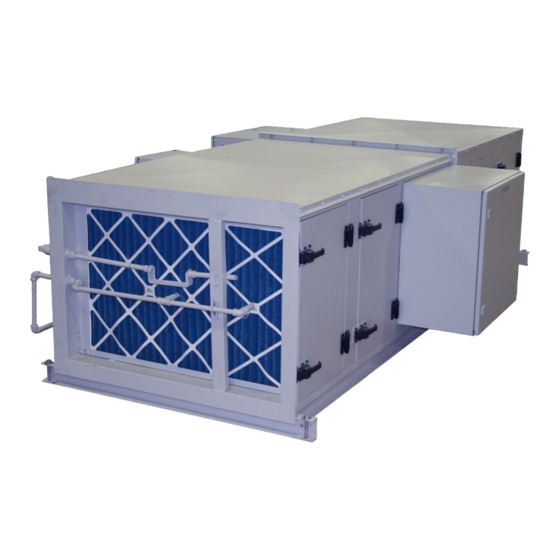
- Page 3 MAJOR COMPONENTS FOR ECOLOAIR 1. EcoloAir Control Panel 3. Exhaust Fan Module 2. Filter Module with Odor Reducing Module 4. Odor Control Cabinet EcoloAir Operation, Maintenance & Service Manual...
- Page 4 FILTER AND ODOR REDUCING MODULES The filter and odor reducing modules are made up of the following: 1. A 2” (51mm) MERV 8 (Minimum Efficiency Reporting Value) 30/30 UL Class 1 disposable pleated Pre-Filter 2. A 15” (381 mm) MERV 14 (Minimum Efficiency Reporting Value) Hi-Flo 95 Class 1 dispos- able Bag Filter.
- Page 5 PRESSURE TRANSDUCER AIR TUBE PARTS Pressure Transducer Air Tube Pressure Transducer Air Tube Connecting Nut Elbow 16 Gauge Top Panel Elbow Lock Nut Mullion 16 Gauge Bottom Panel Structural Base Fire Proof Door Gasket Filter By-Pass Gasket EcoloAir Operation, Maintenance & Service Manual...
- Page 6 ECOLOAIR CONTROL PANEL Features: • Service connection to 120/1/60 Hz. • Microprocessor based. • User friendly touch screen for easy monitoring of parameters in the system. • One control panel per system controls exhaust and MUA fan. • Remote system status monitoring (Internet remote connection as an option). • Setting of the hood airflows (calibration) through touch panel.
- Page 7 How EcoloAir system operates The MC8 controller is used to read the analog signals from pressure transducers and to control speed of exhaust fan motor in order to maintain the constant airflow. It also drives the operation of ecolo compressor according to preset duty cycle or continuous run. A small 7‘‘...
- Page 8 Security screen User Guide screen Moving between screens function is available through the labeled screen buttons at the top of each screen. Press the ‘‘Fast Select’’ button at the lower left corner of the screen to display a pop up menu of screen options.
- Page 9 Touch screen operation The size of the touch screen by default is 7‘‘. Screens explanation : 1. Main screen - Filter screen To Determine Filter Life Remaining: • Turn OFF Ecology Unit, wait 5 minutes. Turn ON Ecology Unit, wait 10 minutes, then check the Filter Life.
- Page 10 2. Ecolo screen --- ecolo odor control screen Ecolo odor control unit operation is enabled through the ecolo screen. The three position selector switch (Off/ Cycle & Continuous) enables the operation of the compressor. Off - unit is not operational. Cycle - unit runs in cycles (on and off).
- Page 11 3. Calibration screen - Calibrate screen How to calibrate the system during start up by using HMI First appearance is the ‘‘filters’’ screen ---appears first when the system is off. By pressing the off/on button, screen displays ‘‘ON’’, the fan starts and goes to the speed which will maintain a default value --- a manual set point of the main DP of 0.5‘‘...
- Page 12 8. When design airflow is reached, press the ‘‘STORE‘‘ button. This will store the calibrated values for main pressure transducer, pre filter, bag filter and final filter transducers. It will also store the calibrated VFD speed (‘‘Store fan speed’’). The HMI displays that calibration is off and the last step is to undo the ‘‘initiate calibration’’...
- Page 13 5. User Guide screen This screen gives a pictorial reference to the main screen. It offers a guide to the features and use of the touch screen and can help navigate the HMI screens. Refer to it when you need help interpreting the information and features of the Main Screen.
-
Page 14: Filter Replacement
FILTER REPLACEMENT Note: Halton filters should be used to avoid the need to re-calibrate. To replace filters, proceed as follows: 1. Shut off fan. 2. Loosen the access door latches and open door. 3. Check how filters are set in place to prevent air by-pass. -
Page 15: Odor Control
HALTON ECOLOAIR FILTER QUANTITY CHART PRE FILTER BAG FILTER FINAL FILTER MERV 8 MERV 14 MERV 16 MODEL CAPACITY FULL SIZE HALF SIZE FULL SIZE HALF SIZE FULL SIZE HALF SIZE 24”x 24”x 2” 24”x12”x2” 24”X24x15” 24”x12”x15” 24”x24”x12” 24”x12”x12” 3000... - Page 16 The Ecolo Unit is set to operate either on a continuous spray or on an intermittent spray cycle while fan is running. A switch is provided on the Ecolo Control Panel to be activated for the desired application. The unit when shipped, will be set for a 20 second spray every 1 minute. This can be adjusted in the field to give the required setting for each particular installation.
-
Page 17: Fan Types
EXHAUST FAN MODULE Access Door Side Panel Fan Pulley Corner Panel Fan Belt Disconnect Switch Motor Hanger or Lifting Brackets Motor Pulley Spring Isolators Electrical Box Terminal Strip Floating Steel Base Pressure Transducer (optional location) Firestat Motor Slide Base Air Tubes for Pressure Transducer (optional location) Structural Base Pressure Transducer Box Cover (optional location) Bottom Panel... -
Page 18: Bearing Replacement
It is unlikely the fan wheel will require replacement. However, if the wheel requires balancing, it can normally be done in the field by a certified fan technician. Should the fan wheel require replacement, the work should only be performed by a Halton certified fan technician. BEARING REPLACEMENT 1. -
Page 19: Sheave Alignment
SHEAVE ALIGNMENT Align the drive by the four-point method with a piece of string or a straight edge. The two sheaves will be aligned when two points (near and far) on the face of each of the sheaves touch the straight edge of the string when the string is a straight line. -
Page 20: Belt Adjustment
BELT ADJUSTMENT Measure the belt span, (see image). Using a spring scale, apply a perpendicular force to any one of the belts at the mid point of the span. Measure the force required to deflect any one of the belts 1/64” (.40mm) for every inch (25mm) of span length. - Page 21 ECOLOGY CONTROL PANEL CONTROL PANEL MODELS EPLV5 - 3: DRY HOODS, w/ECOLO EPLV5 - 3A: DRY HOOD In accordance to UL Standard S647 , each filter component (grease and odor) shall have an interlock to prove the component is in place. Where any of these interlocks are interrupted, the cooking equipment shall not be able to operate, the fans (exhaust and re-circulation) shall be disabled.
-
Page 22: Troubleshooting Guide
TROUBLESHOOTING GUIDE PROBLEM PROBABLE CAUSE SOLUTION Unit not exhausting properly a) Belts slipping or broken. a) Tighten or replace belts. b) Fire damper shut. Check b) Replace fusible link or holding ecology unit and exhaust wire. Check cause. hood. c) Plugged filter. c) Replace filter. -
Page 23: Troubleshoting Guide
TROUBLESHOTING GUIDE PROBLEM PROBABLE CAUSE SOLUTION Filter alarms triggering a) Plugged filter. a) Check filter. Replace if required What setting did it alarm at? Adjust pressure switch if required. b) Broken pressure switch air b) Repair break. Check for cause tube. -
Page 24: Maintenance Instructions
START UP OPERATING INSTRUCTIONS MPORTANT: Initial system start-up and certification by factory authorized personnel only. Operating system prior to certification will void warranty. • Turn on main disconnect switch at EcoloAir fan. • The EcoloAir filter unit is designed to operate with the following pressure drops across each filter stage (measured in inches of water column). -
Page 25: Routine Maintenance
ROUTINE MAINTENANCE 1. A preventive maintenance program is an important aspect of an effective safety program. Consult the manufacturer or other qualified service agents with question concerning changes observed during periodic inspections and routine maintenance. 2. The fan manufacturer’s operating and maintenance recommendations, as well as the components manufacturer’s instructions (such as motor, bearing, drives, etc.) should be strictly followed. -
Page 26: Start-Up Checklist
START UP CHECK LIST 1.1 Before putting any fan into initial operation, the manufacturer’s instructions should be followed. Transportation, handling, and installation can cause fasteners to loosen, and cause misalignment of fan components. Carefully follow this check list when commissioning equipment. 1.2 Lock out the primary and all secondary power sources. - Page 27 6.0 After commissioning and start-up, the fan should be operated and maintained in accordance with the manufacturer’s and component manufacturer’s recommendations. For any questions, please call Halton Service Network at US (270) 237-5600 or Canada (905) 624-301. EcoloAir Operation, Maintenance & Service Manual...
- Page 28 WARRANTY ACTIVATION FORM This form must be completed and returned to Halton in order for your warranty to be valid. Job & Location Information: Job Name: Street Name: Zip Code: City: State: Equipment Start-Up Date: Product Serial Numbers: Contact Information:...
- Page 29 All products sold but not manufactured by Manufacturer will be warranted for a period of twelve (12) months from date of shipment. (Halton’s Warranty Card must be completely filled out and returned to Halton within 3 weeks after the equipment start-up date for your warranty to be valid *IMPORTANT NOTE: “IF”...