Advertisement
Quick Links
Download this manual
See also:
Instruction Manual
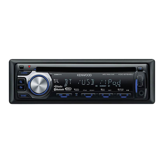
CD RECEIVER
KDC-BT40U/BT645U
KDC-U546BT
SERVICE MANUAL
Panel assy
KDC-BT40U (A64-5015-02)
Bluetooth
Panel assy
KDC-U546BT (A64-5017-02)
Bluetooth
Mounting hardware assy
(J22-0789-03)
* Screw (4x16)
(N84-4016-48)
* Depends on the model. Refer to the parts list.
KDC-BT40U
KDC-U546BT
Escutcheon
(B07-3271-01)
* Screw set
Lever
(N99-1757-15)
(D10-7106-04) x2
* DC cord
(E30-6934-05)
© 2010-1 PRINTED IN JA PAN
B53-0781-00 ( N ) 341
Panel assy
KDC-BT645U (A64-5013-02)
Bluetooth
TDF SPARE-PANEL
MAIN UNIT NAME
KDC-BT40U
KDC-BT645U
KDC-U546BT
* Carrying case
* Remote controller assy (RC-405)
(W01-1710-05)
(A70-2104-05)
* Plastic cabinet assy
(A02-2755-23)
* DC cord
(E30-6933-05)
This product uses Lead Free solder.
This product complies with the
KDC-BT645U
TDF PARTS No.
TDF NAME
Y33-3272-72
TDF-BT40U
Y33-3270-10
TDF-BT06D
Y33-3270-21
TDF-U546BT
RoHS
directive for the European market.
Advertisement

Related Manuals for Kenwood KDC-BT645U


Summary of Contents for Kenwood KDC-BT645U
- Page 1 CD RECEIVER KDC-BT40U/BT645U KDC-U546BT SERVICE MANUAL © 2010-1 PRINTED IN JA PAN B53-0781-00 ( N ) 341 Panel assy Panel assy KDC-BT40U (A64-5015-02) KDC-BT645U (A64-5013-02) KDC-BT40U KDC-BT645U Bluetooth Bluetooth Panel assy KDC-U546BT (A64-5017-02) TDF SPARE-PANEL MAIN UNIT NAME TDF PARTS No.
-
Page 2: Block Diagram
KDC-BT40U/BT645U KDC-U546BT BLOCK DIAGRAM ELECTRIC UNIT (X34- ) R118 ANT. ∗ IC501 PHONE PHONE TUNER LX-BUS Q101 (ATOMIC) POWER ACC DET ACC DET Q103 BU DET BU DET Q701-706 Q707 PRE-OUT Q102 DC-CN FRONT E-VOL MUTE SURGE MUTE PHONE REAR P-STBY REAR/SW ∗... - Page 3 KDC-BT40U/BT645U KDC-U546BT COMPONENTS DESCRIPTION ● SWITCH UNIT (X16-678x-xx) Ref. No. Application / Function Operation / Condition / Compatibility Remote Control Sensor Key Scan Timing Adjust When the base is Hi, key scan starts. Grid Reversing Driver When the base is Hi, GRID1 is ON. Grid Reversing Driver When the base is Hi, GRID2 is ON.
- Page 4 KDC-BT40U/BT645U KDC-U546BT COMPONENTS DESCRIPTION Ref. No. Application / Function Operation / Condition / Compatibility 3.3V→5.0V Level Shift Converts communication signal from 3.3V to 5.0V. 5.0V→3.3V Level Shift Converts communication signal from 5.0V to 3.3V. Power supply for digital back-up. BU1.5V / BU3.3V Regulator Power supply for mechanism μ-COM.
- Page 5 KDC-BT40U/BT645U KDC-U546BT MICROCOMPUTER’S TERMINAL DESCRIPTION ● SYSTEM μ-COM : IC1 on X34- (ELECTRIC UNIT) Truth Value Pin No. Pin Name Application Processing / Operation / Description Table Not used Output L fi xed REMO Remote control input Detects pulse width Not used Output L fi...
- Page 6 KDC-BT40U/BT645U KDC-U546BT MICROCOMPUTER’S TERMINAL DESCRIPTION Truth Value Pin No. Pin Name Application Processing / Operation / Description Table S SOC CLK Serial clock input from Bolero Not used Output L fi xed Communication request from mecha- S SOC REQ nism to system μ-com CD LOS SW CD loading detection CD DISC12 SW...
- Page 7 KDC-BT40U/BT645U KDC-U546BT MICROCOMPUTER’S TERMINAL DESCRIPTION Truth Value Pin No. Pin Name Application Processing / Operation / Description Table STANDBY source or momentary power-down: L, PWIC MUTE Power IC mute TEL mute: L Not used Output L fi xed PWIC STBY Power IC standby control POWER ON: H, POWER OFF: L MUTE...
- Page 8 KDC-BT40U/BT645U KDC-U546BT TEST MODE ■ Example Description of display Description ÷ ÷ ÷ ÷ ÷ ÷ ÷ A symbol “■” in the key column indicates that the key should be pressed and held. Description of display Description Disc Eject times display (Max. 65535 times). Disc Eject times While Disc Eject times is displayed, press and hold for 2 display...
- Page 9 KDC-BT40U/BT645U KDC-U546BT TEST MODE Description Default values BASS BOOST SystemQ / dB EQ NATURAL (FLAT) BEEP Beeps when the key is pressed briefl y. PREOUT REAR ■ Test mode specifi cation in STANDBY source Description of display Description Common All lights ON. All lights ON.
- Page 10 · To clear the preset telephone numbers (in the data fl ash ROM) · To write “KENWOOD BT CD/R-3P2” in the friendly name (in the fl ash memory of the BT module) · To write “0000” in the PIN code (in the fl ash memory of the BT module)
- Page 11 KDC-BT40U/BT645U KDC-U546BT TEST MODE • CD information display mode (sub-mode) Description of display Description Mechanism error log 1 (Latest) XX: Error number. The “--” is displayed in case there is no error. Mechanism error log 2 (Latest) CD mechanism error XX: Error number.
- Page 12 KDC-BT40U/BT645U KDC-U546BT TEST MODE • Design version information display mode (sub-mode) Description of display Description Destination terminal TYPE indicates μ-com destination, and indicates condition condition display of the destination terminal in real-time. Development ID BAND Development code - Version (system μ-com) –...
- Page 13 KDC-BT40U/BT645U KDC-U546BT TEST MODE • TUNER setting adjustment mode This mode is to adjust TUNER setting. Note Press this key to change the mode to the TUNER setting adjustment (Press and hold the key for 1 second). When the source is FM, frequency is switched to 98.3MHz at the start of the adjustment mode. ■VOICE Press and hold the [VOICE] key.
- Page 14 KDC-BT40U/BT645U KDC-U546BT TEST MODE Description of display Description This is to clear the FST adjustment mode (in normal operation) (The display returns to the normal display – 7 . 9 and the test mode is retained.) Frequency is switched to 97.9MHz. RETURN Mode clear This is to clear the FST adjustment mode (when failed...
- Page 15 KDC-BT40U/BT645U KDC-U546BT TEST MODE ■ Test mode in CD source Display mode default P-Time • Procedure in CD-DA media (KTD-02A) Description of display Operation Every time pressed, jumps to the track shown below. No.9 → No.15 → No.10 → No.22 → No.12 → No.13 → Track up procedure No.14 →...
- Page 16 Press and hold this key for 2 seconds when a capacitor leak is ■2 detected to clear the number of detection. (Clear the Data Flash ROM) ■ FM/AM Channel space switching (KDC-BT645U/U546BT only) Procedure Note While Power OFF, pressing and holding [1] key and [5] key, and press FM200kHz/AM10kHz ↔...
- Page 17 KDC-BT40U/BT645U KDC-U546BT PC BOARD PC BOARD (COMPONENT SIDE VIEW) (FOIL SIDE VIEW) SWITCH UNIT SWITCH UNIT X16-678x-xx (J76-0650-02) X16-678x-xx (J76-0650-02) TP37 X16-678x-xx X16-678x-xx Ref. No. Address Ref. No. Address C100 R105 Refer to the schematic diagram for the values of resistors and capaci- tors.
- Page 18 KDC-BT40U/BT645U KDC-U546BT PC BOARD (COMPONENT SIDE VIEW) ELECTRIC UNIT X34-662x-xx (J76-0648-02) 11 12 8 4 3 9 10 6 R813 C806 R810 C875 C876 R811 R808 R710 R704 C807 R703 R709 R716 R715 R802 Q702 R803 R118 D106 D605 D109 D604 D108 R112...
- Page 19 KDC-BT40U/BT645U KDC-U546BT X34-662x-xx Ref. No. Address W103 R101 W104 IC51 R102 IC52 Q101 D107 R110 Q103 R152 Q104 R151 Q701 W101 Q702 Q703 Q704 Q705 Q706 Q901 Q902 W105 W102 R916 R915 R918 C912 R279 R278 A900 Refer to the schematic diagram for the values of resistors and capacitors.
- Page 20 KDC-BT40U/BT645U KDC-U546BT PC BOARD (FOIL SIDE VIEW) ELECTRIC UNIT X34-662x-xx (J76-0648-02) R812 TP316 TP10 TP315 C857 C855 AC-GND C853 TP18 TP17 R111 R114 R117 R115 R116 A-DC-ERR C406 L750/R406 C405 C407 TP54 L751/R405 SEL1 SEL2 TP52 C914 C915 C923 R281 R282 R340 O G I...
- Page 21 KDC-BT40U/BT645U KDC-U546BT X34-662x-xx Ref. No. Address IC501 R604 IC900 IC901 R713 Q102 Q105 Q301 Q707 R513 C530 C525 1/R405 C532 R525/C533 R618 R620 C501 C507 C506 R340 C510 IC501 C509 C518 C512 C516 C517 C515 CNVSS R205 C514 C513 R619 C204 R208 R207...
- Page 22 KDC-BT40U/BT645U KDC-U546BT PC BOARD (COMPONENT SIDE VIEW) X32 B/2 12EJE ORG LOS GRE GND BLU R105 CD PLAYER UNIT R102 X32-6260-01 A/2 (J76-0572-02) AGND CD RST IOP+ BUCK A3.3V R119 R177 CP11 R101 R121 12EJE SW R171 R118 LOS SW R117 SRAMSTB BU5V...
- Page 23 KDC-BT40U/BT645U KDC-U546BT PC BOARD (FOIL SIDE VIEW) X32 B/2 CD PLAYER UNIT X32-6260-01 A/2 (J76-0572-02) R127 R120 R128 CP15 R166 CP12 C102 R167 R68 R69 R132 R131 X32-6260-01 Ref. No. Address Refer to the schematic diagram for the values of resistors and capacitors.
- Page 24 KDC-BT40U/BT645U KDC-U546BT REAR FRONT REAR/SUB PRE-OUT ELECTRIC UNIT TP91 (X34-662x-xx) ∗ W608 ∗ ∗ C875 C876 680P 680P ∗ ∗ R703 R704 R709 R710 R715 R716 MUTE DRIVER Q701 Q702 Q703 Q704 Q705 Q706 PRE-OUT Q707 BU5V REAR FRONT REAR /SUB ANT.
- Page 25 KDC-BT40U/BT645U KDC-U546BT ∗ LX BUS BU5V C201 5.0V VOUT R604 RESET IC TP432 D605 TP158 D604 R334 D601 TP180 3.3V REMO D650 BYTE TP412 R203 R201 CNVSS C203 XCIN 32.768kHz C202 R204 XCOUT 100K RESET XOUT ∗ 16.000MHz SYSTEM u-COM 5.0V VCC1 ∗...
- Page 26 KDC-BT40U/BT645U KDC-U546BT DC IN P ANT SW5V ∗ D103 FL,FR R102 4.7K Q105 MUTE ∗ R152 Q104 MUTE CONT MUTE CONT R803 POWER IC SW 14 TP17 C105 R111 R110 0.01 Q11,12 C807 AUD SDA 3.3V CONTROL SW for SERVO+B ACC DET OFFDET R113...
- Page 27 KDC-BT40U/BT645U KDC-U546BT DC IN F1 10A (F52-0023-05) D101 R101 4.7K TP10 3300u16 ∗ R152 ∗ C859 DTC114YUA 0.01 TP17 R106 R110 3.3K 2SC4081 R108 Q102 URGE Q101 R115 C101 0.01 Q103 R116 R109 6.8K BU DET DTC144EUA 4.4V KTA1046-P 0.47 DAP202U DA204U TP52...
- Page 28 TP82 SWITCH UNIT (X16-678x-xx) : PIC95603 D9,10 : RK4.7KG(B2) R52, DESTI- UNIT B30-1566-05 D56-62,84-86 MODEL NAME NATION 54-57 : RT1N441U-T111 D52-62,84-86 KDC-BT645U B30-1781-05 B30-1781-05 Q21-23 : RT1P237M-T111 ∗ 0-10 1.5K (BLUE) (BLUE) KDC-U546BT ∗ B30-1779-05 B30-1566-05 3-BT-266INK D79,82 : DA204U...
- Page 29 KDC-BT40U/BT645U KDC-U546BT col5 col3 col1 col3 col1 col3 col1 col6 col4 col2 col4 col2 col4 col2 (3G) (2G) (1G) 10.3V (1G-3G) CP11 AUDIO ETURN BAND EJECT Y MATRIX BAND DISP EJECT CAUTION : For continued safety, re place safe ty critical com- po nents only with manufacturer’s rec om mend ed parts (refer to PANEL parts list).
- Page 30 KDC-BT40U/BT645U KDC-U546BT CD PLAYER UNIT (X32-6260-01) (A/2) MECHA. (X92- ) SLED OUT /LOAD 4ch BTL DRIVER TP123 TP128 1.7V ZDET 7.5V POWVCC1 R132 100 TP124 LOADING & POWGND1 SLED IN SLED TP127 /EJECT SLIN MOTOR VO1- R131 200K LDIN SPDL+ VO1+ TP122 BIASSW...
- Page 31 KDC-BT40U/BT645U KDC-U546BT ZDET ZDET D1.5V DRVMUTE B3.3V-2 B3.3V TP95 B3.3V CD REQ TP93 TP94 OUTPUT ZDET TP68 B3.3V B3.3V 3.3V ZDET CONTROL SIGNAL INVERTER AGND DVSS3R 1.7V TP92 R112 4.7 R28 1K 3.3V DVDD3R DSP RST 3.3V R113 4.7 R27 100 DVDD3L 1.7V TP80...
- Page 32 KDC-BT40U/BT645U KDC-U546BT TP31 FCS- TP32 TRK- A3.3V TP33 TRK+ TP34 FCS+ TP59 RFRP TP37 1.5V DPU1 TP38 TP60 (X92- ) TP40 PD R104 OPTICAL 2.2M TP41 C+D R103 PICKUP 2.3V TP42 F 0.2V TP43 A AVSS3 TP44 B 1.7V 2.0V TP45 E FP11 1.9V...
- Page 33 KDC-BT40U/BT645U KDC-U546BT EXPLODED VIEW (CD MECHANISM) : N09-6108-15 : N09-6426-15 : N09-6735-05 : N09-6737-15 : N09-6738-15 : N19-2335-14 : N35-2003-48 : N39-1720-48 (X32) DPU1 (X32) Parts with the exploded numbers larger than 700 are not supplied.
- Page 34 KDC-BT40U/BT645U KDC-U546BT EXPLODED VIEW (UNIT) DME1 A : N09-6758-05 : N35-2610-48 : N80-2006-48 : N80-2008-43 : N86-2604-43 : N86-2606-48 : N80-3008-48 (X34-) : N83-3005-48 W551 : N83-3016-48 : N86-2606-48 : N89-3010-48 (X34) (X34-) (X34) IC51 (X16-) 268 (X34- : ELECTRIC UNIT) On bottom of IC51 there is a soldering part.
- Page 35 D9 ,10 ✽ RKZ4.7KG(B2) ZENER DIODE DA204U DIODE N84-4016-48 PAN HEAD TAPTITE SCREW HZM6.8ZMWA-E ZENER DIODE N99-1757-15 SCREW SET DA204U DIODE N09-6758-05 TAPTITE SCREW 3-BT-266INK FLUORESCENT INDICATOR TUBE K: KDC-BT645U M1: KDC-U546BT E2: KDC-BT40U Indicates safety critical com po nents.
- Page 36 R95 -98 RK73GB2A223J CHIP R J 1/10W CC73GCH1H560J CHIP C 56PF C101,102 CK73GB1H103K CHIP C 0.010UF K R101 RK73GB2A221J CHIP R J 1/10W R102 RK73GB2A4R7J CHIP R J 1/10W K: KDC-BT645U M1: KDC-U546BT E2: KDC-BT40U Indicates safety critical com po nents.
- Page 37 35WV CK73GB1H152K CHIP C 1500PF C703-706 CD04AV1V100M ELECTRO 10UF 35WV CC73GCH1H471J CHIP C 470PF C703,704 CD04AV1V100M ELECTRO 10UF 35WV CK73FB0J106K CHIP C 10UF C801-804 CK73GB1A224K CHIP C 0.22UF K: KDC-BT645U M1: KDC-U546BT E2: KDC-BT40U Indicates safety critical com po nents.
- Page 38 BINDING HEAD TAPTITE SCREW R325 RK73GB2A000J CHIP R J 1/10W R327,328 RK73GB2A473J CHIP R J 1/10W CP201 RK74HB1J101J CHIP-COM 100 J 1/16W R330 RK73GB2A101J CHIP R J 1/10W K: KDC-BT645U M1: KDC-U546BT E2: KDC-BT40U Indicates safety critical com po nents.
- Page 39 CHIP R J 1/8W RT1N241M-T111 TRANSISTOR R802 RK73GB2A333J CHIP R J 1/10W RT1P241M-T111 TRANSISTOR R803 RK73GB2A473J CHIP R J 1/10W R804 RK73GB2A331J CHIP R J 1/10W RT1N441M-T111 TRANSISTOR K: KDC-BT645U M1: KDC-U546BT E2: KDC-BT40U Indicates safety critical com po nents.
- Page 40 TORSION COIL SPRING G01-4683-24 EXTENSION SPRING G01-4684-04 EXTENSION SPRING G01-4685-04 EXTENSION SPRING G01-4686-14 EXTENSION SPRING G01-4688-14 EXTENSION SPRING G01-4692-24 TORSION COIL SPRING G02-1587-04 FLAT SPRING G02-1588-04 FLAT SPRING G13-1297-04 CUSHION K: KDC-BT645U M1: KDC-U546BT E2: KDC-BT40U Indicates safety critical com po nents.
-
Page 41: Specifications
Installation size (W x H x D) ......182 x 53 x 155mm Frequency range (9kHz space) ....531kHz~1611kHz Weight ................1.3kg Usable sensitivity (S/N=20dB) ........36μV LW tuner section KDC-BT645U Frequency range ......... 153kHz~279kHz Usable sensitivity (S/N=20dB) ........57μV FM tuner section Frequency range (200kHz space) ..87.9MHz~107.9MHz CD player section Usable sensitivity (S/N=26dB) ....11.2dBf (1.0μV/75Ω) - Page 42 Weight ................1.3kg CD player section Laser diode ..............GaAlAs Digital fi lter (D/A) ....... 8 Times Over Sampling KENWOOD follows a policy of continuous advancements D/A converter ..............24Bit in development. For this reason specifi cations may be Spindle speed ..........500~200rpm (CLV) changed without notice.